|
|
|
|
|
|
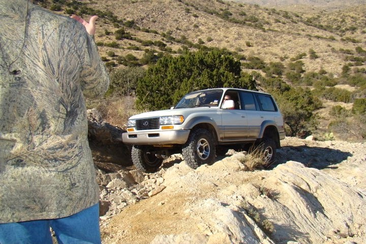
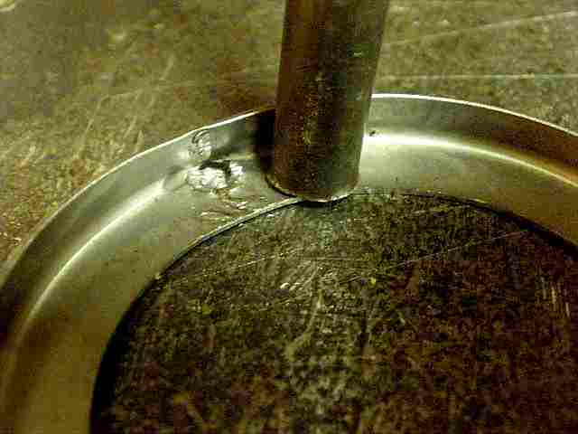
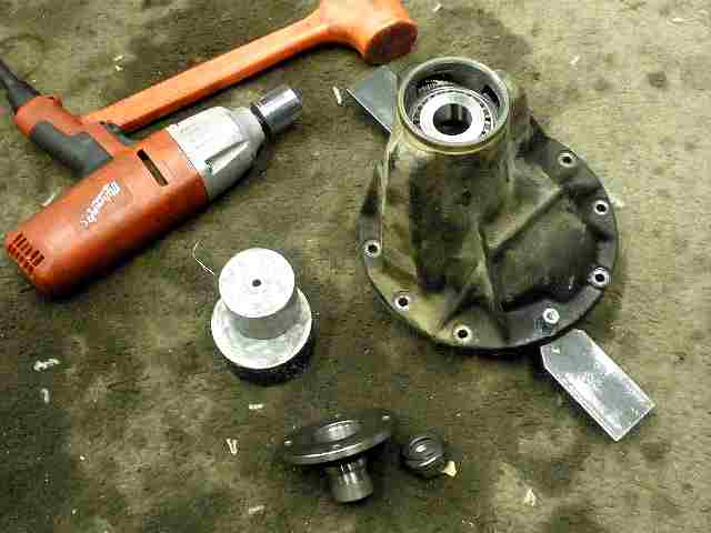
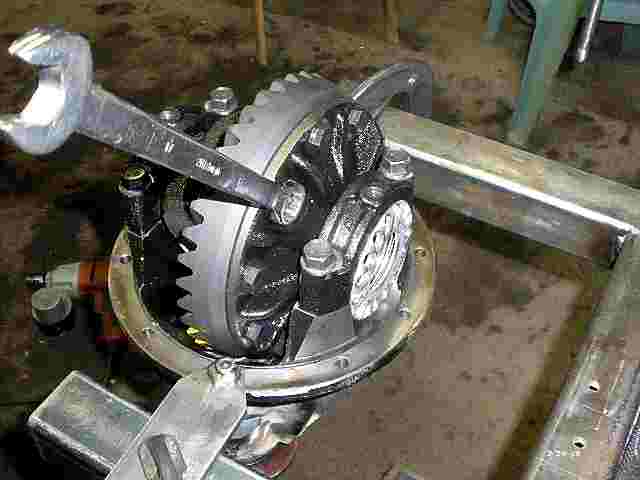
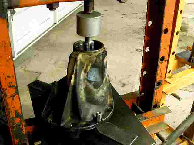
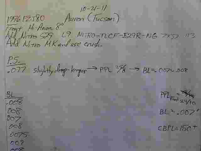
Aaron is in Tucson and likes to play on the trails in Reddington Pass nearby. Here he is going up the dangerous hill just past the turnoff to Chiva Falls. The 410's and 35" tires were putting a strain on the auto. Time to pull the 3rds and deliver them to me...100 miles away. |
|
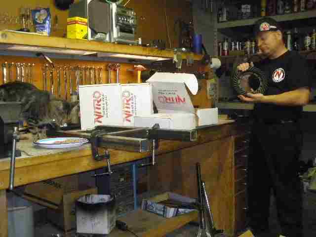
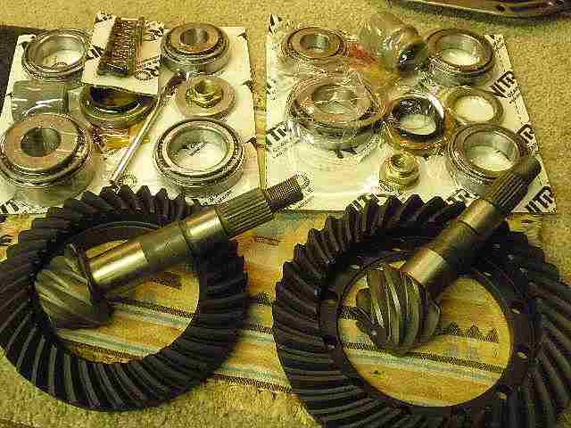
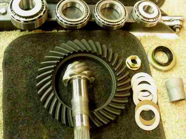
He also brought Nitro gears with him. Excuse the picture quality. I over-compressed the jpegs on this go-around. |
|
...and Nitro master install kits. Crush sleeves would suffice just fine for his usage. |
|
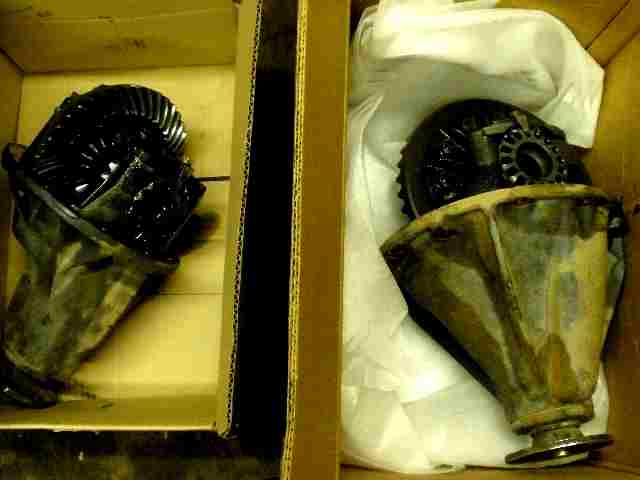
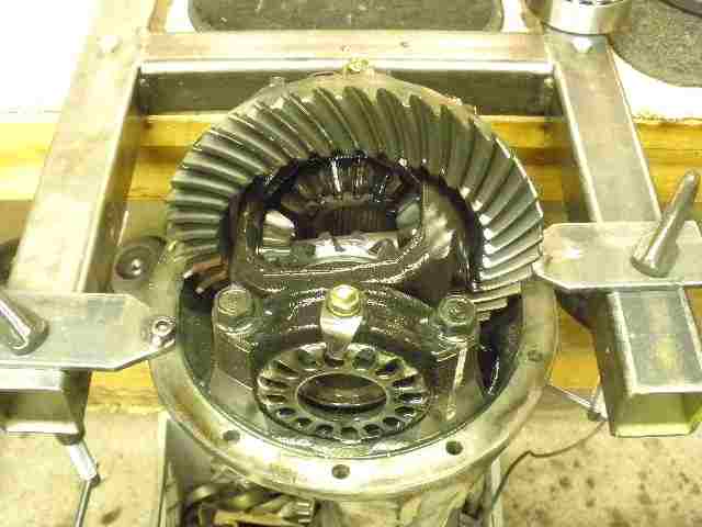
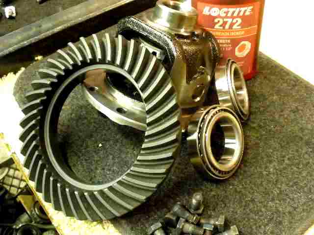
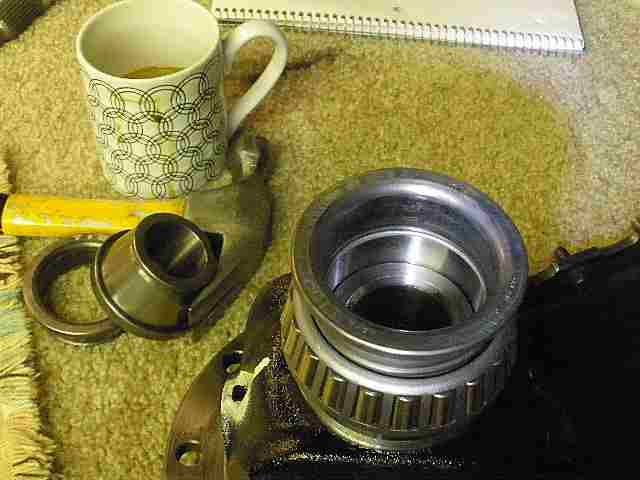
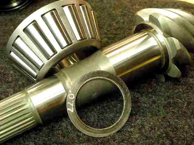
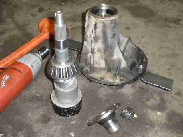
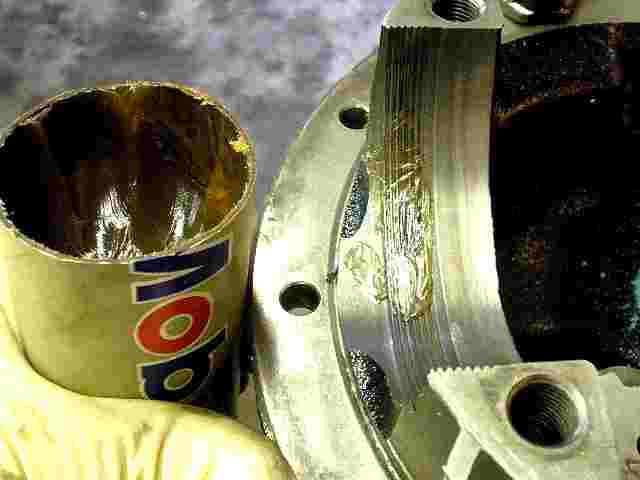
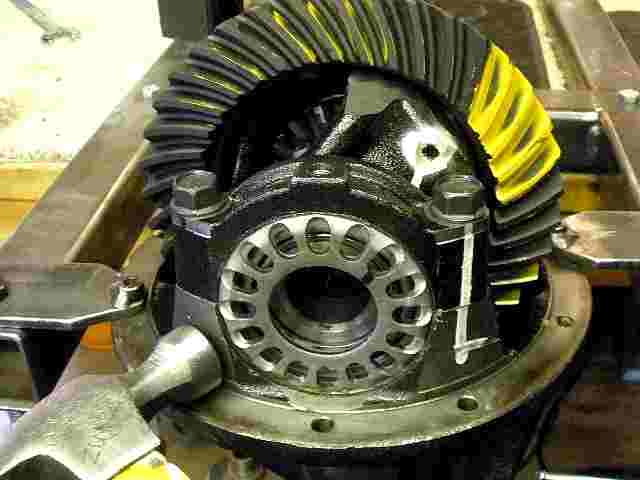
The front hi-pinion 8" is on the left and the monster 9.5" rear is on the right. This link will cover the install of the front 8". |
|
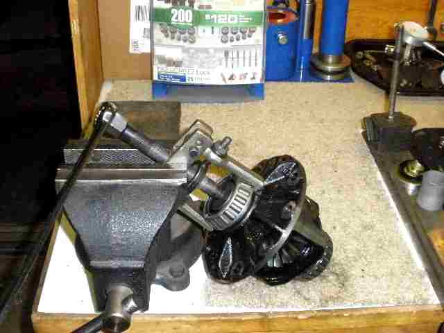
The 8" is secured to the simple bench fixture. |
|
The gears and master kit are set out and organized. Everything is here. |
|
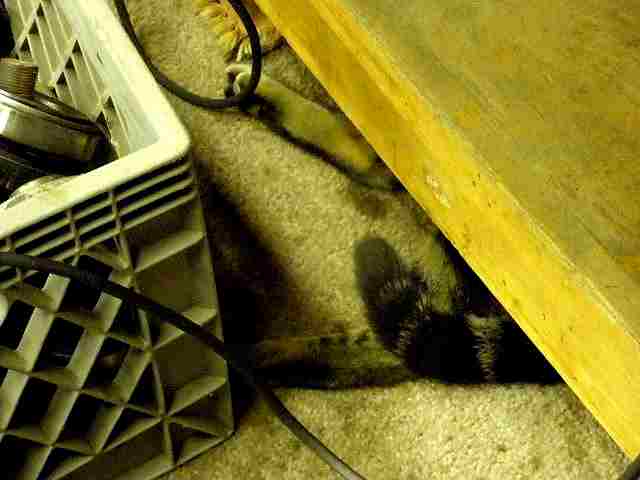
Bullseye is trying to sleep under the bench...wait until he hears that noisy electric impact :) |
|
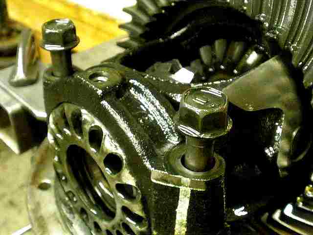
The 4 cap bolts are removed and the 2 pinion open case can then be removed. |
|
The 10 ring gear bolts are now loosened up... |
|
The lock-tabs will be thrown out. I prefer to use lock-tite. These hardened steel tabs are not re-useable anyways. They don't like to be re-bent and break off sometimes. |
|
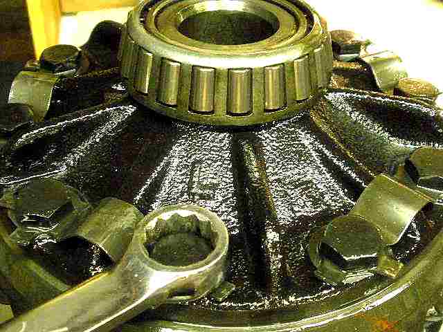
Both carrier bearings can now be pulled off with the proper tool. |
|
First, to install the new bearings... |
|
I often use an old bearing race to tap the new bearing on part way at least. |
|
Save your old bearings as they come in quite handy. |
|
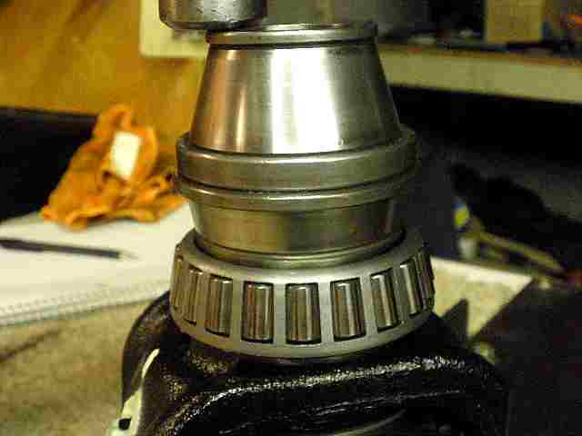
Both bearings can now be pressed on all the way with the 12 ton press...using about 1 ton of actual force I figure. |
|
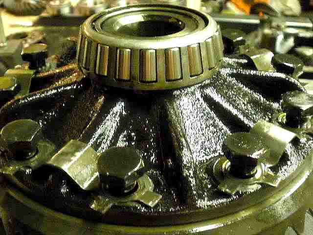
The Nitro ring did not require a press to install. With a little bit of jiggling, it went on very nicely. I could not detect any play but I could spin it on the case mounting surface as shown in the pic. Basically, it was a perfect fit and made the threading of the 10 ring bolts a snap. |
|
As usual, red Loctite is applied... |
|
...and 75 ft/lbs is applied to all 10. |
|
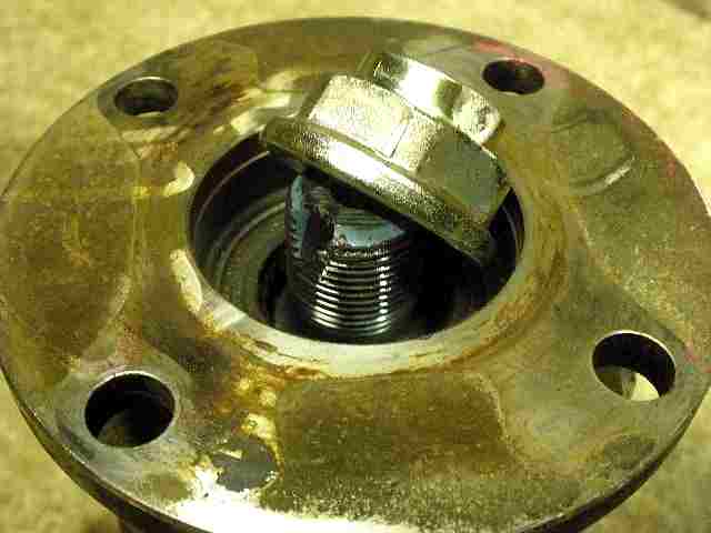
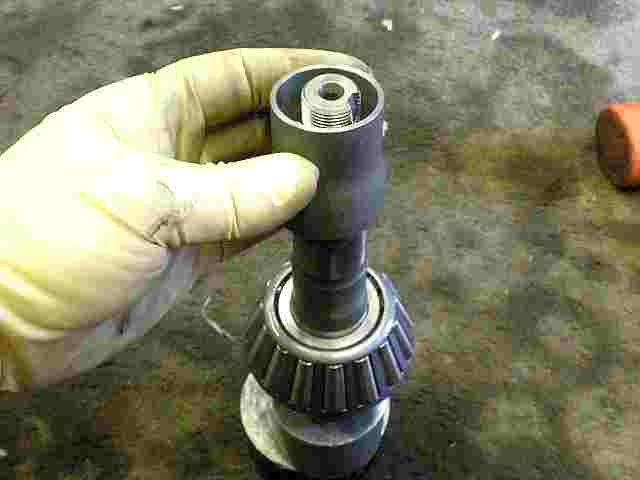
Now, time to tear down the pinion end of things. The electric impact made quick work of the 30mm nut....2 seconds and this is the result. |
|
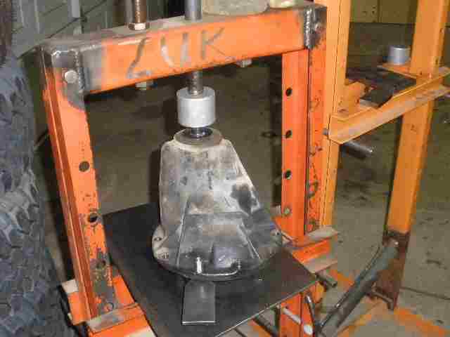
Press the pinion out. |
|
The seal is removed with the prying lever action of a chisel and hammer. |
|
Every 8" hi-pinion is supposed to have a bladed oil slinger. |
|
I have had very good luck with removing the outer race and oil retainer with the long slender drift pin punch shown above. |
|
Done right, only 1 hole will be punched through the retainer to impact the race and loosen it. |
|
Then I can use a larger round flat punch to re-close the hole up. |
|
Then place the retainer in such that the damaged area is close to the straight up or "12 o'clock" position. Tap it in place fully. |
|
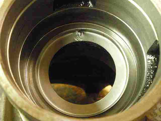
Now the outer pinion race can be tapped in place... |
|
...using an old race up against the new race. I don't use the soft chisel directly up against the new race edge like I used to....I saw some oscillating torque readings doing it that way and no more of that. |
|
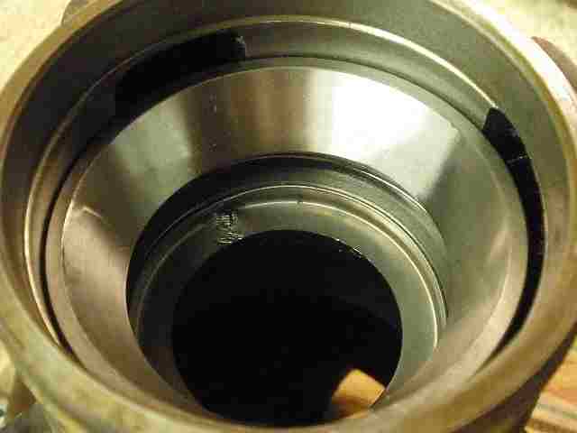
The larger inner race is a little trickier to get started evenly but once it is the press will push it in easy. Again, I am using an old race up against the new one to prevent any race edge deformation. |
|
Bearings in....now to get the pinion ready. |
|
Probably best to re-use the orignal .077" pinion shim so we will. |
|
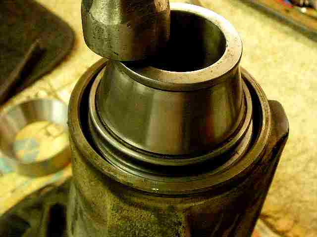
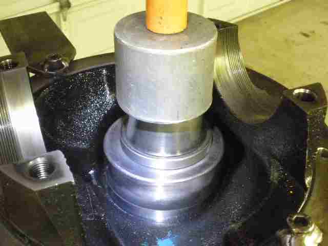
I have a favorite piece of pipe that fits perfect over pinion shaft and contacts the bearing properly. This bearing did take some good push to get it in place...nothing the 12 ton couldn't handle though. |
|
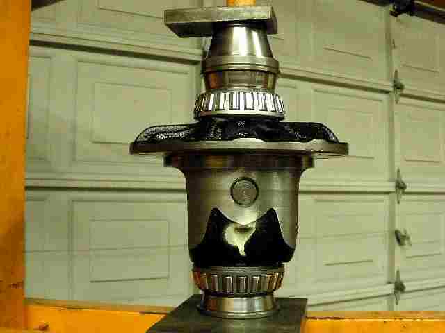
Only have this one pic of the loading of the pinion end but it is straight forward....as shown in the above pic, place the pinion assembly on the aluminum spacer blocks...pick up the heavy main carrier and situate it on the pinion...place flange on pinion end.... tap it down with the lead filled hammer far enough to get the nut on...tighten nut with electric impact until about 10 in/lb of PPL is reached. It is quite possible to over-tighten the nut resulting in dents in the races so use caution. Gear oil should be liberally applied to both upper and lower pinion bearings to make the PPL readings mean something. Done. |
|
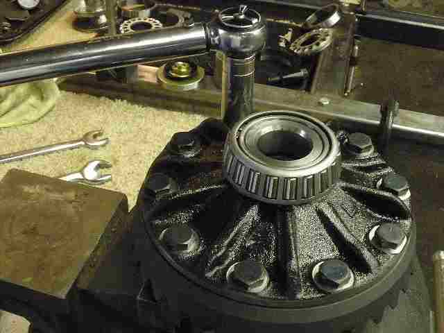
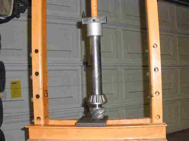
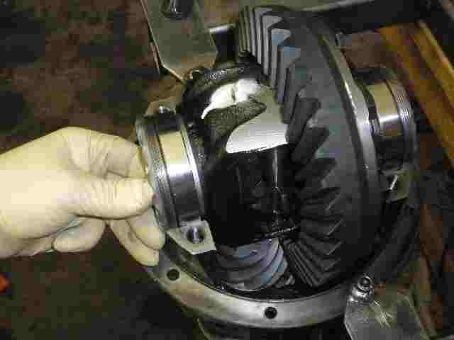
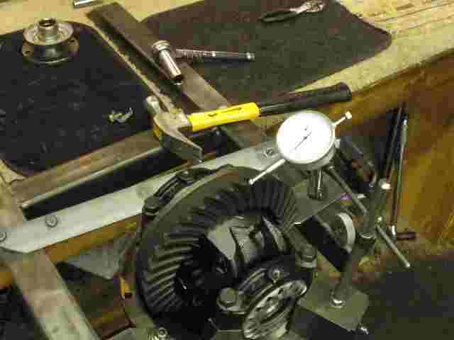
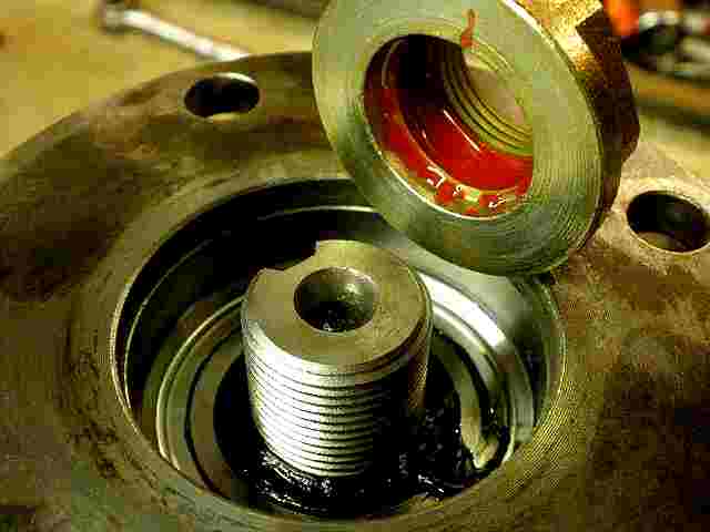
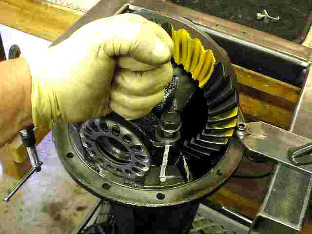
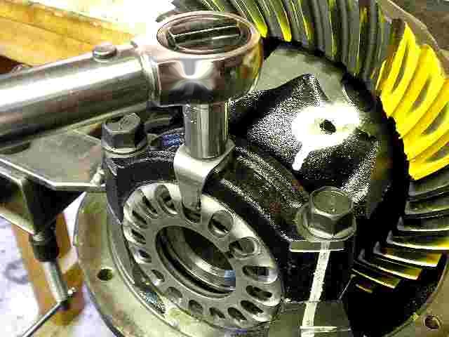
As shown in the pic, it sure is nice to have a solid fixture where the work can be performed in this vertical plane. The case is dropped in the carrier and races are in place. The adjuster wheels are loaded in place and I make sure they are engaging the threads correctly. |
|
The bearing cap is hovered over it and the 2 long bolts are threaded in just about 3 turns each. If it is done right, then the bearing cap can be jiggled down and one light palm tap will seat it down fully 100% and this means the threads are in proper mesh. In the past, I have received a number of 3rds where the threads were partially mangled due to somebody not getting the wheel in the right thread groove....if the threads are damaged enough then the whole 3rd might be garbage. |
|
Light taps while the bolt is snugged up will help get the upper and lower threads into alignment. After all 4 bolts are snugged up, I use the socket wrench to tighten them close to the 70 ft/lb spec....no torque wrench needed at this stage of the install....they just need to be tight and that's all. |
|
Some carrier bearing pre-load is introduced and BL is guided near .008". |
|
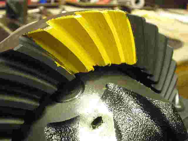
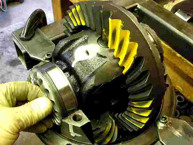
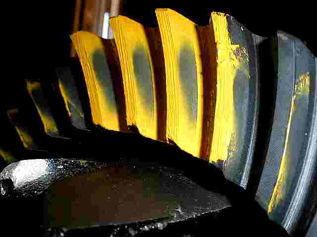
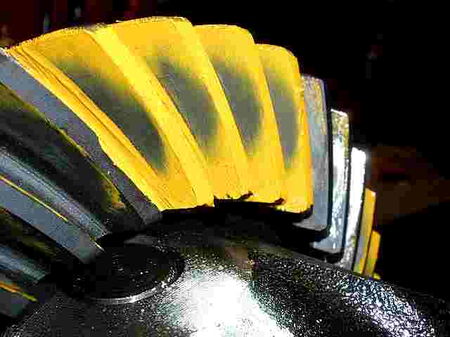
Yellow marking compound is applied typically to 3 teeth both sides. |
|
The ring gear is turned to get the paint into position. |
|
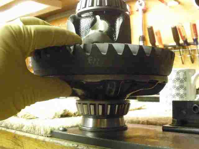
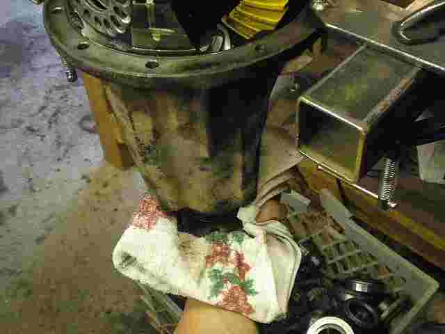
I get excellent paint impressions with this simple method....grab the flange using a bulky rag like this....apply some resistance... |
|
Place a 17mm wrench on the ring gear bolt head and rotate the ring back and forth maybe 3 times. Done. |
|
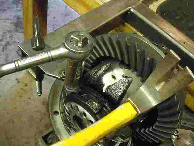
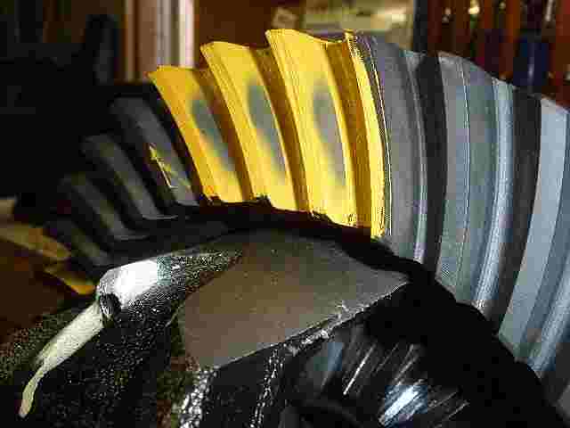
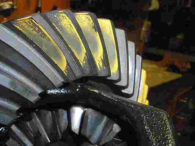
Nice. This is the drive side and looks to be slightly deep which I prefer especially in this Hi-pinion front application. |
|
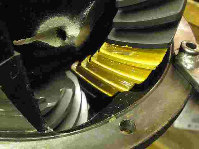
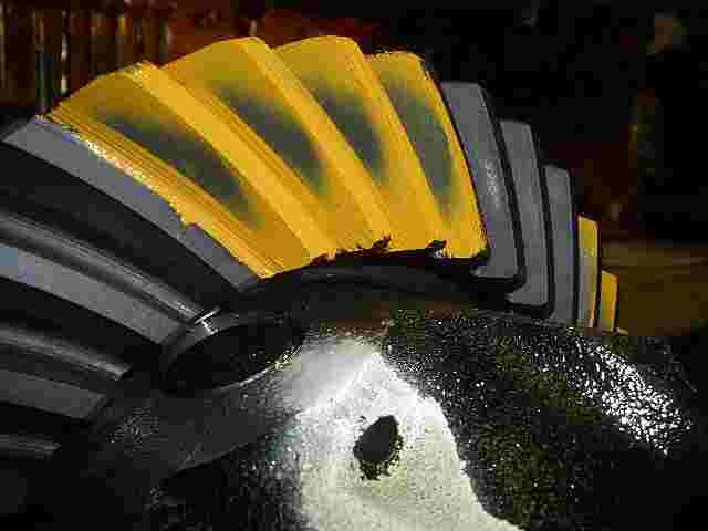
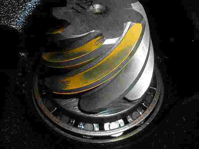
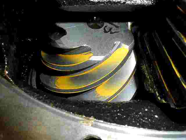
Coast looks deep also. |
|
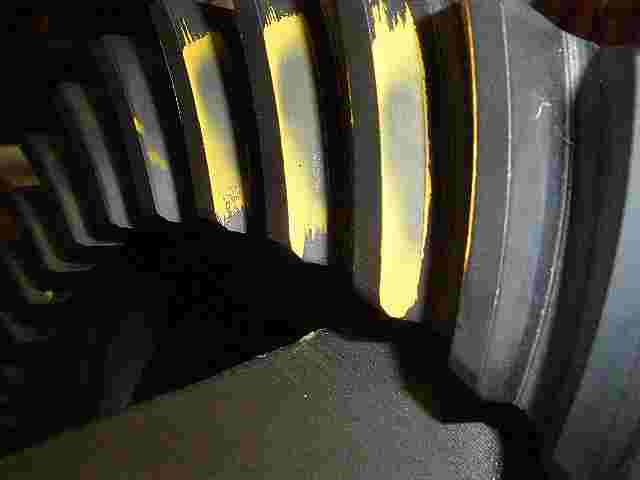
Another shot of a reverse painted tooth....drive |
|
coast.... |
|
3 teeth on the pinion have been reverse painted so here they are... |
|
tooth 2 |
|
tooth 3 |
|
I'm very satisfied with the patterns so now to break it down and install the crush sleeve. |
|
Crush is placed on the pinion... |
|
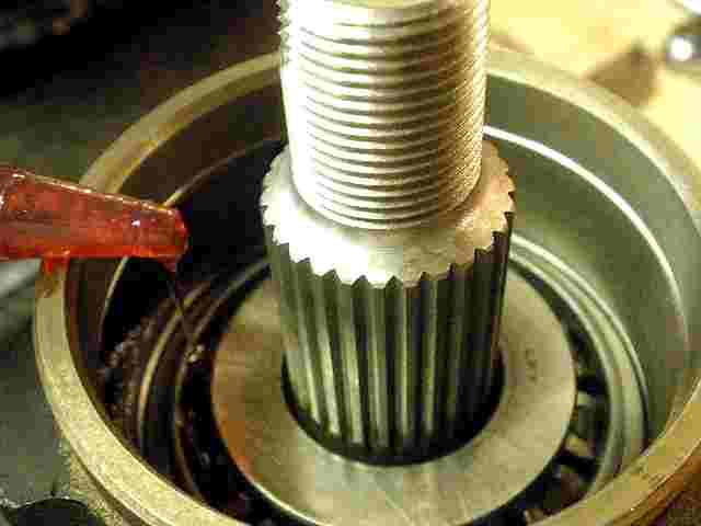
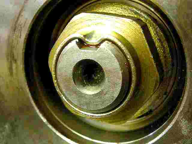
To get the upper pinion bearing fully seated in place involves placing the pinion head on the aluminum spacer blocks like it was shown earlier and use the pinion flange to seat the bearing down with some coaxing from the lead filled hammer. Then, as shown above, a good amount of gear oil is applied to both the upper and lower pinion bearings. |
|
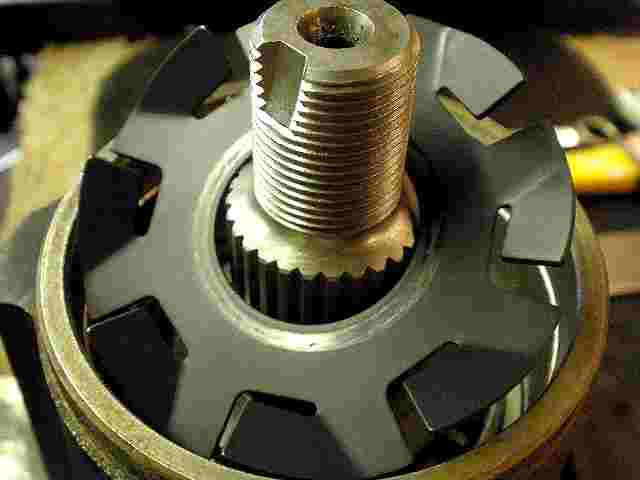
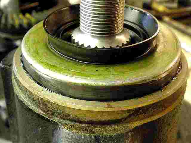
Kinda looks like a boat prop. Anyways, the oil slinger is dropped in place. |
|
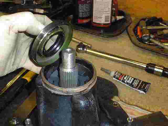
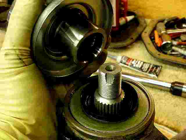
Now the pinion seal put in place. I have a thick bead of grease surrounding the coiled spring. I have rtv on the outside of the seal also. |
|
In the past, I have used a hammer to carefully tap it down but it is risky .... |
|
...and, it's just better to make your own seal driver from old sacrificial flanges and races...and a mig welder. |
|
Aaron's flange has been cleaned up and lightly oiled. |
|
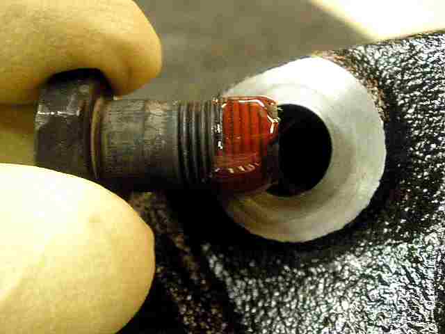
Red Loctite on the new 30mm pinion nut. |
|
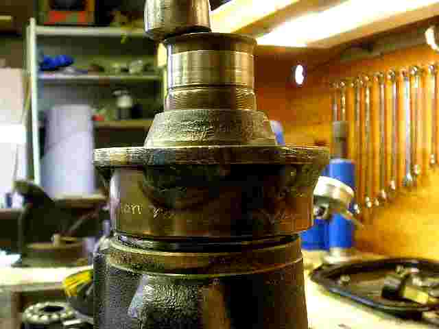
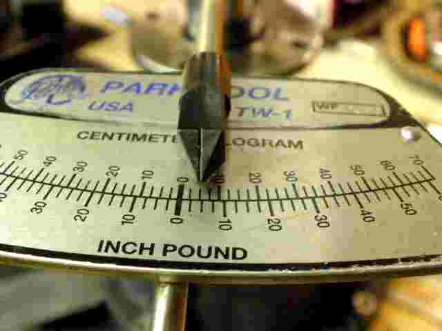
Even with the nut loose, I still can measure about 4 in/lb of SEAL DRAG. This has to be realized when setting the final PPL. |
|
So, using my 3 foot cheater bar, I slowly crush the collar a little at a time until I reach my target PPL of 14. Take off the 4 for seal drag and that leaves 10 real in/lb of PPL. Ding the nut and this end is done. |
|
In the past, I used aluminum anti-seize on these threads but I also like to use a good thick grease every now and then. |
|
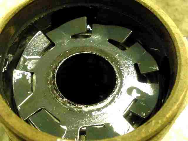
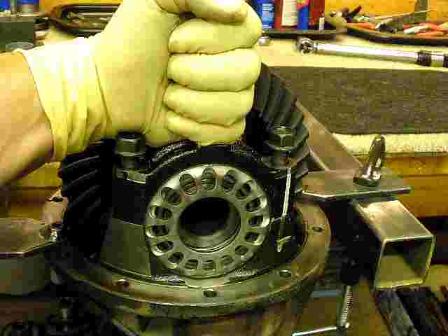
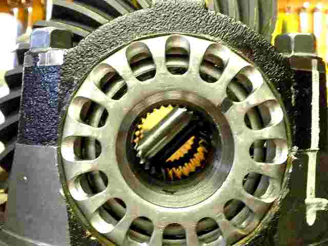
wheel mesh is checked....threads are in alignment. |
|
The bearing cap is fisted down |
|
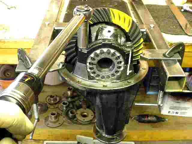
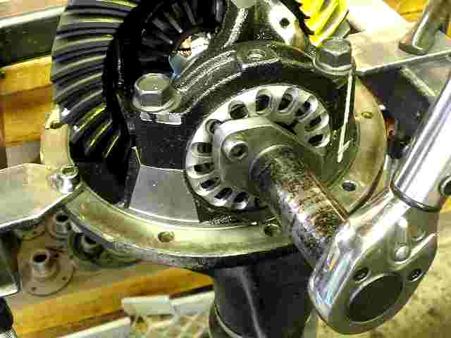
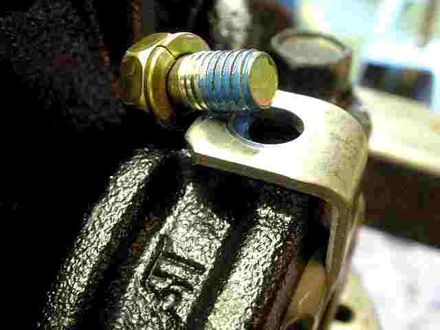
75 ft/lb works very well for a final torque value. |
|
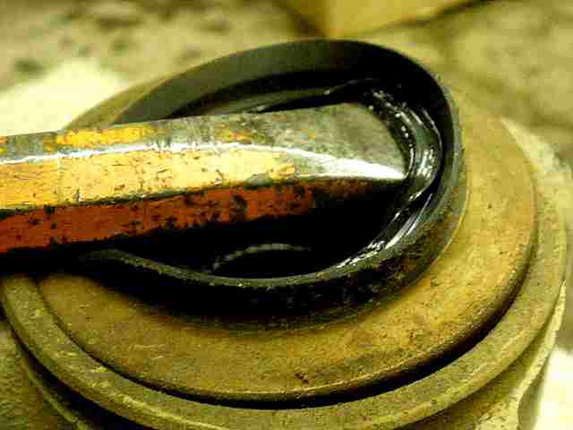
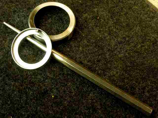
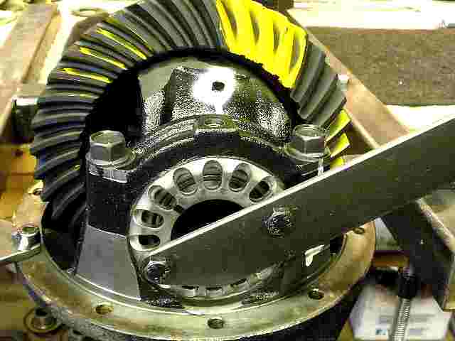
Final tightening of the wheels with my homemade tool. |
|
While turning the pinion back and forth, I send shock waves safely through the sides shown here. I do this on the other side also. This equalizes the carrier bearing tensions and prevents changes in the backlash after it goes down the road. |
|
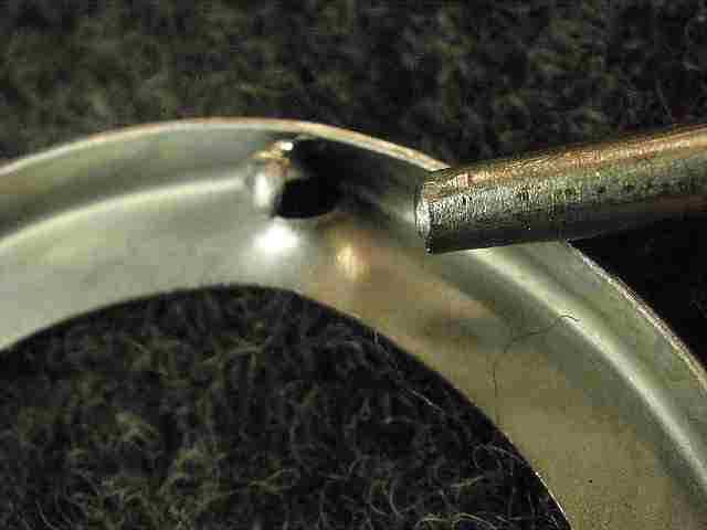
Another homemade tool, I verify the CBPL is about 150 ft/lb in this case. 150 on the wheels equates to about 15 inch/pounds of actual carrier bearing drag. I have tested and verified this 5 years ago. |
|
a wasted picture.... |
|
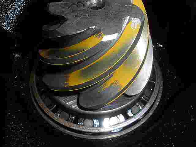
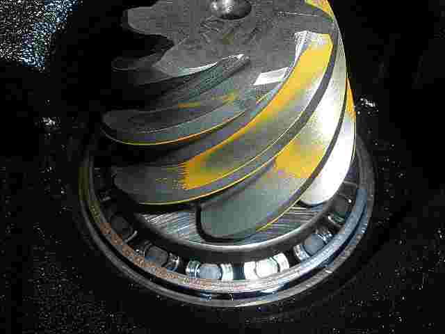
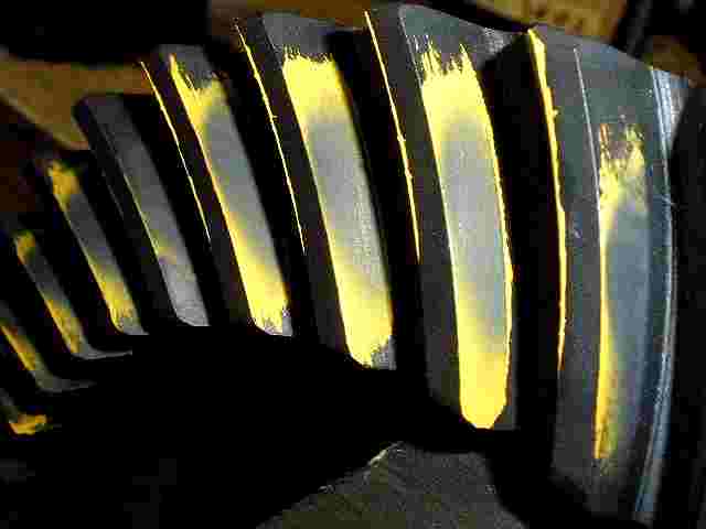
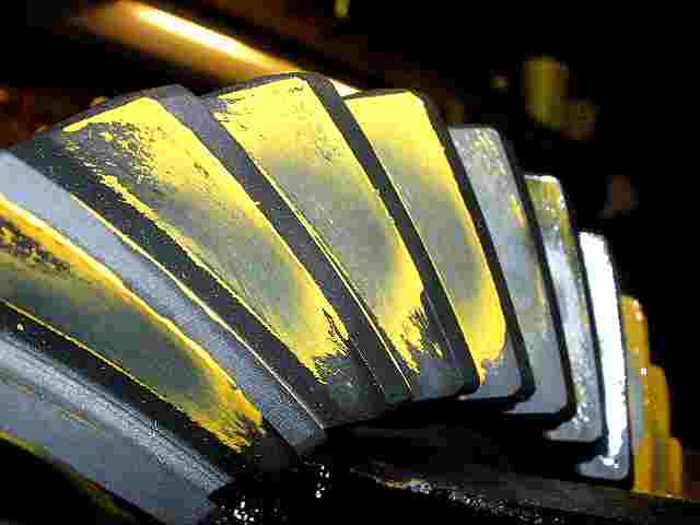
A final paint check...drive. Looks great. |
|
coast. |
|
drive side on pinion. |
|
reverse paint...drive side |
|
coast. |
|
Medium strength blue Loctite on the lock tab bolts... |
|
10 ft/lbs. |
|
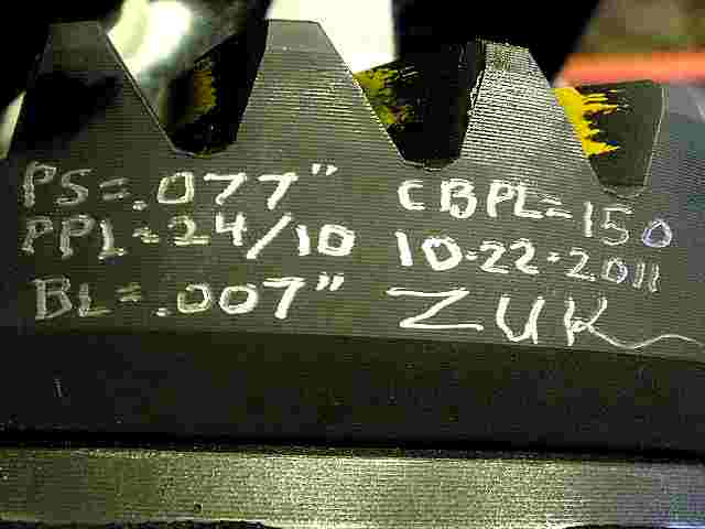
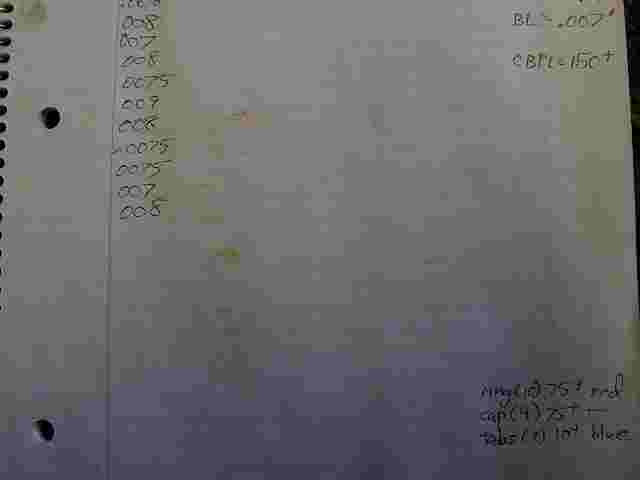
I think it's a good idea to inscribe the specs I used on the ring gear and date code it. |
|
Again, sorry about the jpeg quality. It's just barely readable. That's what 89% jpeg compression will do. |
|
... |
|
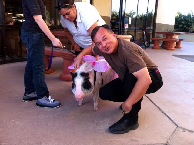
Oh ya....Aaron came over to pick up his diffs with his wife and we decided to go out for a bite to eat. This little piggy with the 2 people in the background showed up close by our table so I had to introduce myself. She seemed unimpressed. No matter what I said to her, it was like in one ear and out the other. |

|