|
Harrop Electric Locker Install on Eric's '94 FZJ80
|
|
(59 BIG pics loading)
|
|
MARCH 27 2016
|
|
|
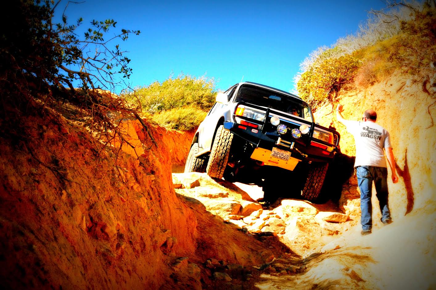
Eric is the proud owner of a 1994 FZJ80 with a mild 115,000 miles on the clock so far.
So far it has an OME 2.5" lift, Toyo 315 AT tires, and an ARB bumper with a
Warn 8000 pound winch.
|
|
|
|
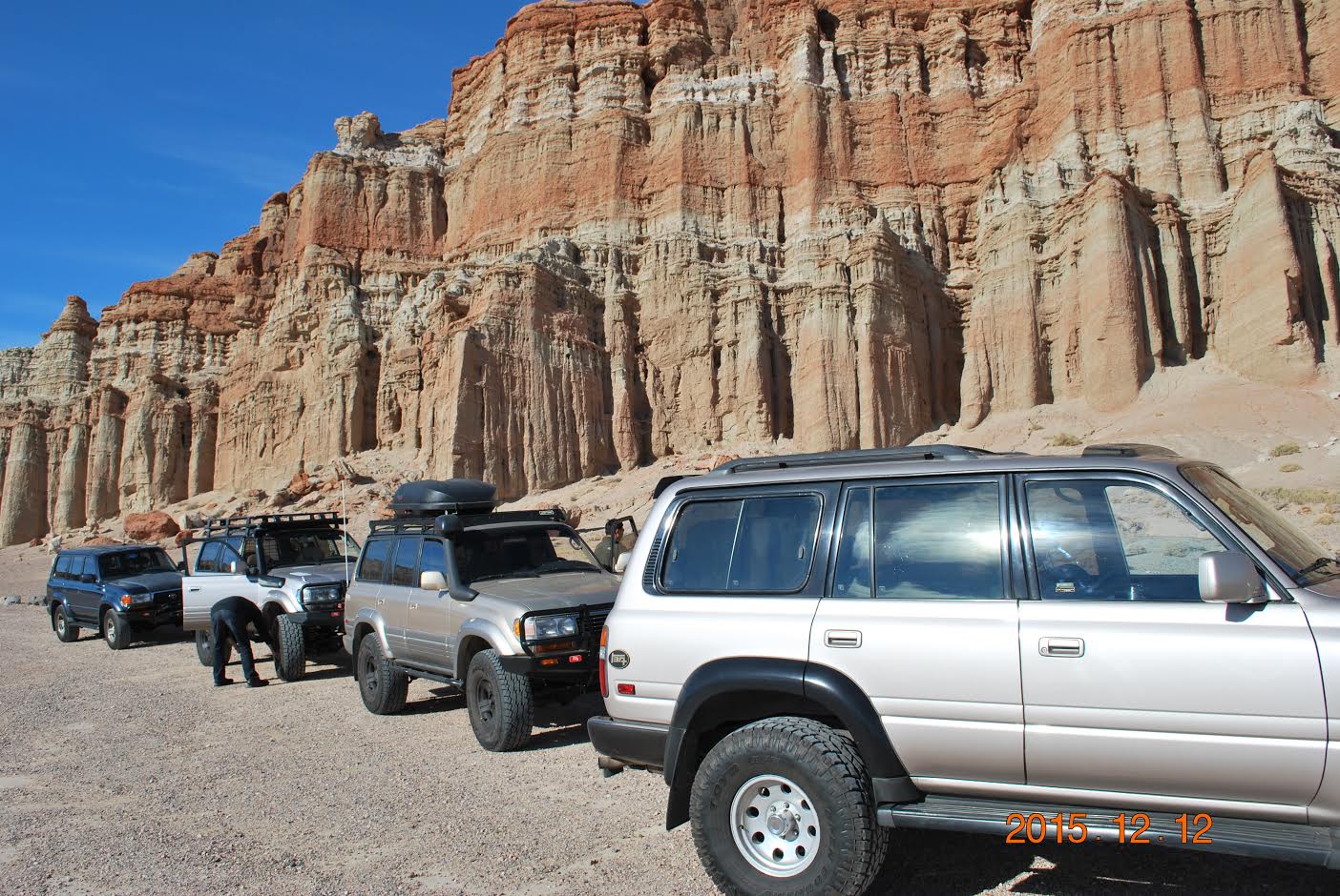
This trail was out of Red Rock state park in California. Eric was there with
3 other MUD members (NLXTACY, Qball, Dr Gill).
|
|
|
|
|
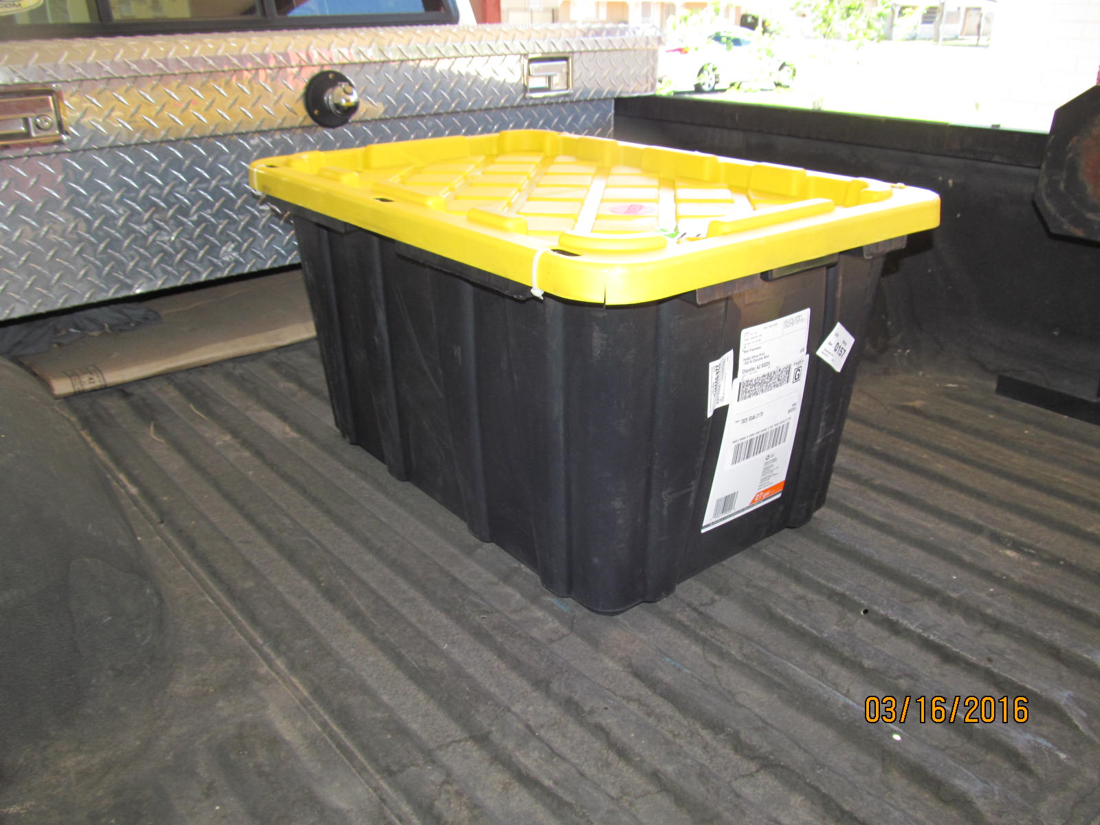
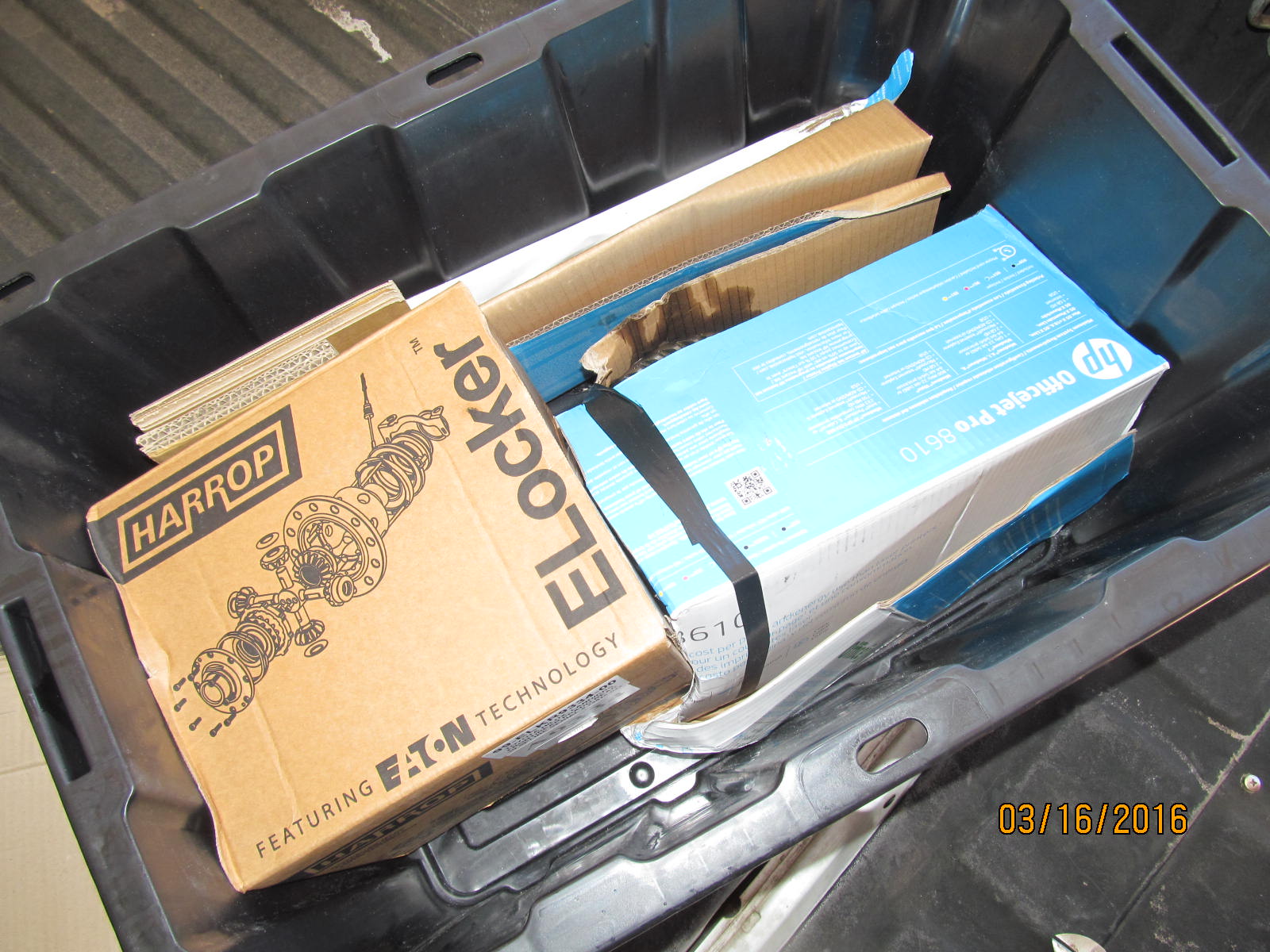
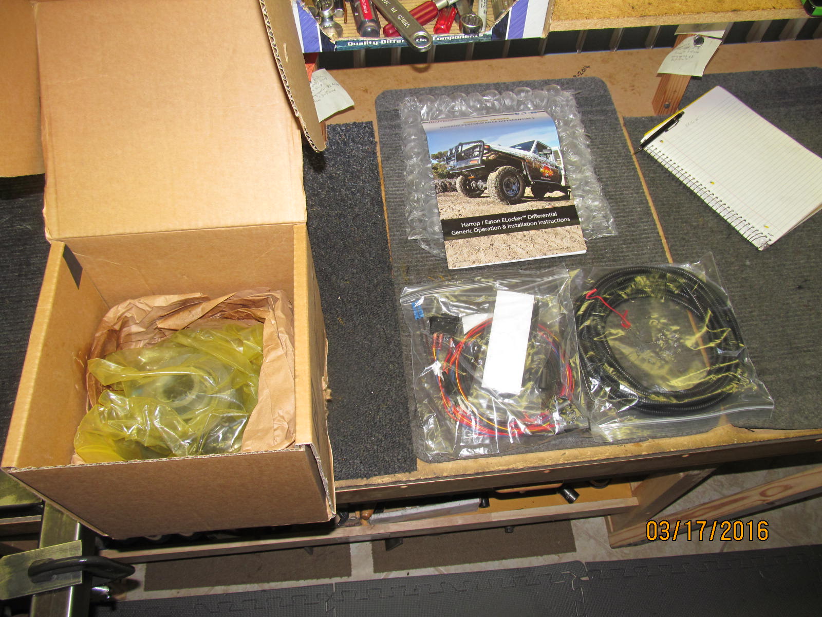
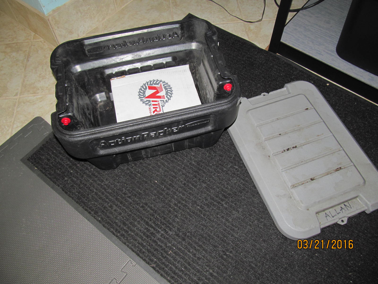
Picked this up at the nearby Fedex Office Print and Ship Center a mile away from me.
|
|
|
|
|
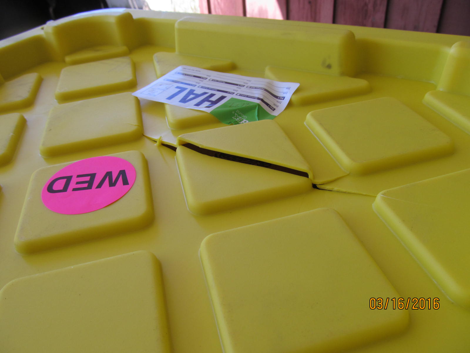
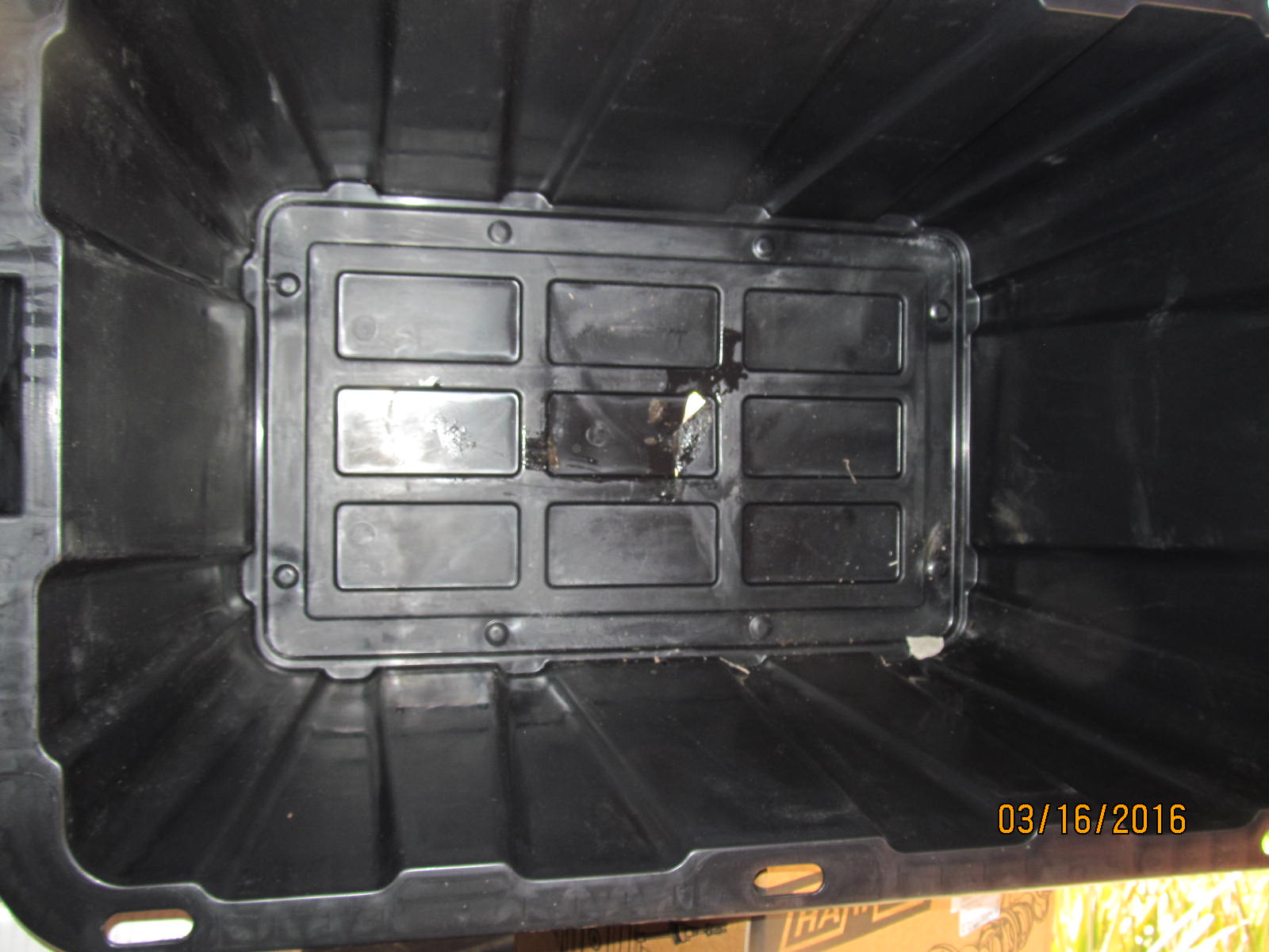
Even these heavy duty totes can give way sometimes.
|
|
|
|
|
The cardboard wrapping around the 3rd was "light"....
|
|
|
|
|
...and had something to do with this.
|
|
|
|
|
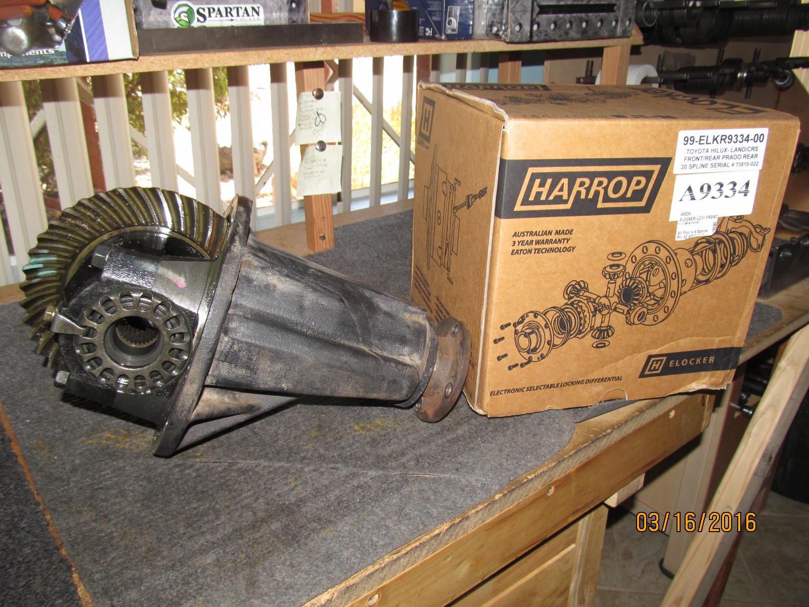
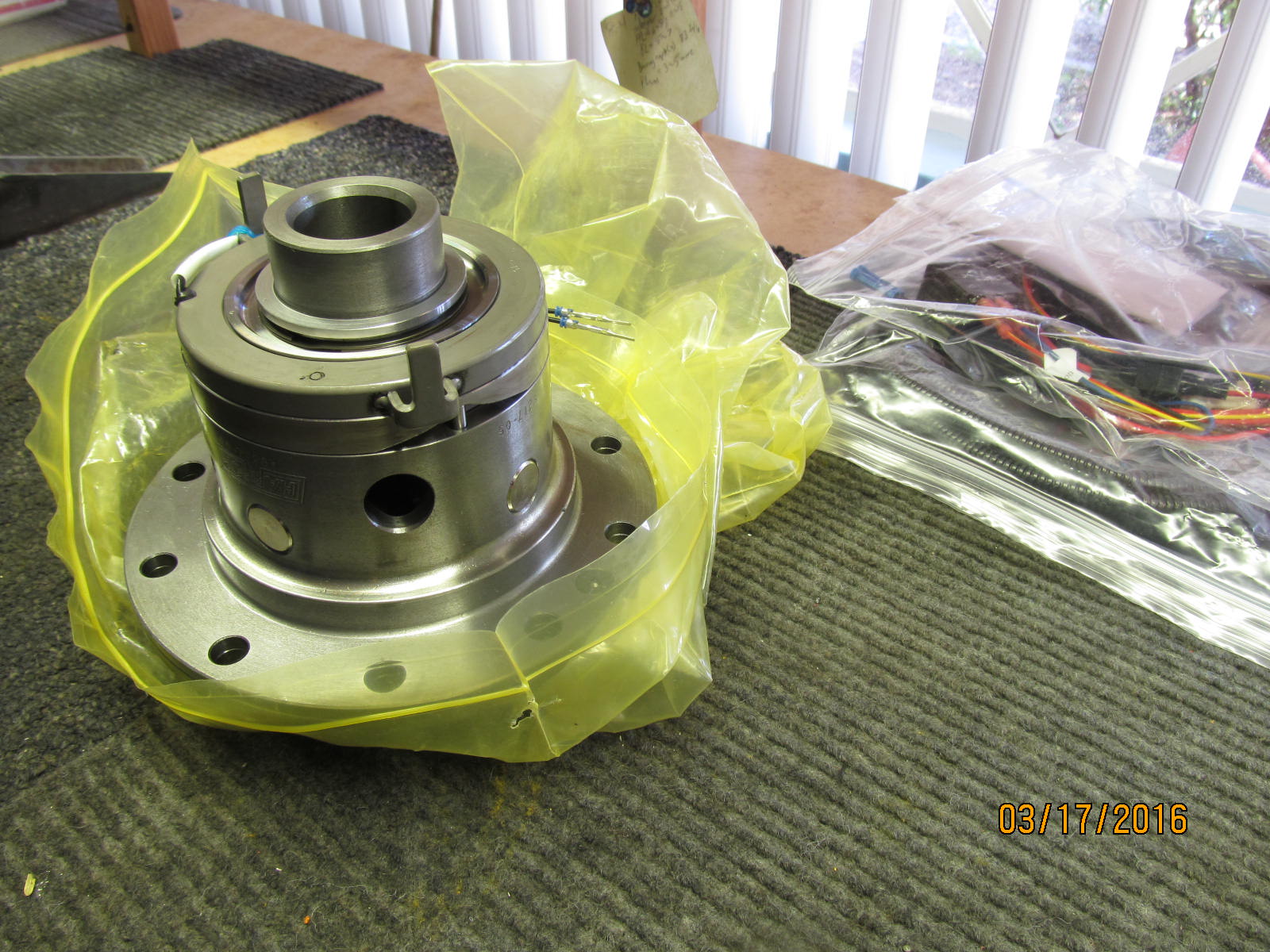
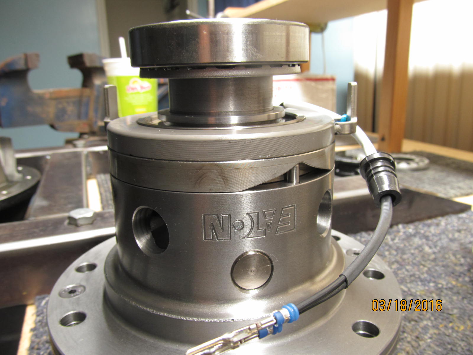
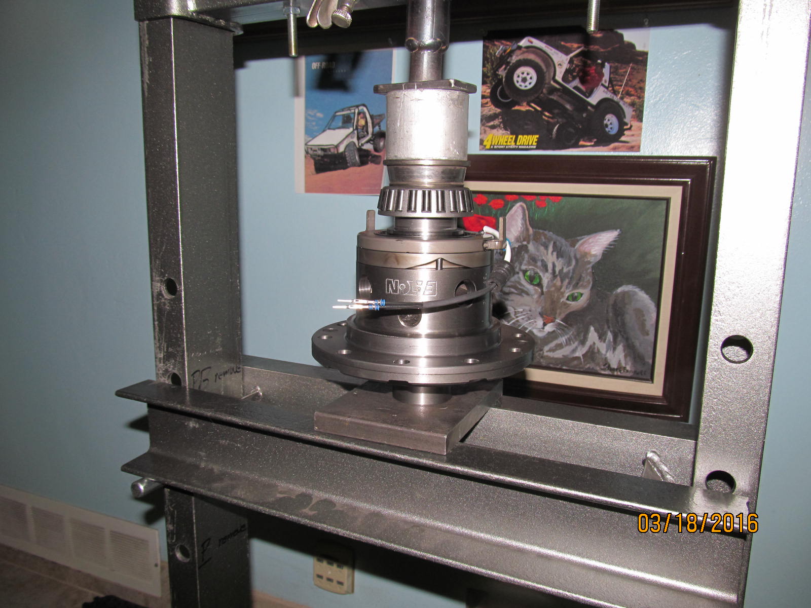
Open hi-pinion 8" front 3rd and the Harrop electric locker on the right.
|
|
|
|
|
.............
|
|
|
|
|
.................
|
|
|
|
|
A nice, heavy chunk of well machined Aussie steel.
|
|
|
|
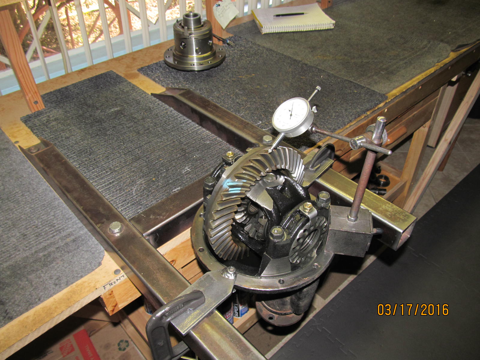
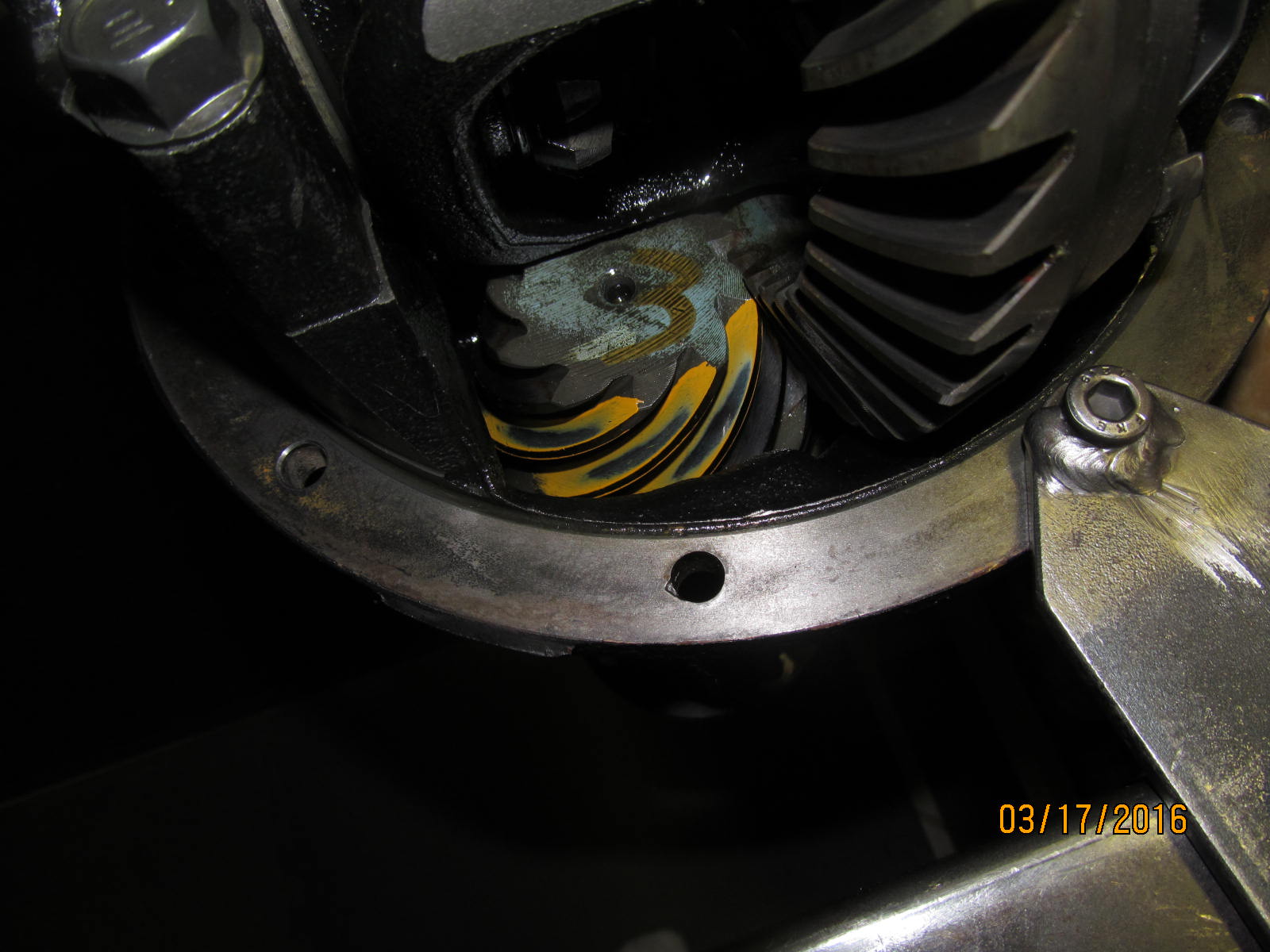
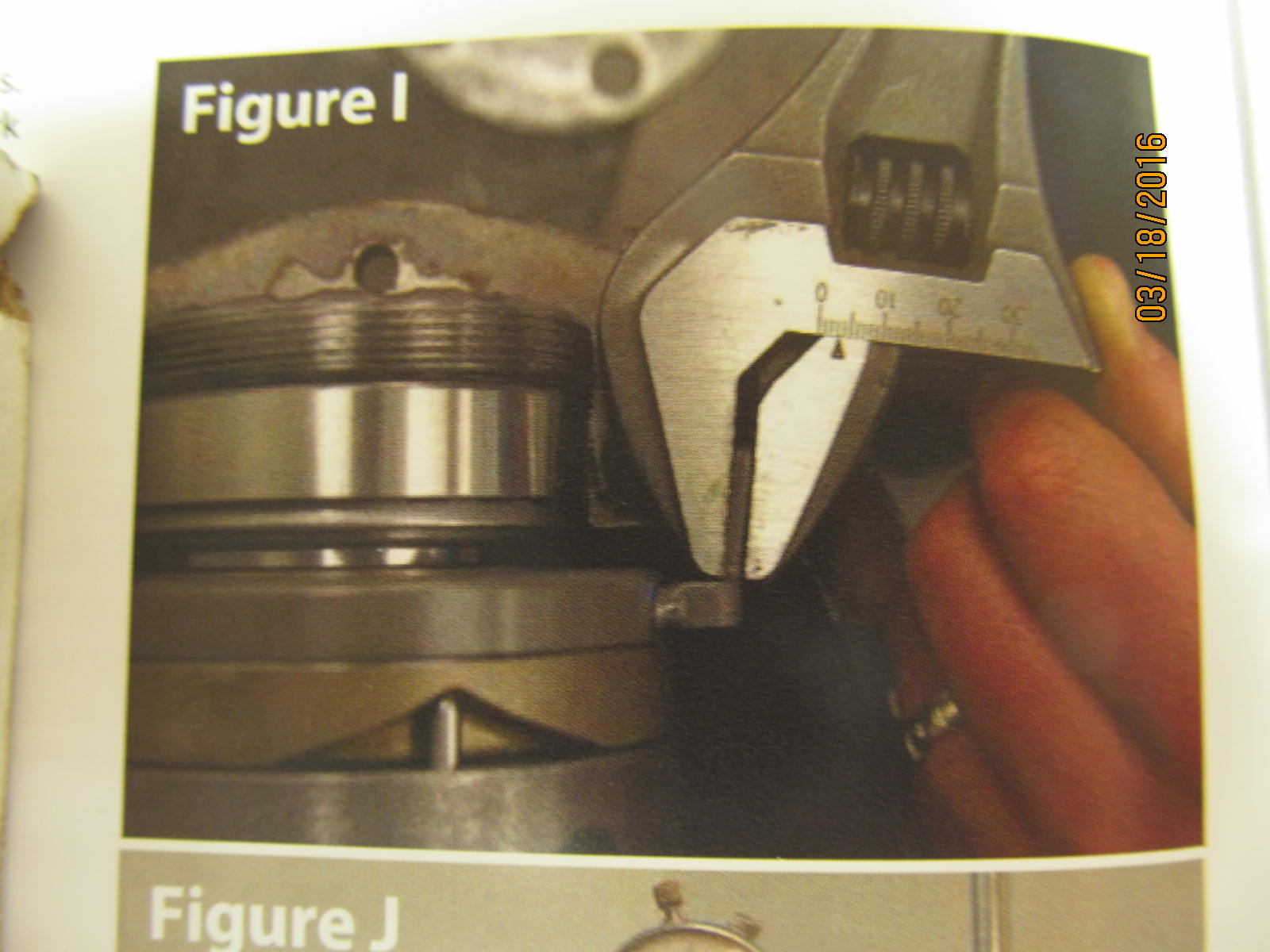
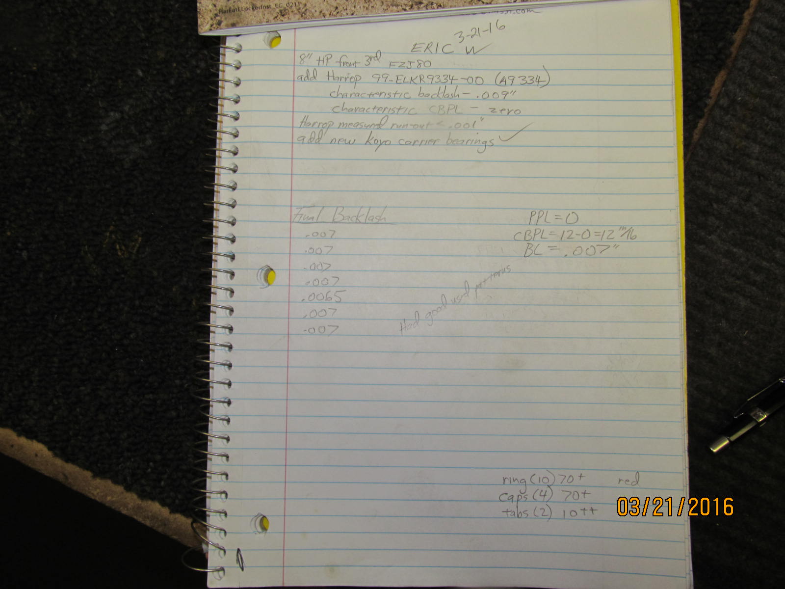
Characterizing Eric's factory 3rd....noting that his backlash was a little wide at .009". These reverse cut
factory 410 V6 gears will be re-used, of course.
|
|
|
|
|
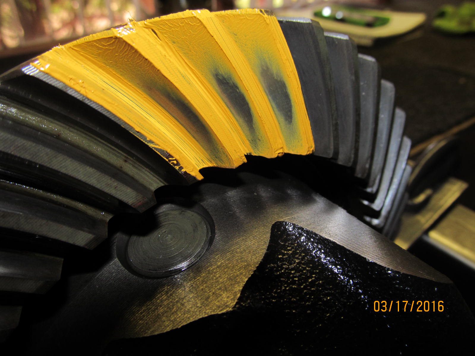
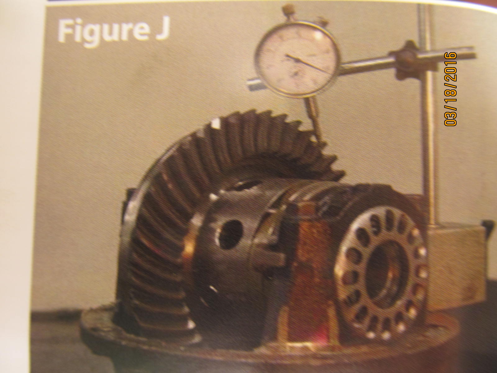
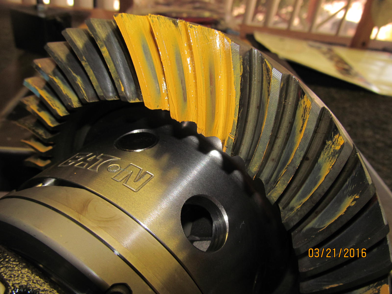
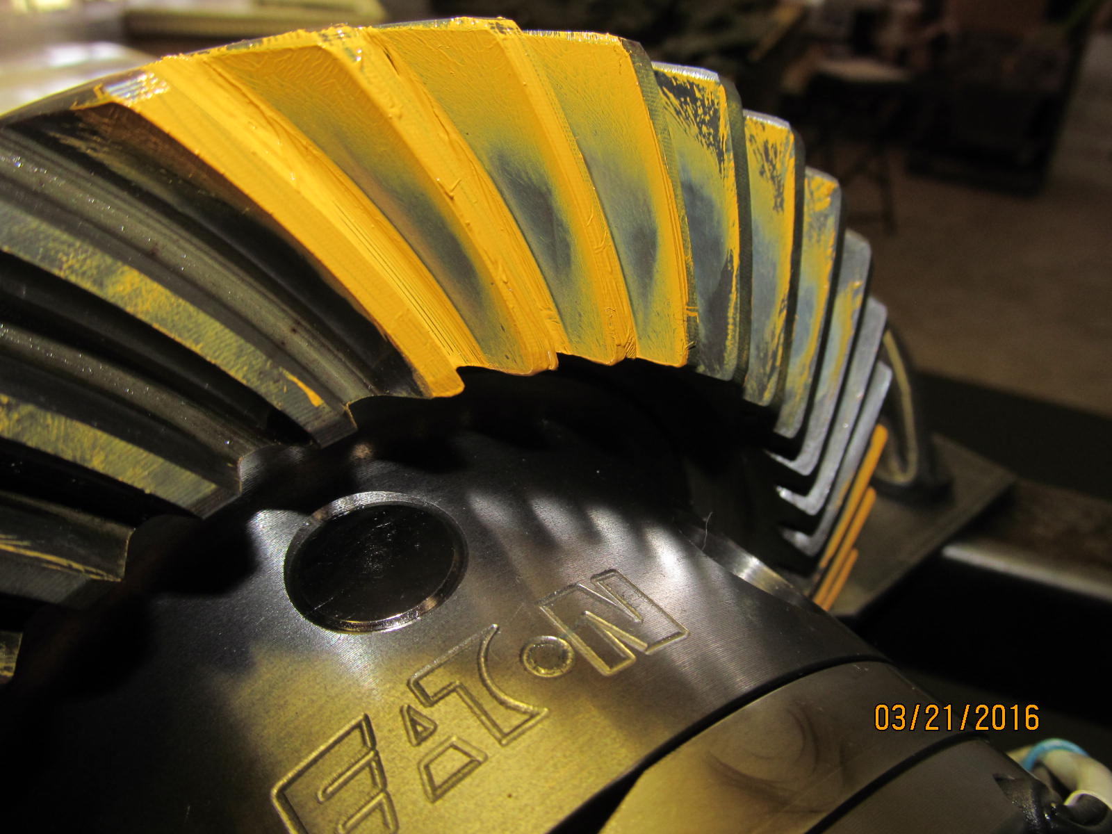
A pattern check shows the gears have been riding in a good zone to the present. Pattern is almost classical.
|
|
|
|
|
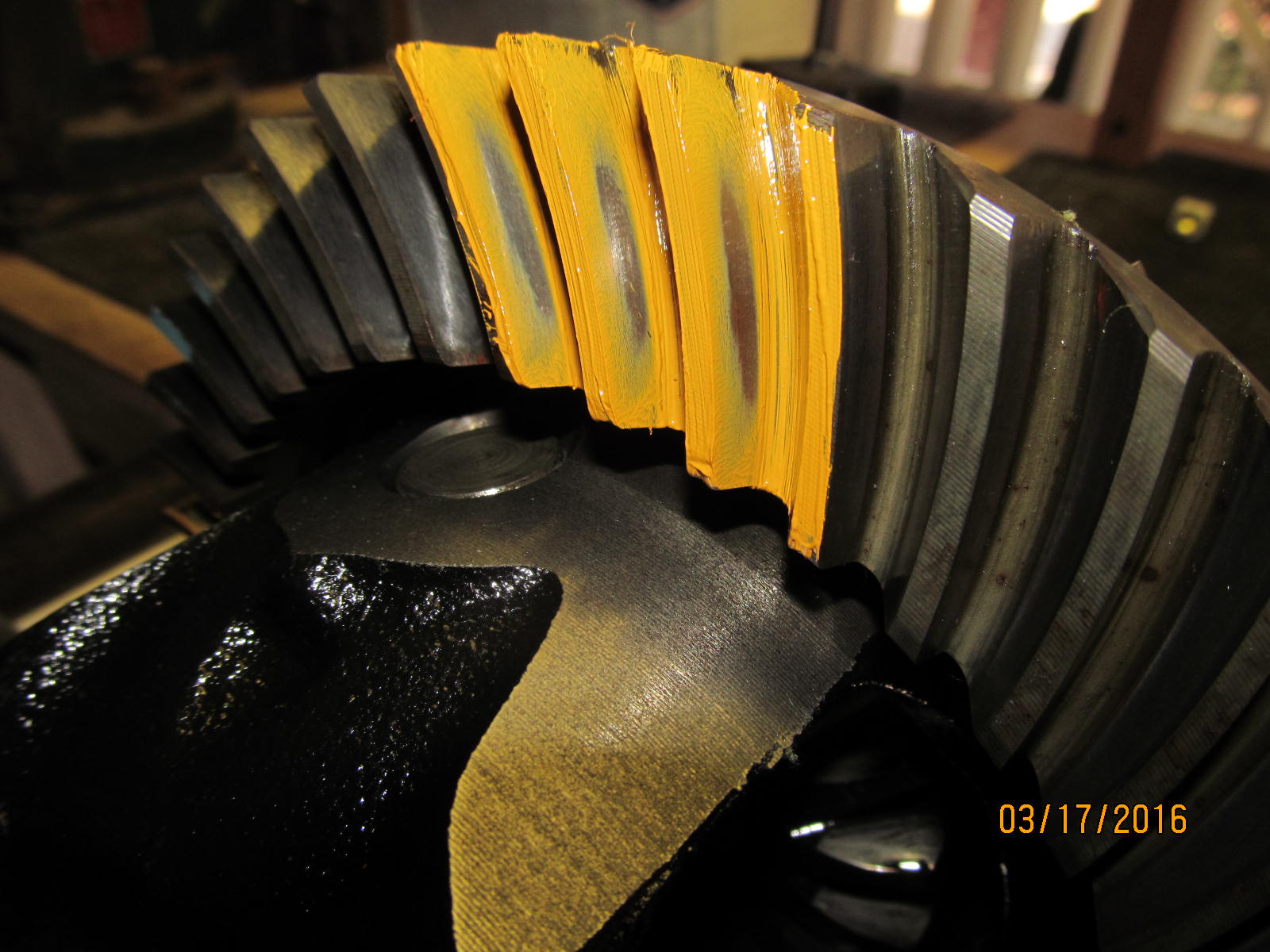
Nice solid pattern on the coast side.
|
|
|
|
|
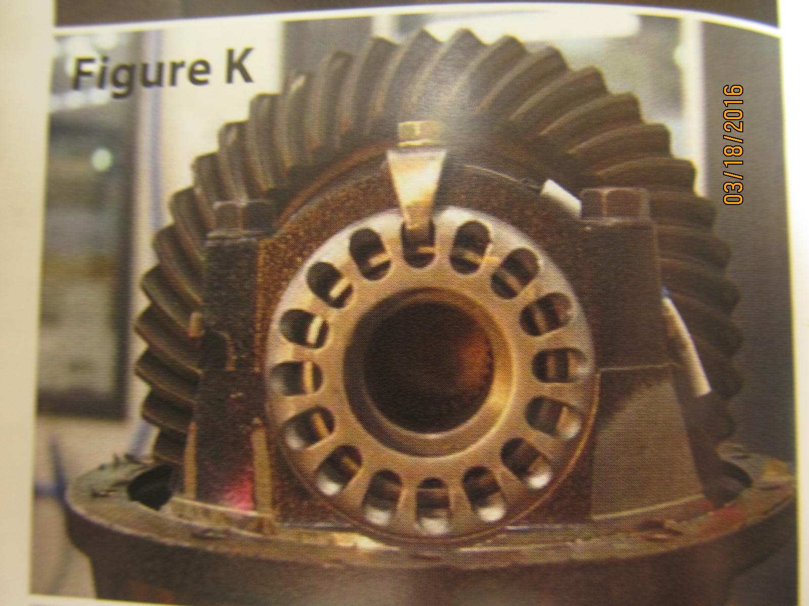
The drive side on the pinion tooth looks great.
|
|
|
|
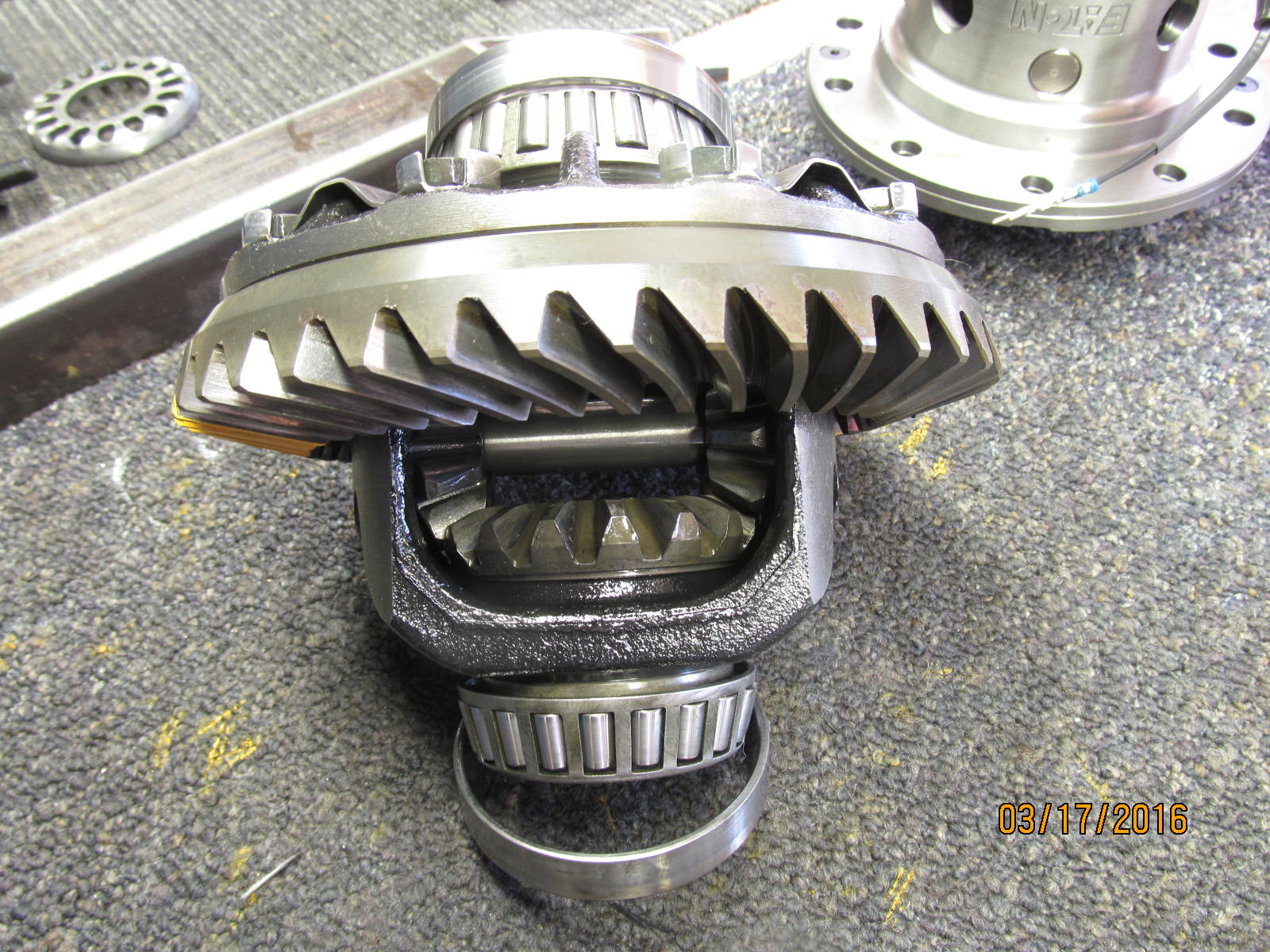
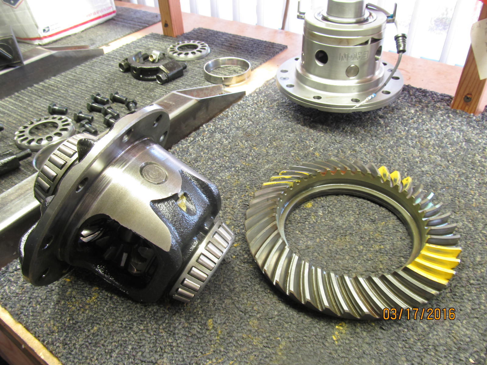
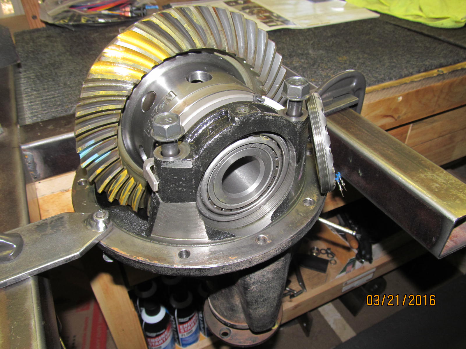
Carrier is removed from the 3rd and, since new carrier bearings will be used, only the ring gear itself needs
swapping over.
|
|
|
|
|
Ring is removed.
|
|
|
|
|
New carrier bearing to be pressed on.
|
|
|
|
|
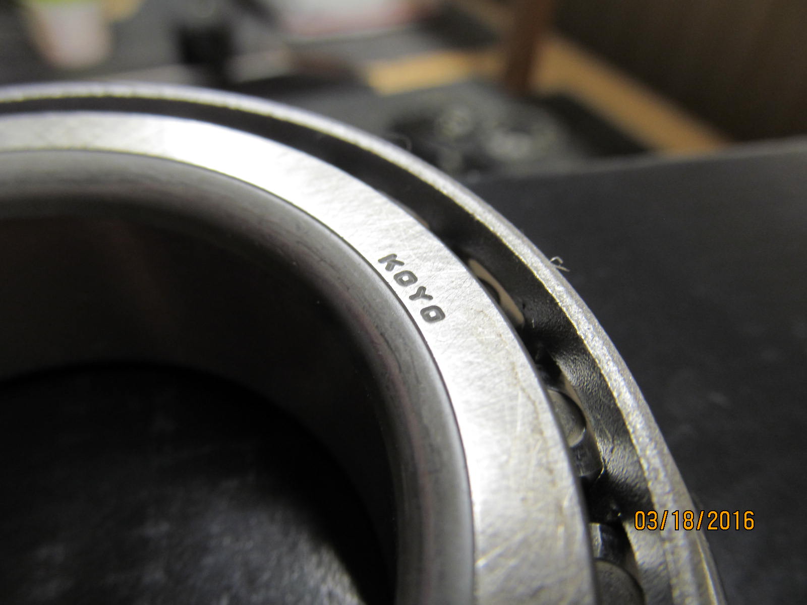
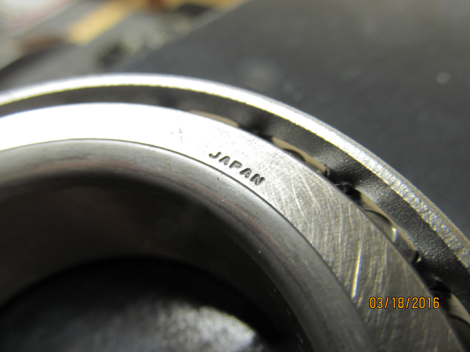
Genuine KOYO carrier bearings.
|
|
|
|
|
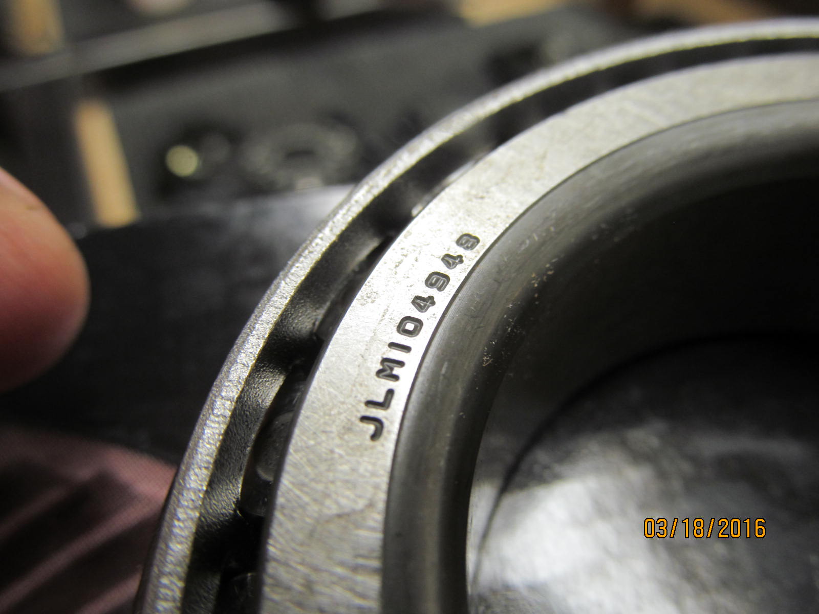
JLM104948
|
|
|
|
|
----------
|
|
|
|
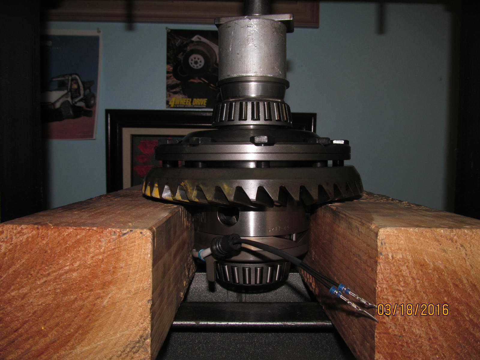
New bearings were a good, tight fit onto the Harrop. This is just a basic HarborFreight 12 ton press
and has been more than enough press for the 15 years of online gear installs that I have accumulated.
|
|
|
|
|
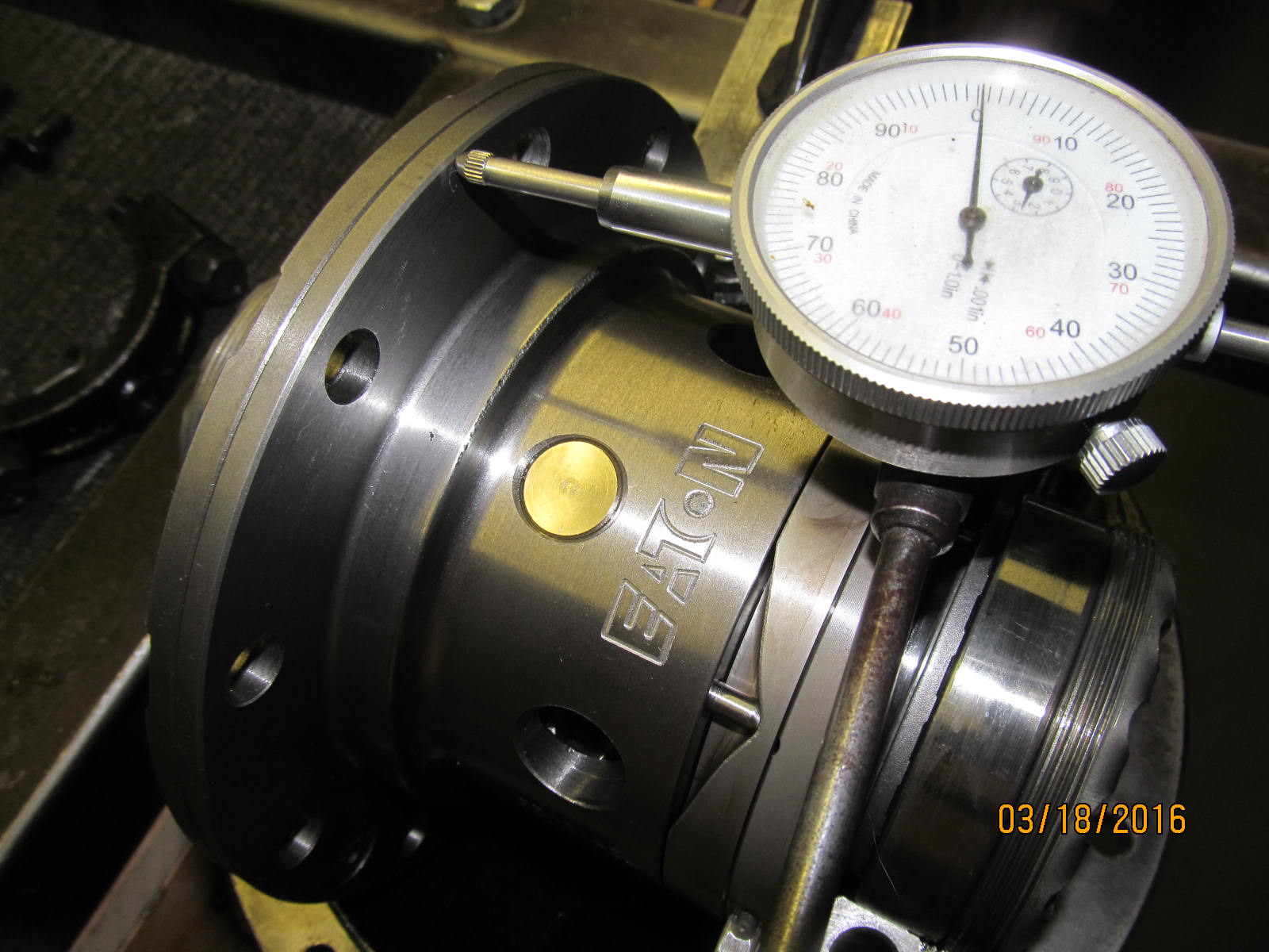
A quick check of the runout on this new Harrop shows it to be less than .001"
|
|
|
|
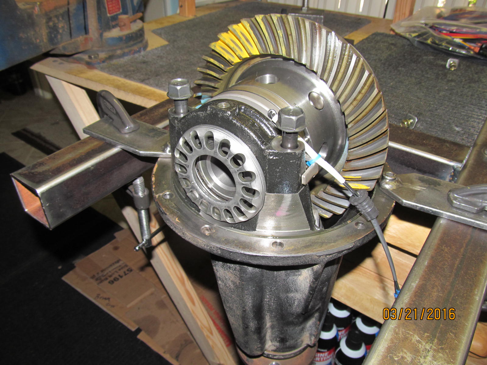
A very tight fit for the ring gear. Very careful eyeball alignment is required to get it to seat dead-nuts
over the ring bolt holes.
|
|
|
|
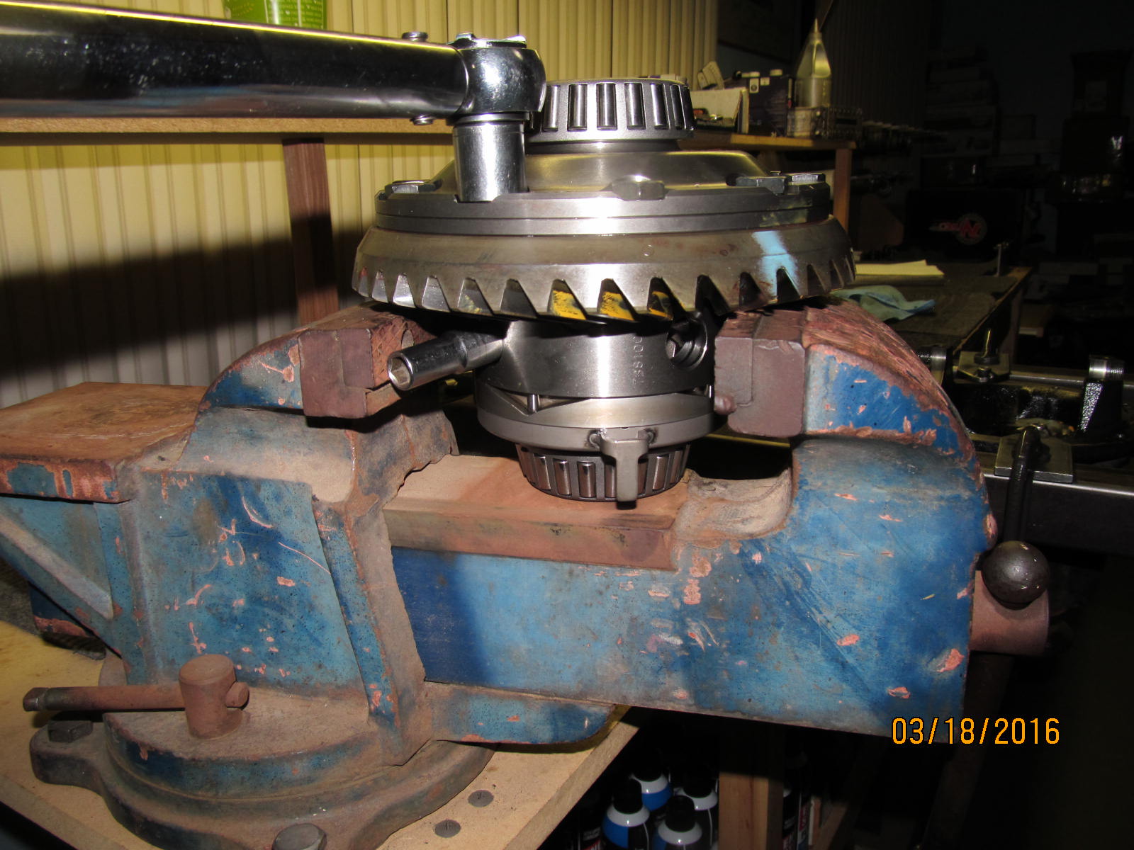
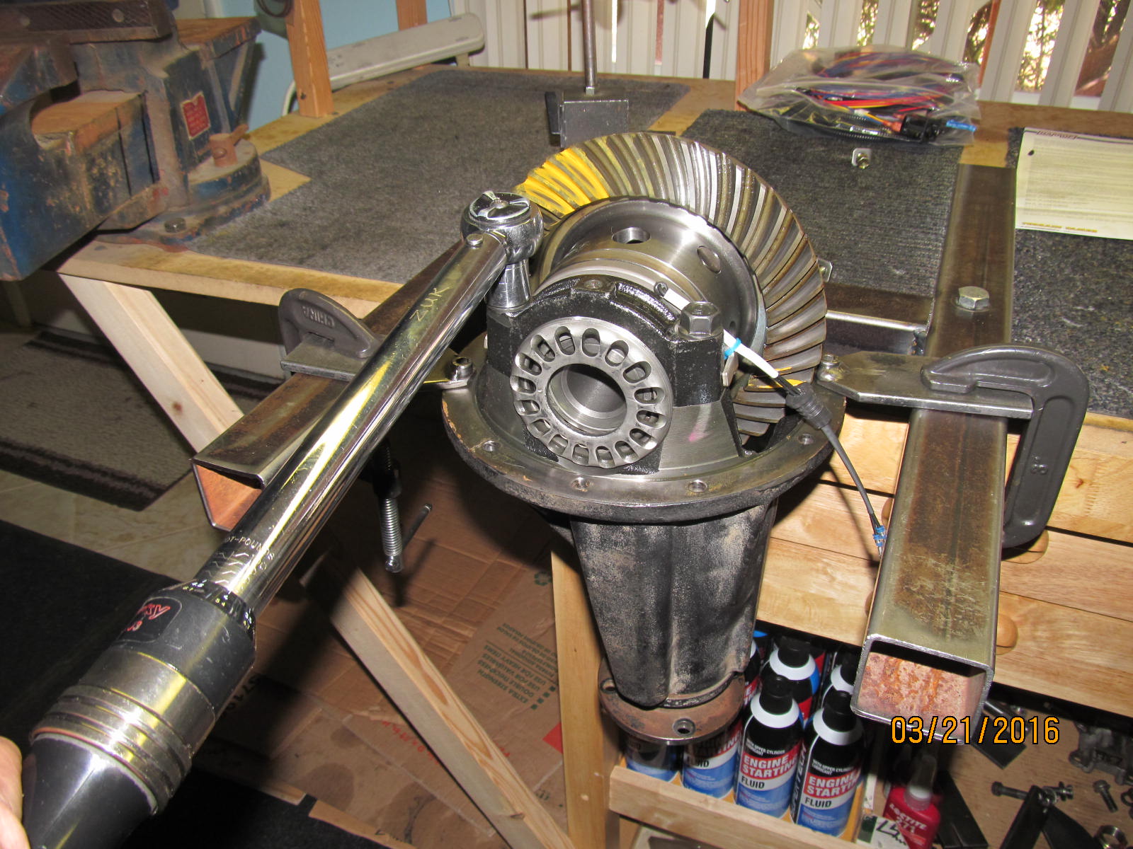
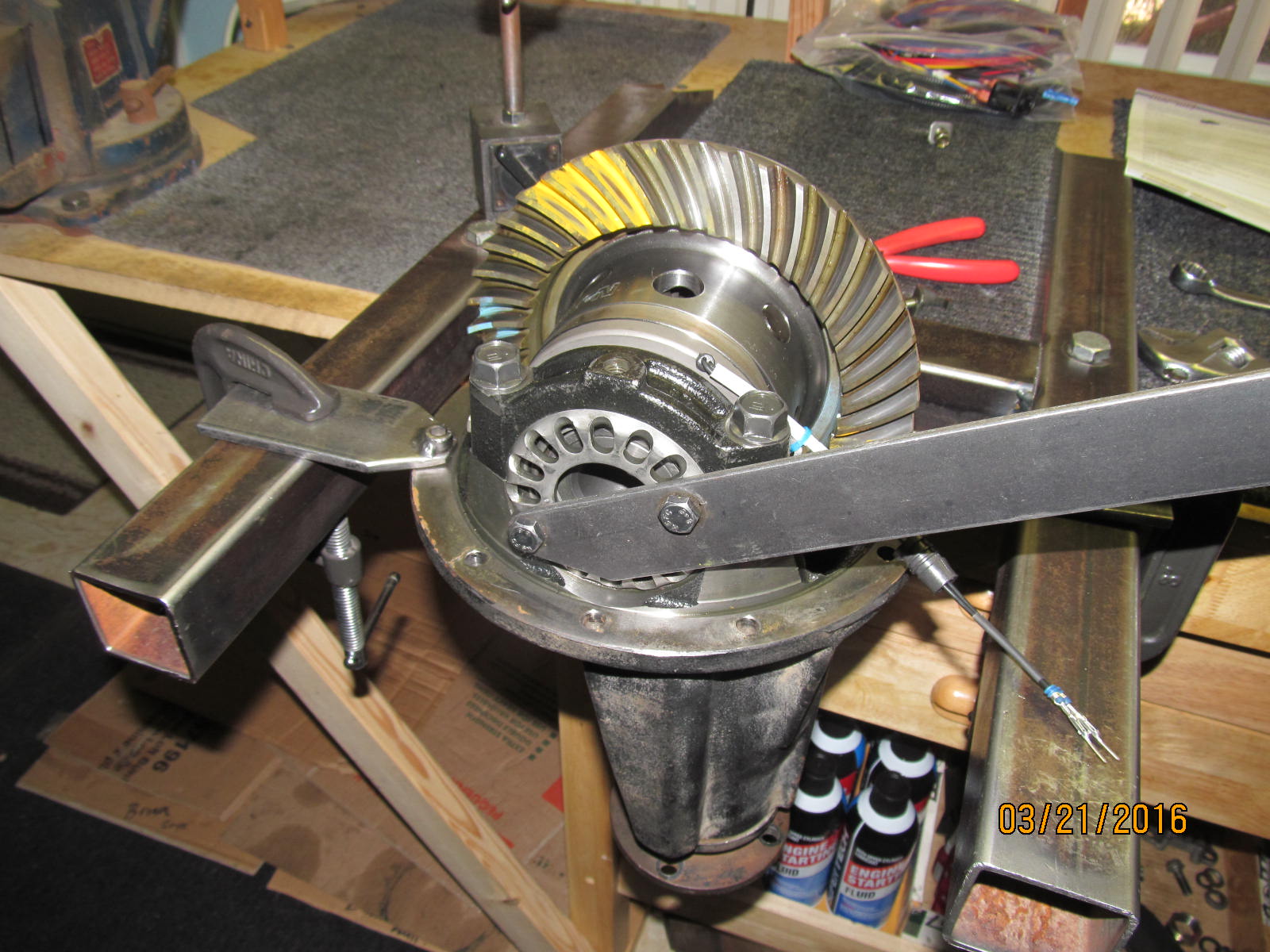
As usual....70 ft/lb and red Loctite. The Harrop case is not actually being scarred/compressed
by the vice jaws... a select socket at each end placed in the holes will prevent the case
from turning while the jaws themselves only make casual case contact.
|
|
|
|
5 snapshots from the included instructions. This one showing to use a large crescent wrench to bend
the tabs out to increase the radial play to the target 2mm.
|
|
|
|
|
This one of setting the backlash.
|
|
|
|
|
These wheels control both backlash and the preload on the 2 carrier bearings.
|
|
|
|
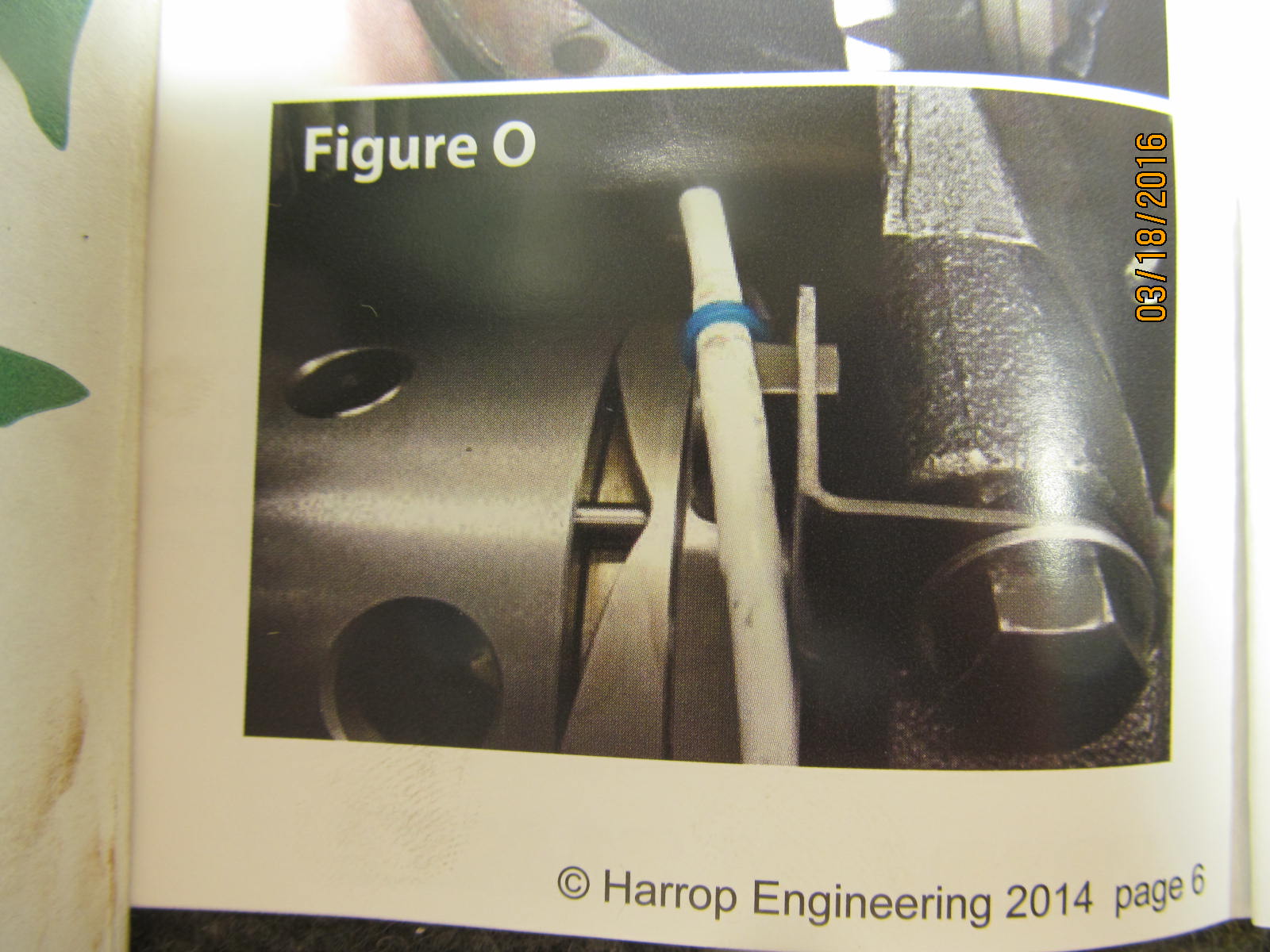
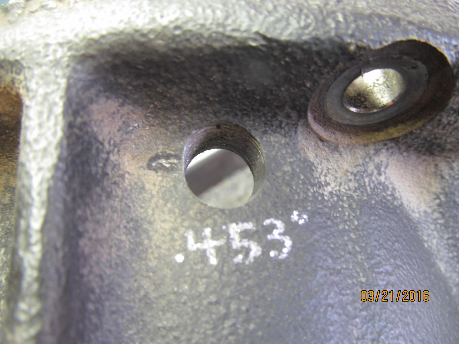
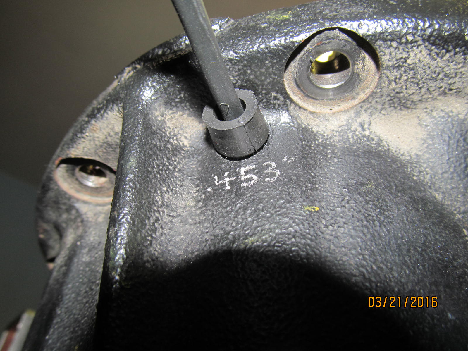
Picking a good close place to drill the .453" hole. Notice no anti-rotation bracket for this
style of 3rd member. This is the same style we are doing in this write-up.
|
|
|
|
|
And other styles may have the anti-rotation bracket as shown above.
|
|
|
|
The trick is to push to the left and bend to the right at the same time. That way, the 2 welds
are not stressed as much.
|
|
|
|
|
They say about 2mm of up/down freeplay is desired and that is what I have here right now.
|
|
|
|
|
Marking the spot to be drilled....making sure it is in a clutter free zone.
|
|
|
|
|
29/64 or .453"
|
|
|
|
|
It was just easier to slide the upper bearing cap in place, thread the 2 bolts in.....
|
|
|
|
|
....and THEN thread the large adjuster wheel on.
|
|
|
|
|
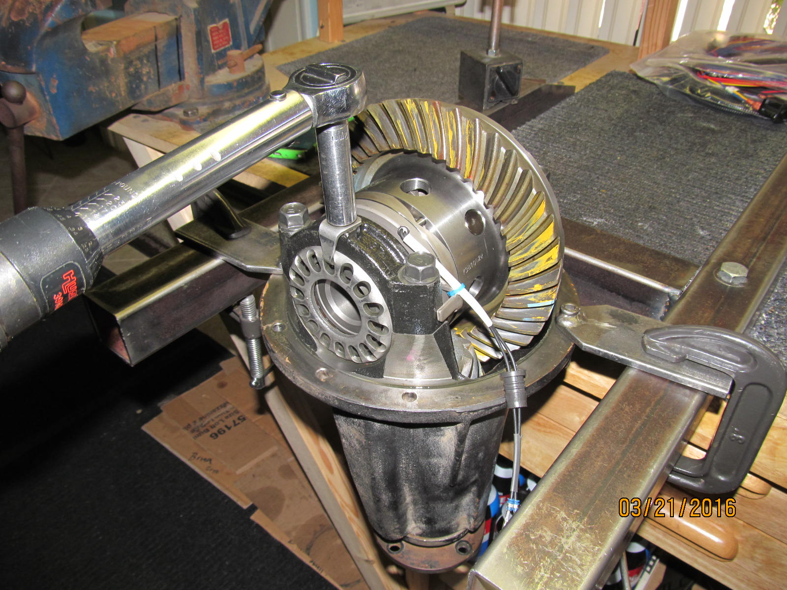
70 ft/lb on both.
|
|
|
|
|
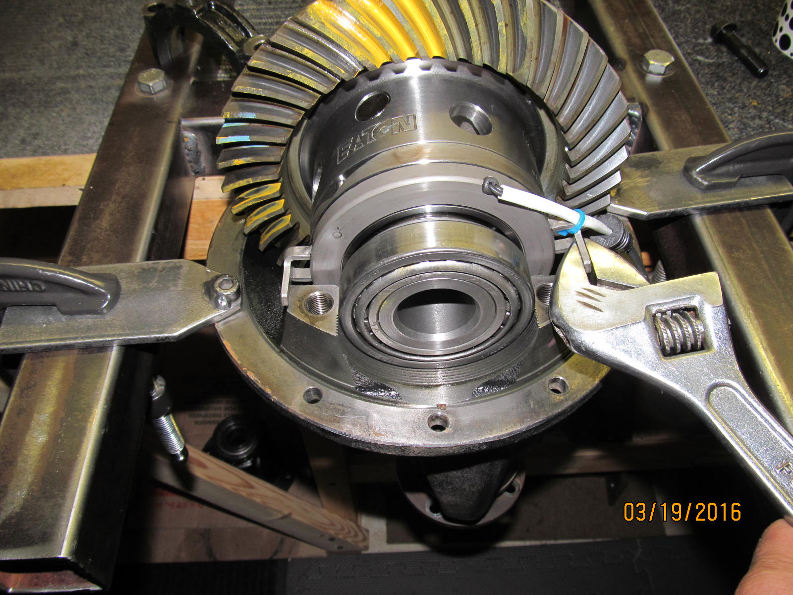
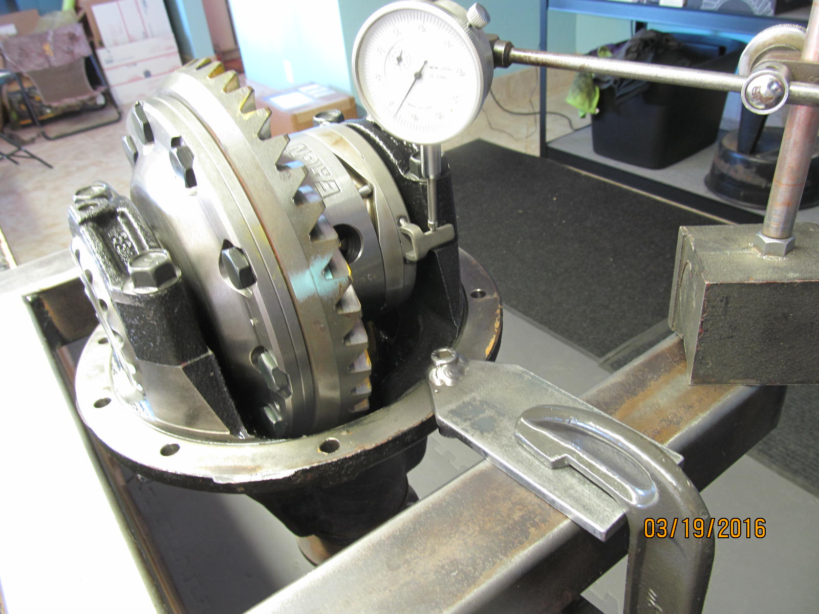
Using the spanner wrench of your choice, tighten both adjuster wheels....
|
|
|
|
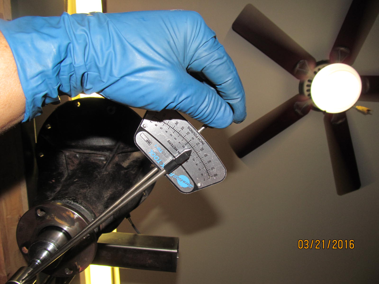
...til the CBPL is in the desired zone...
We are not touching the pinion end in this install and I noted earlier that while the pinion has no actual
slop up/down wobbleness to it, it has no actual pinion bearing preload.....PPL is 0.
So, whatever we measure here shown above is 100% all carrier bearing pre-load.
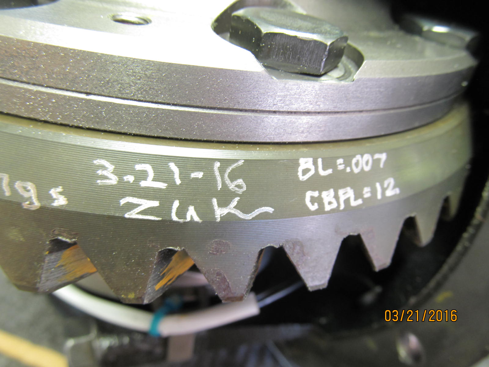
12 inch/pounds start torque for cbpl.
|
|
|
|
|
Backlash is measured and recorded in 7 places around the ring gear and is a very solid and consistent .007".
|
|
|
|
The 2 lock-tabs are tightened to 10 in/lb. The anti-rotation tabs are double checked and have
about 2mm of up/down play.
|
|
|
|
|
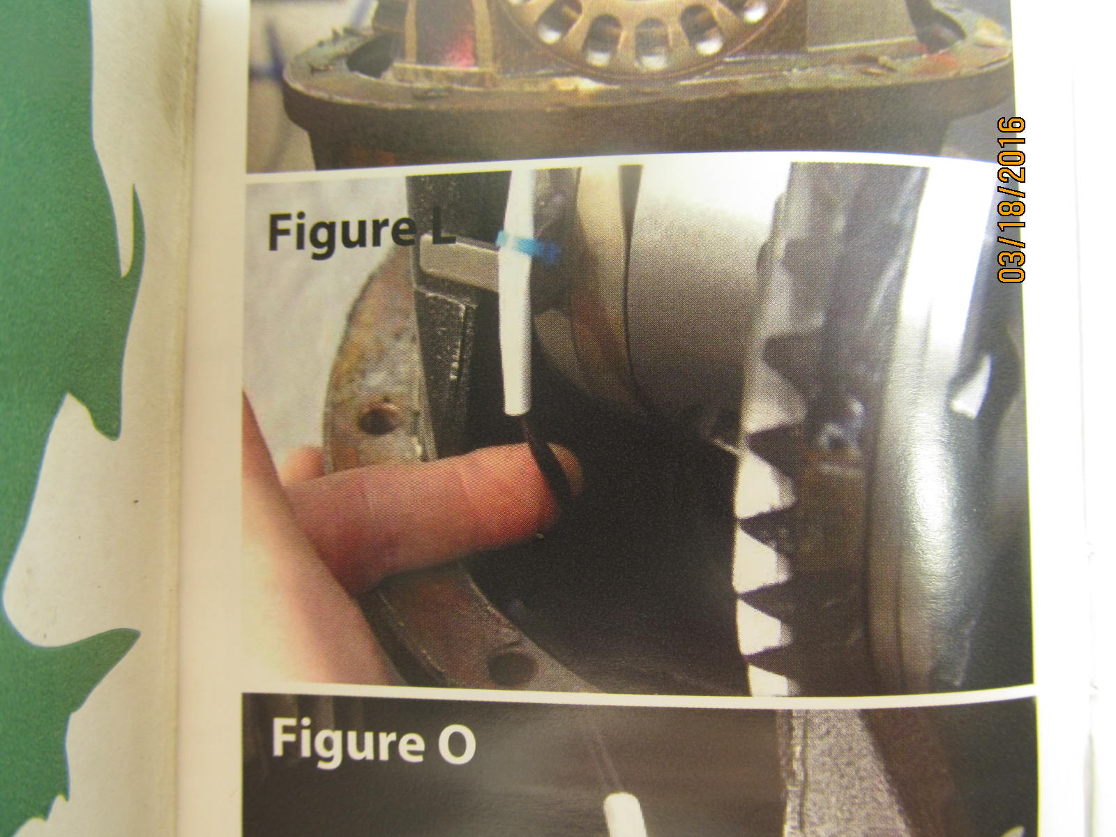
Drive side ok.
|
|
|
|
|
Coast is ok.
|
|
|
|
|
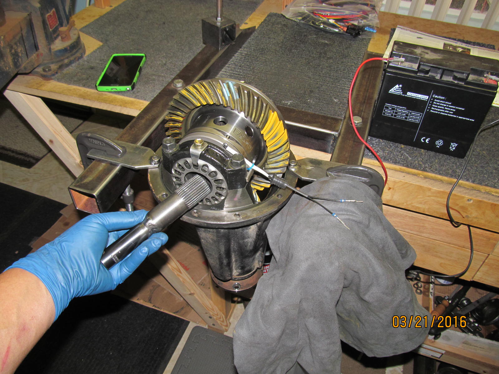
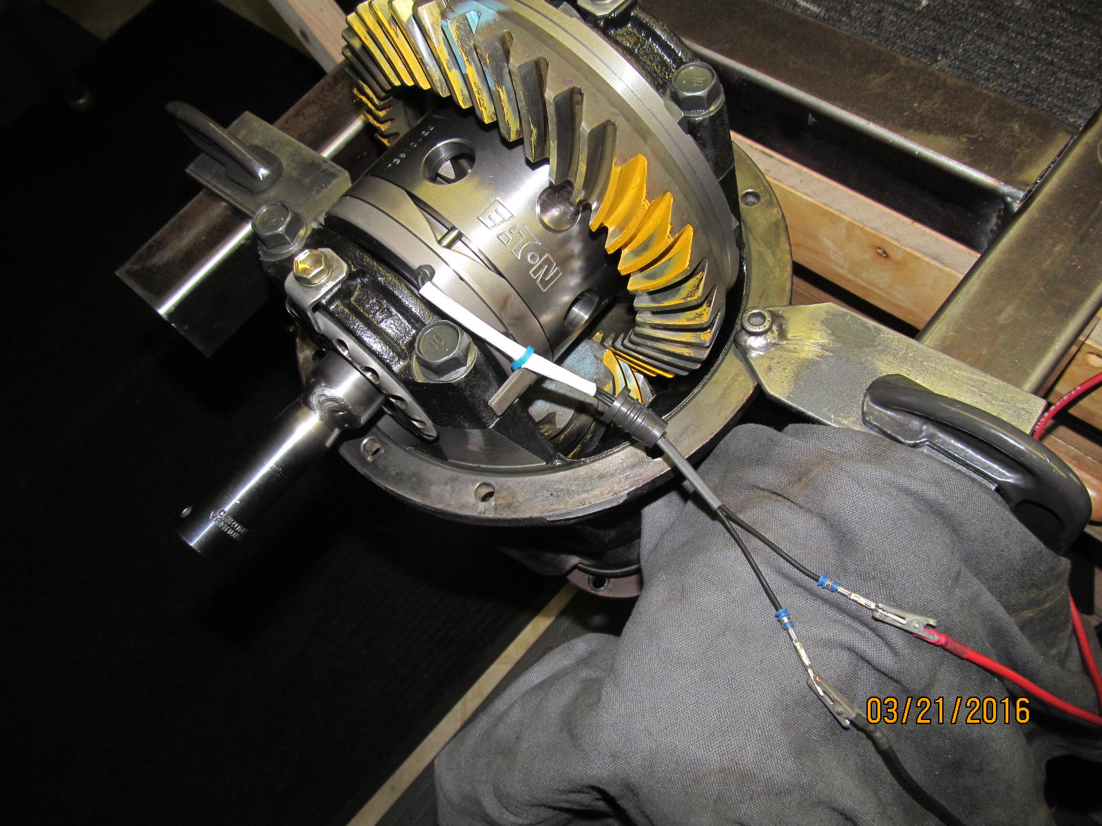
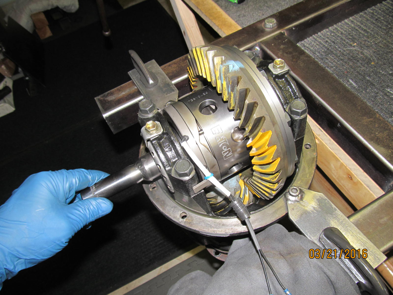
Testing to observe the locker in operation. A 12v portable source is close by.
|
|
|
|
|
The sidegear spins freely as shown here (not locked).
|
|
|
|
|
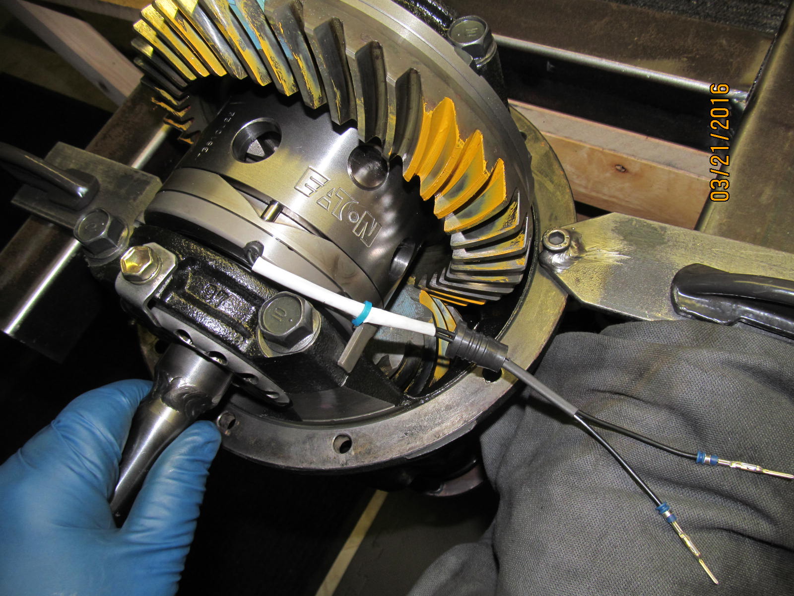
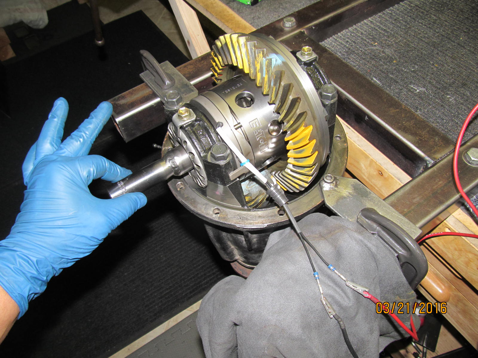
12v is applied (no polarity) and a slight clunk was heard...very faint though.
|
|
|
|
|
The locker is still not locked because I can turn the side gear easily as shown here.
|
|
|
|
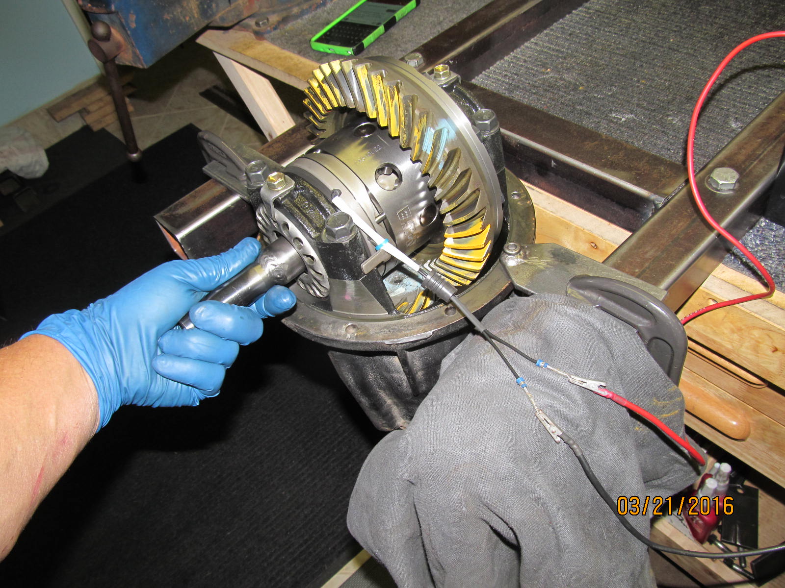
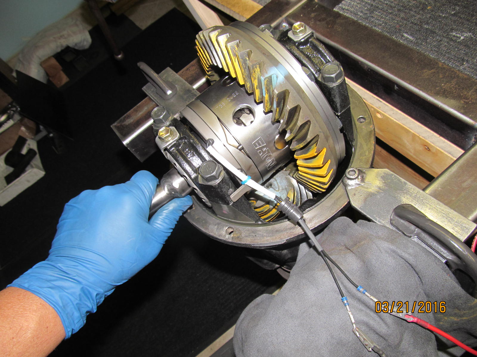
But as soon as the pinion shaft(driveshaft) is turned, the pin starts to walk up the ramp and now it
really is locked.
|
|
|
|
|
Continue turning the pinion shaft and the pin is fully up the ramp and still locked, of course.
|
|
|
|
|
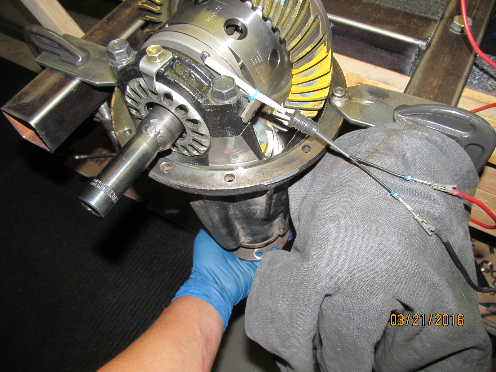
Reverse the pinion shaft direction and the pin starts to go down the ramp again but still appears to be locked.
|
|
|
|
Continued turning the pinion shaft until the pin is at the bottom of the ramp and now the
side gear will turn freely(not locked up). This all happens in a very small amount
of pinion shaft rotation.
|
|
|
|
|
Continue turning the pinion shaft and it locked up again.
|
|
|
|
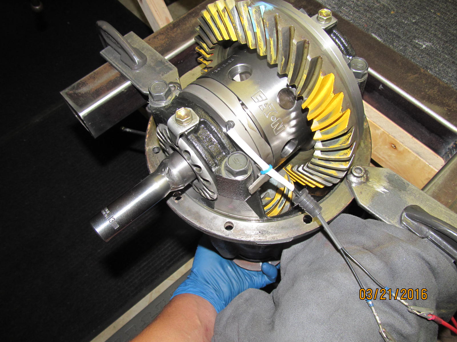
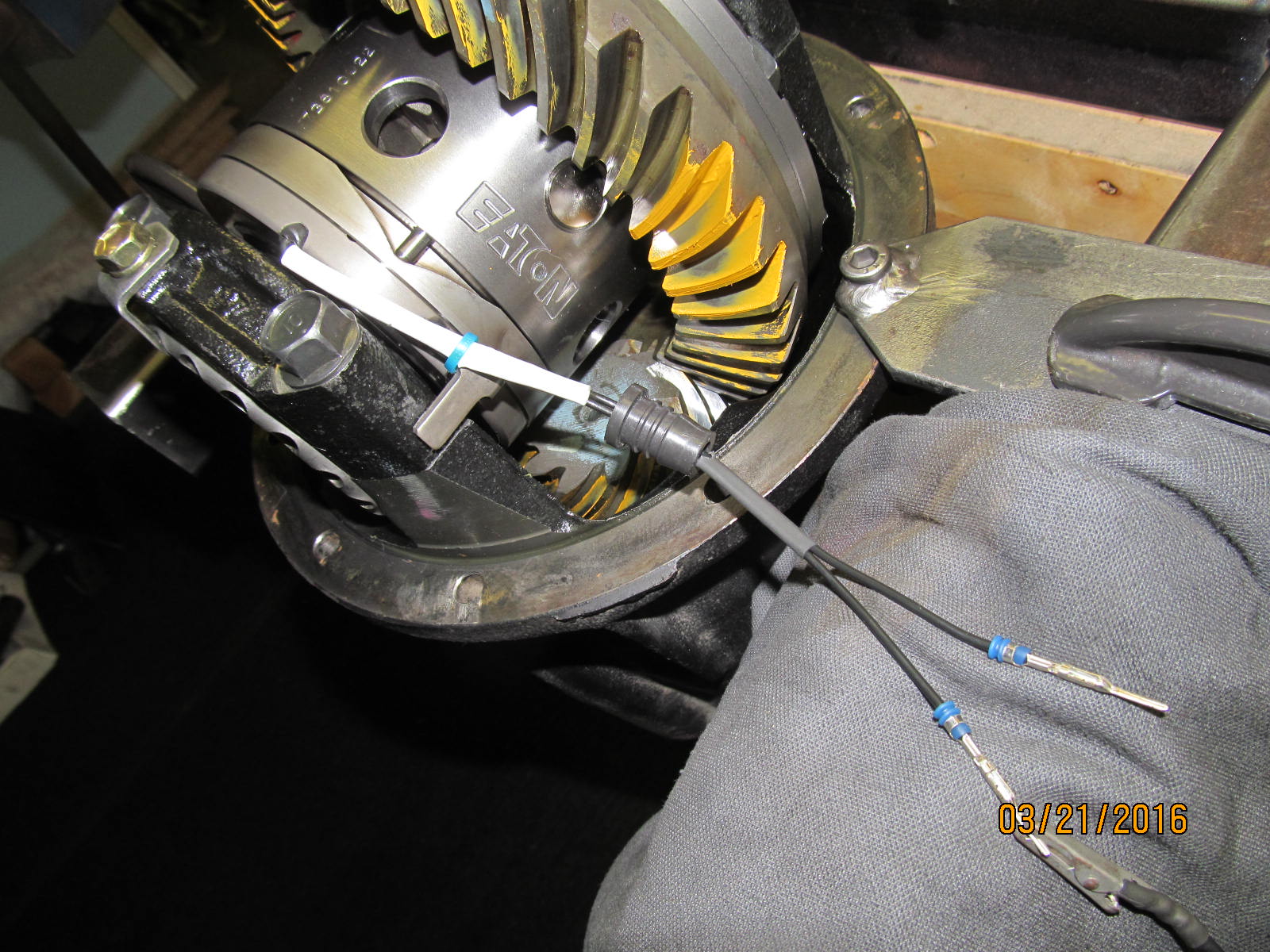
Now remove the 12 volts and the pin immediately snaps to center on its own and the locker
is back to open mode(unlocked).
|
|
|
|
|
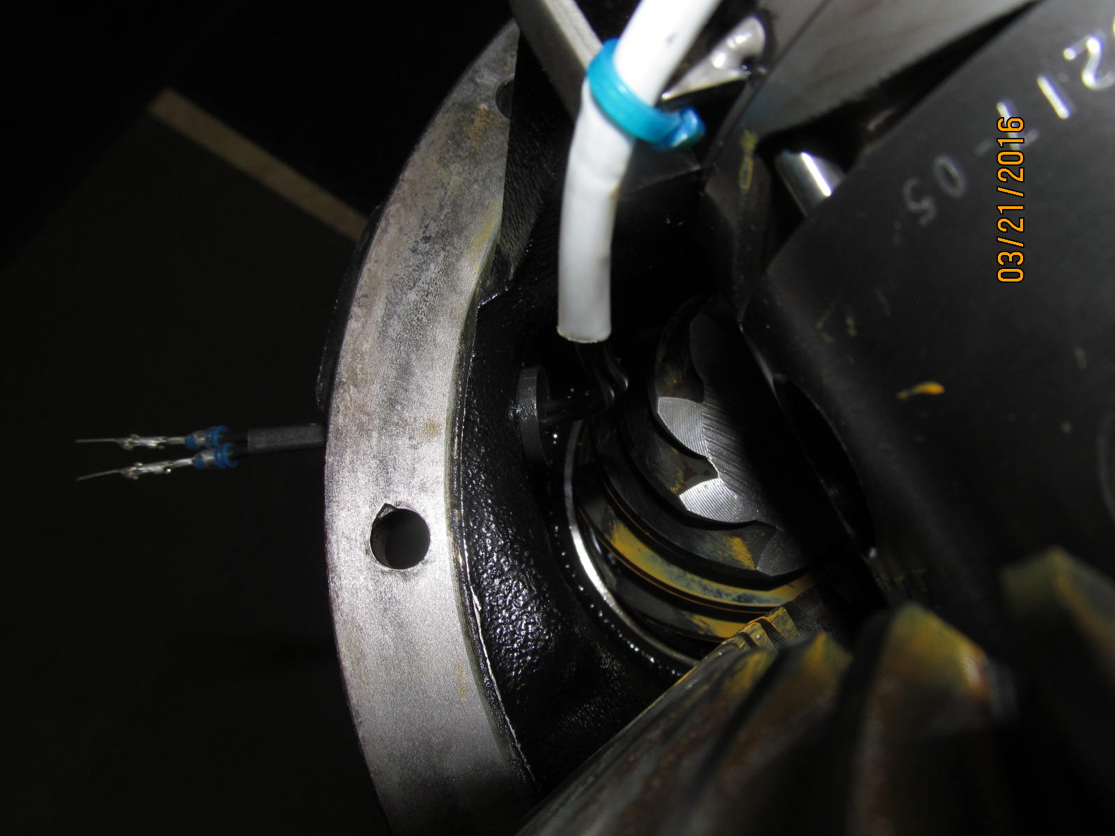
Now to push the rubber grommet all the way in which results in some special words. All I can say is good luck.
|
|
|
|
I have strong fingers and it took my strength and a little creativity to make it happen.
It would be much easier to seat the rubber grommet from the outside pushing in...and would
make future replacement of the grommet much easier in the event it started to rot/crack
from aging.
|
|
|
|
|
,,,,,,,,,,,,,,,,,,,,
|
|
|
|
|
--------------------
|
|
|
|
|
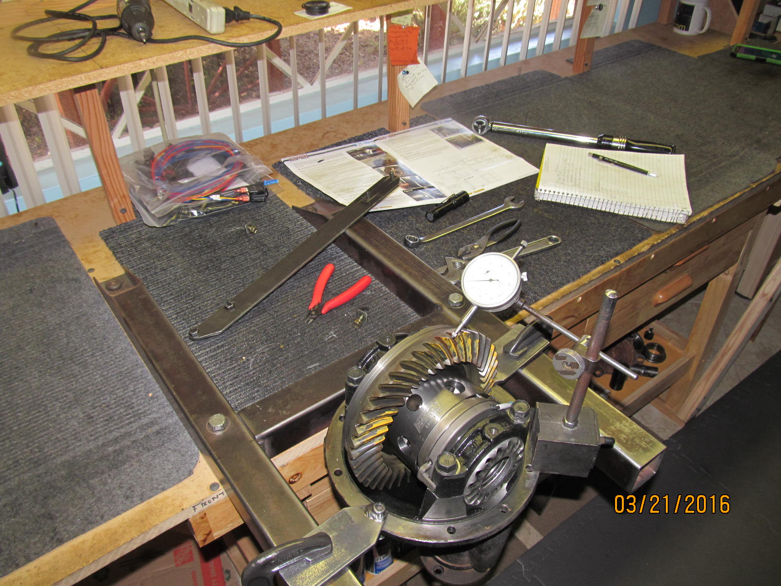
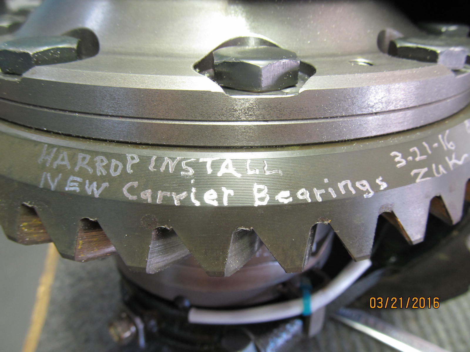
Notes taken during the install.
|
|
|
|
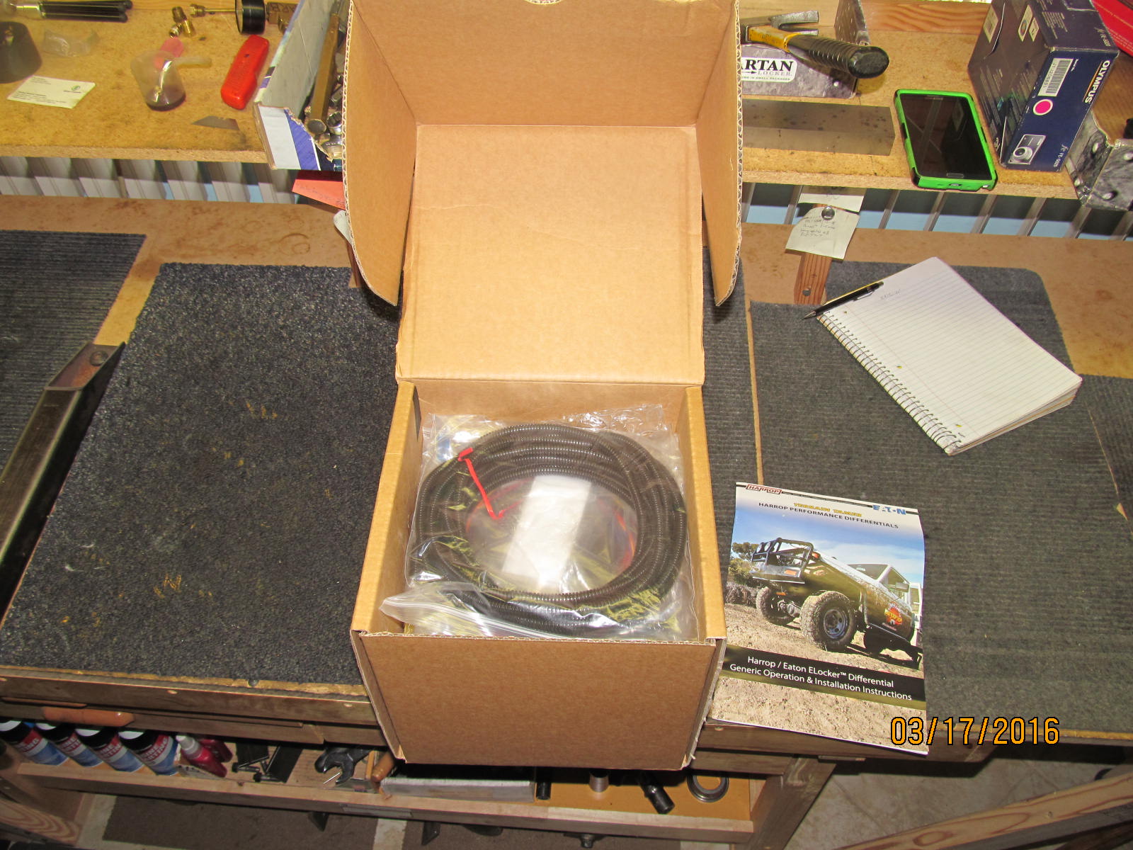
Now to pack the Harrop equipped 3rd in this "cushioned" tote and point it towards California.
Koyo carrier bearings are already included in the box
Contact Ward Harris (National importer/authorized dealer for Harrop) at 1-800-224-7801
or email info@cruiserbrothers.com
|
|
|
|

|