|
Harrop E-Locker Install for Eric's 1997 LX450
|
|
(103 BIG pics loading....give it some time)
|
|
JAN 28 2016
|
|
|
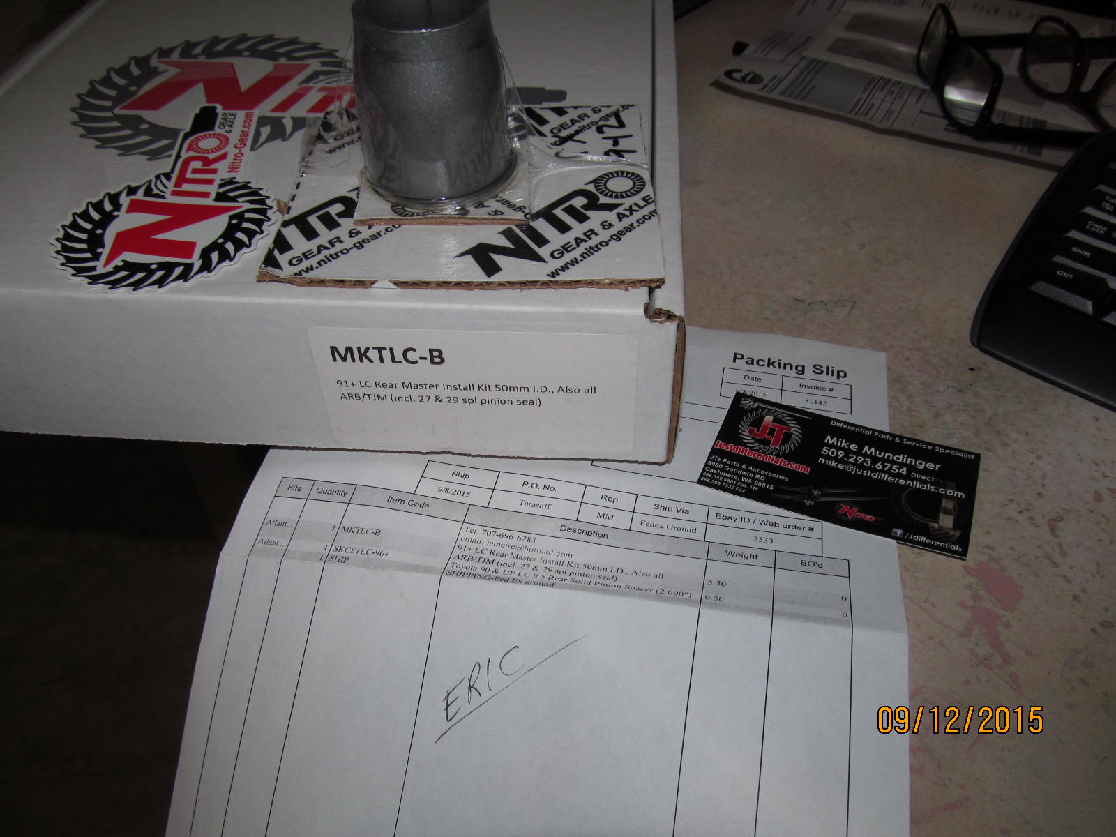
Eric had Mike from JustDifferentials send a new master install kit and solid collar.
For a Harrop install, just new carrier bearings is the norm.....but Eric figured that as long as I'm
in there now is the time to get new pinion bearings and a solid collar .
|
|
|
|
|
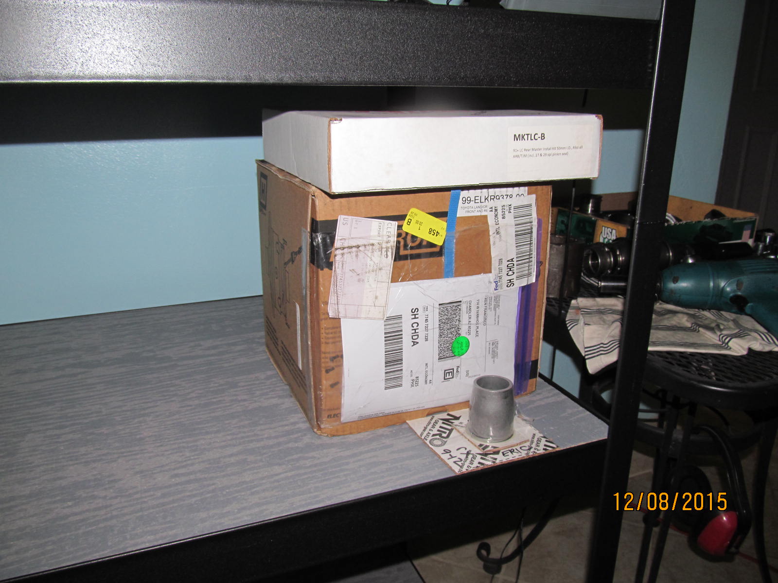
Also received the Harrop e-locker directly from Australia.
|
|
|
|
|
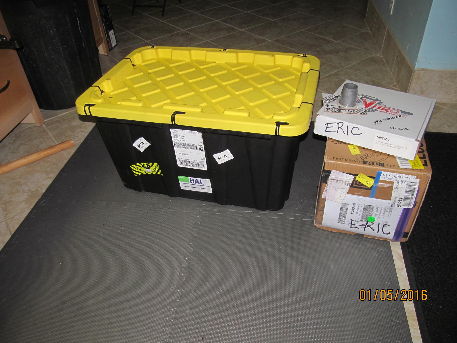
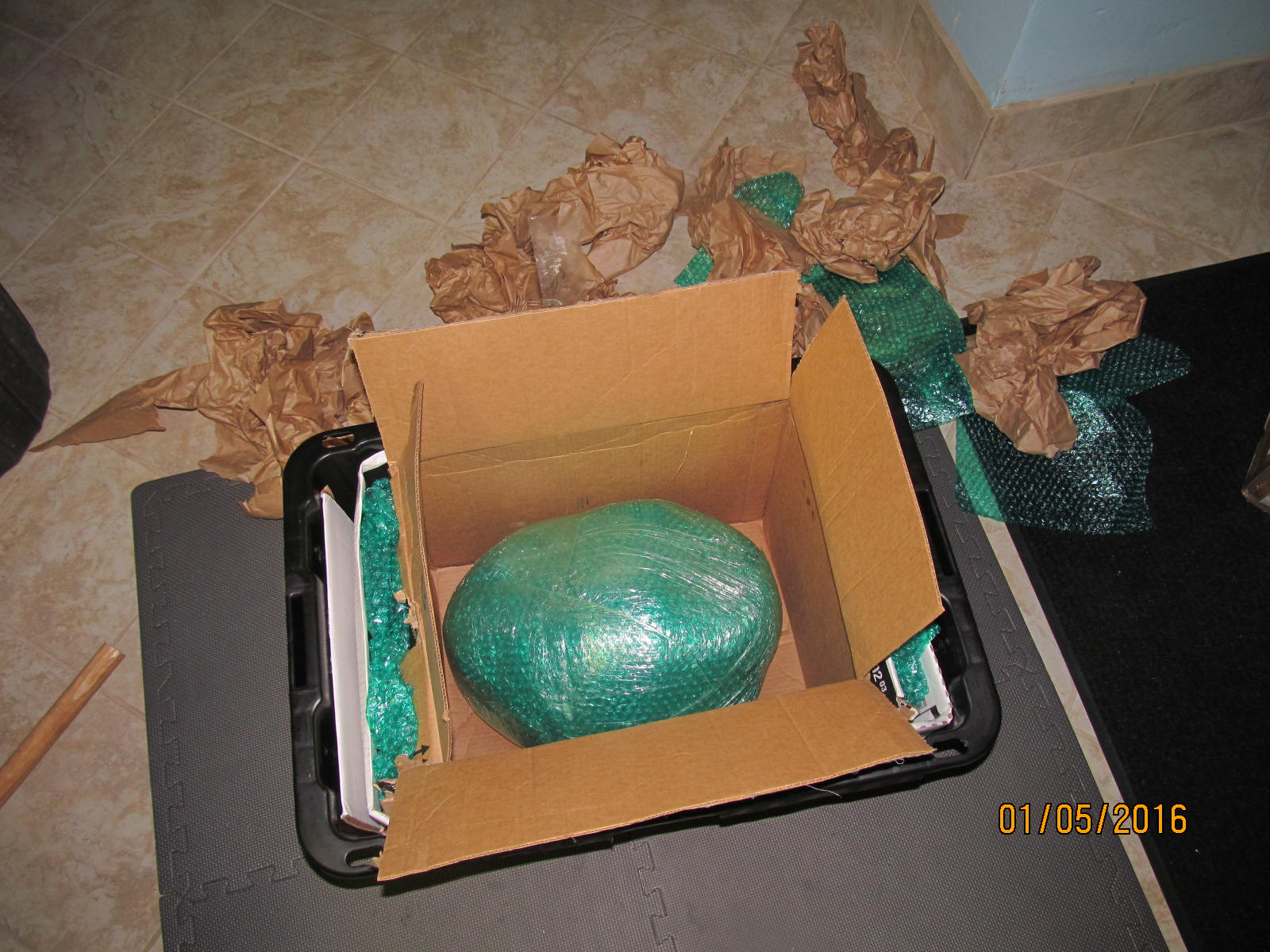
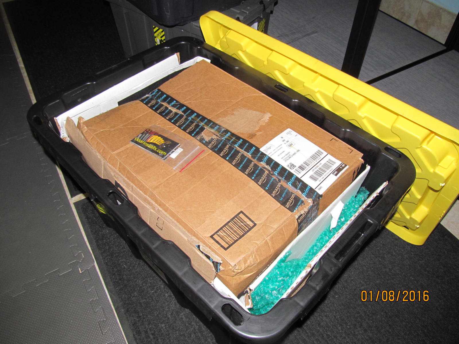
A tote arrived from Eric...
|
|
|
|
|
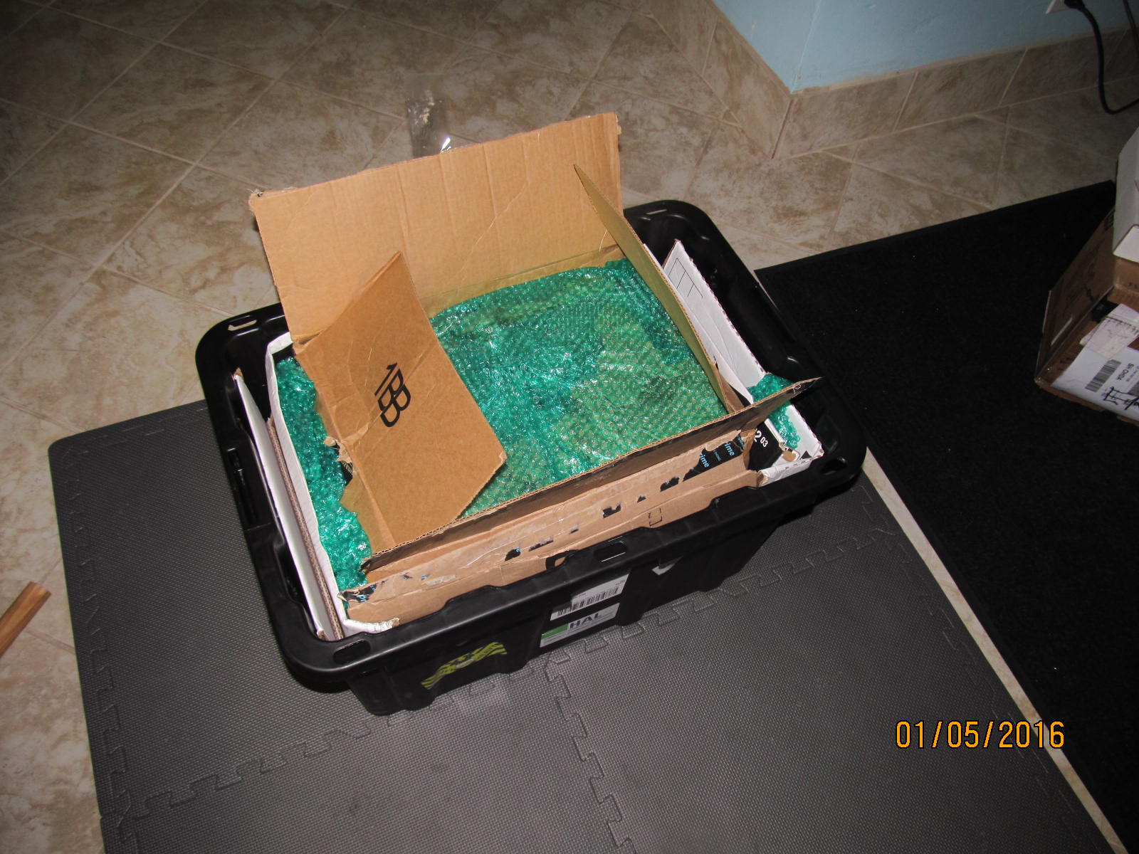
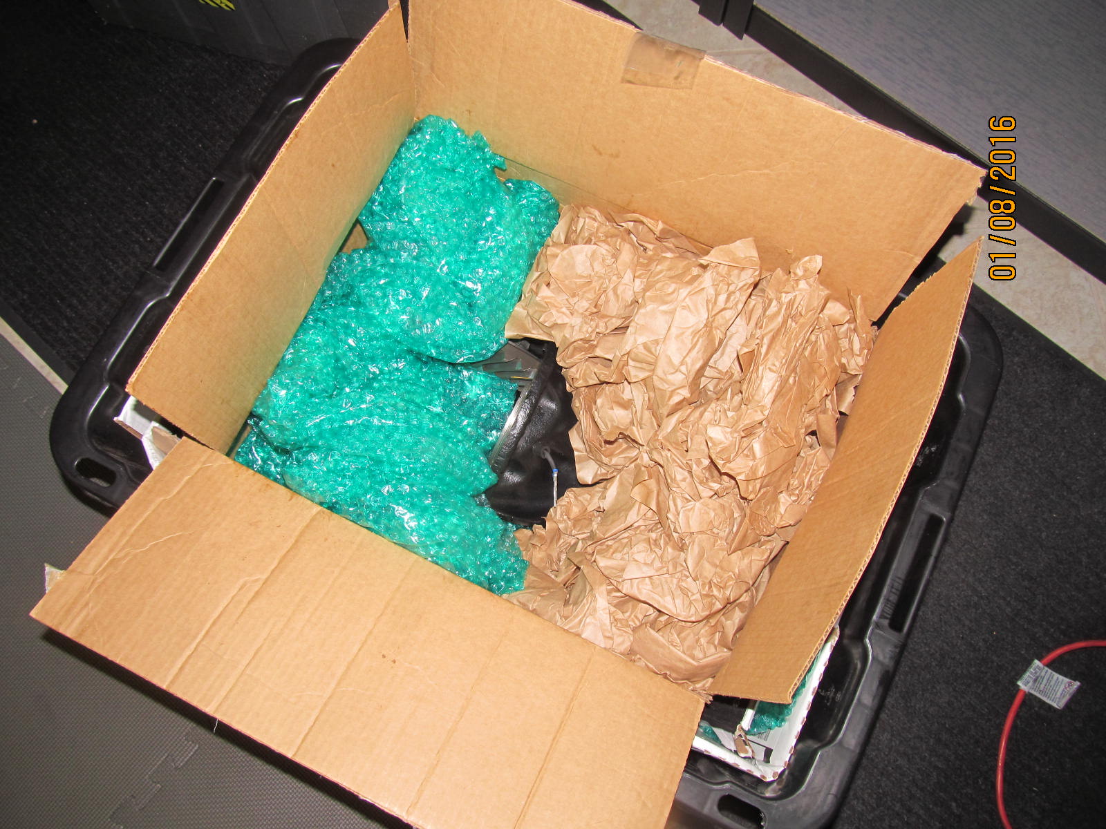
It is well cushioned.
|
|
|
|
|
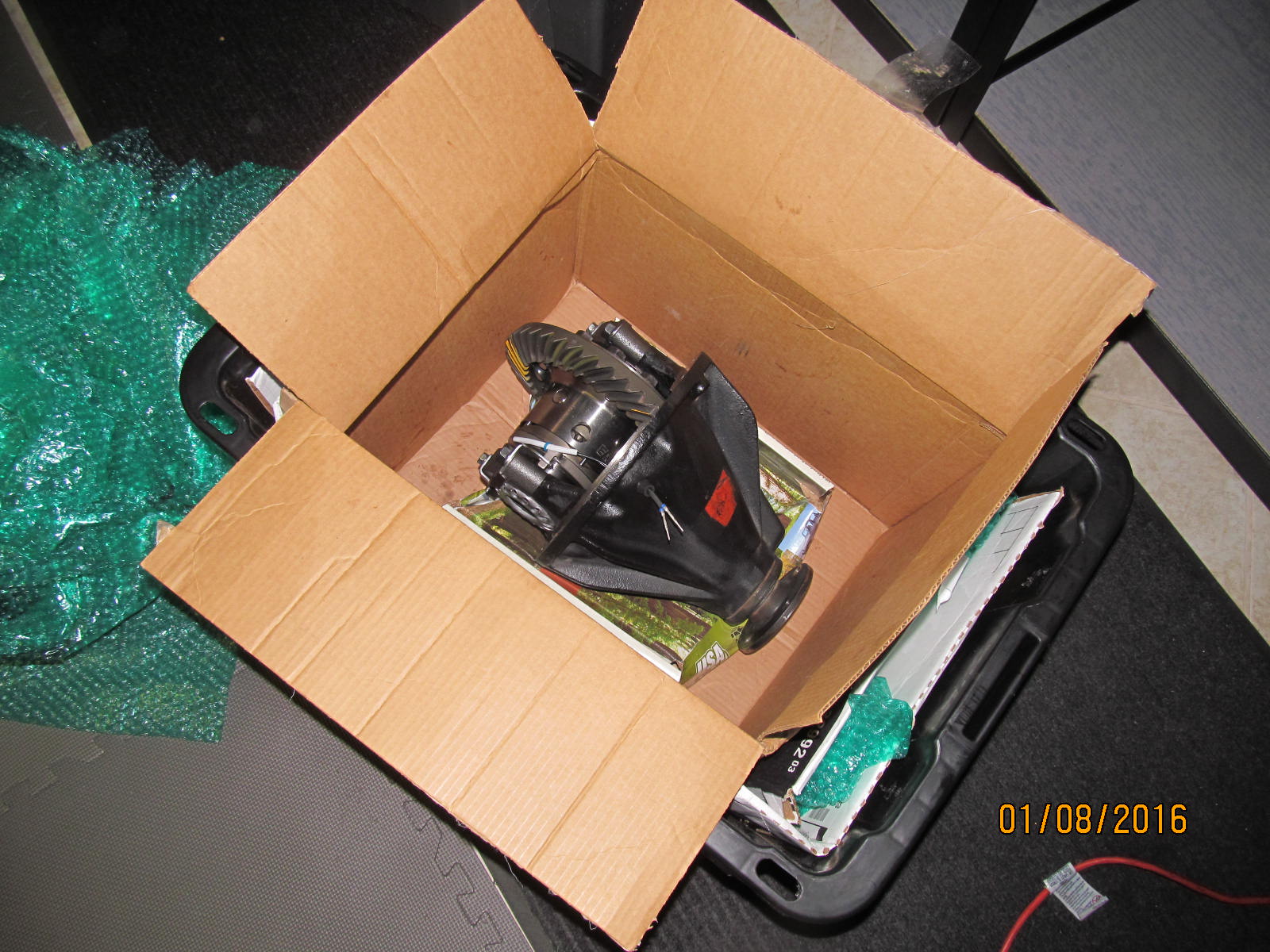
A well wrapped open 9.5" with bubble wrap and saran plastic wrap.
|
|
|
|
|
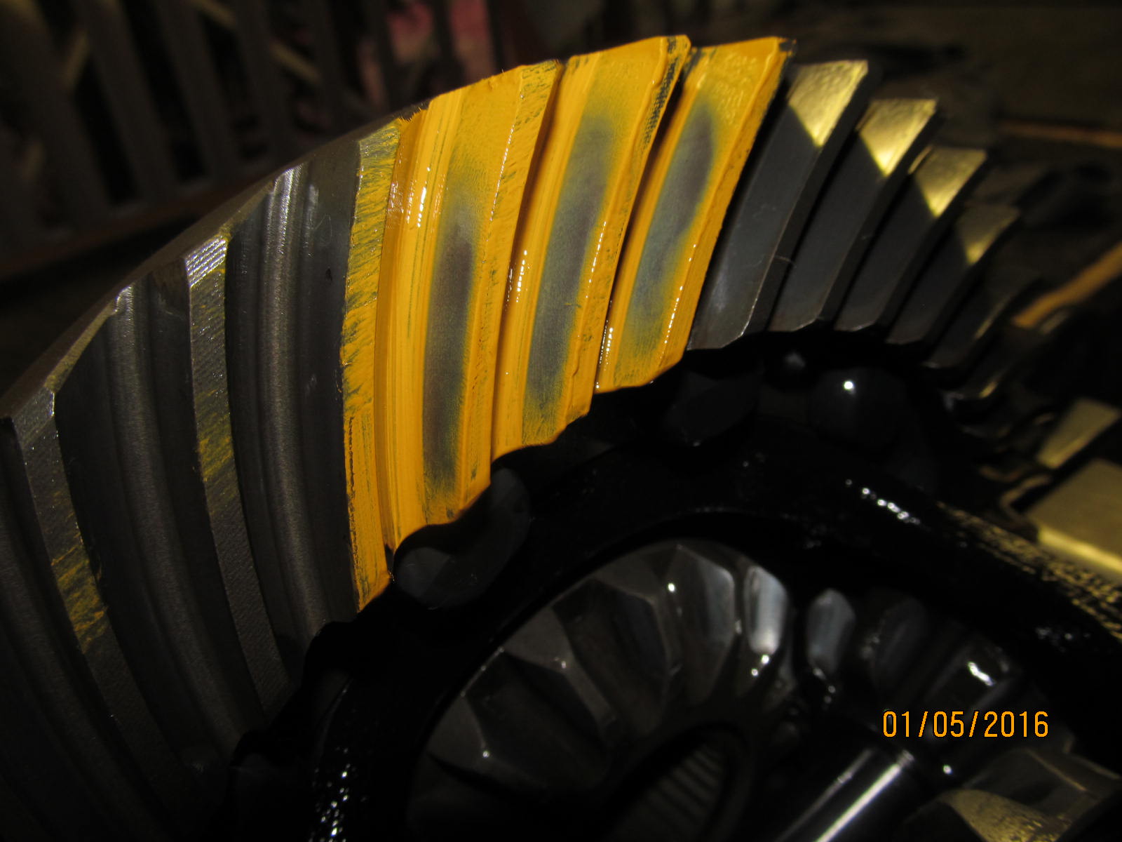
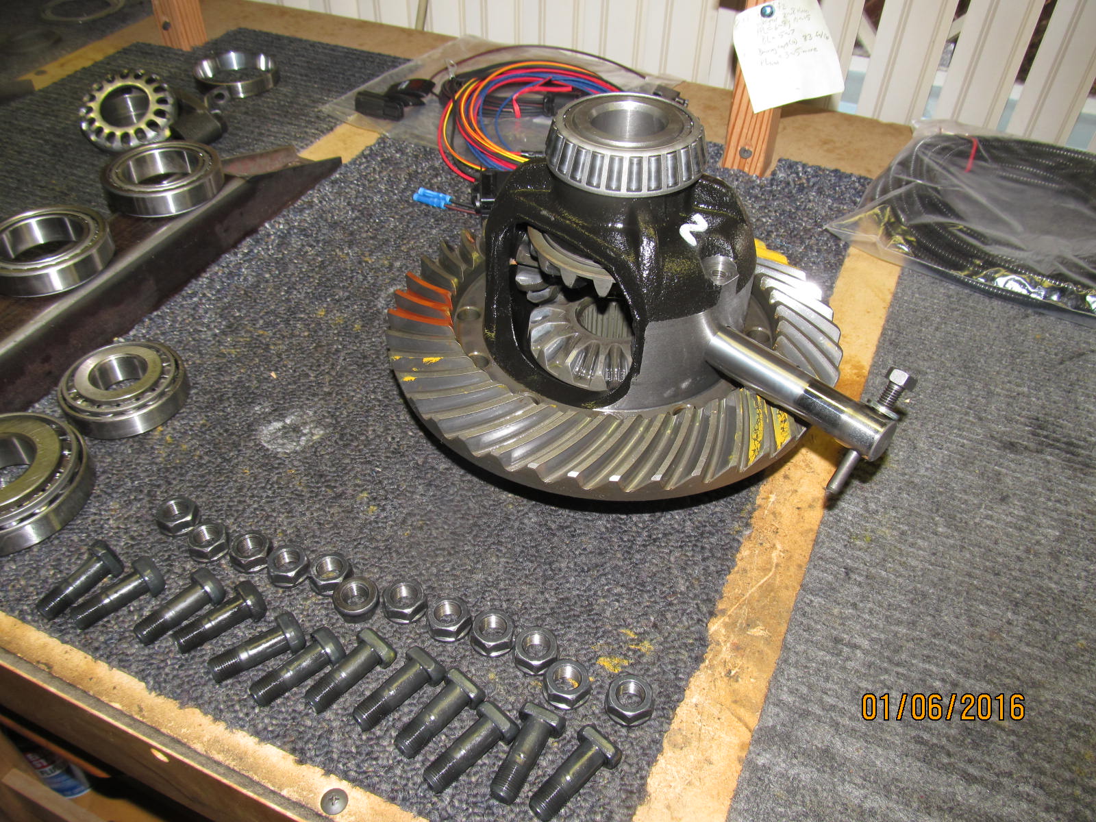
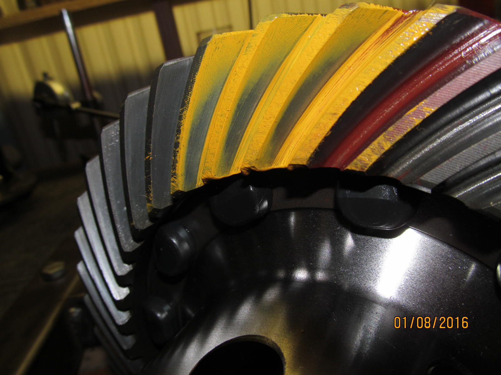
A quick pre-check of the painted pattern shows the gears are still good. Drive side.
|
|
|
|
|
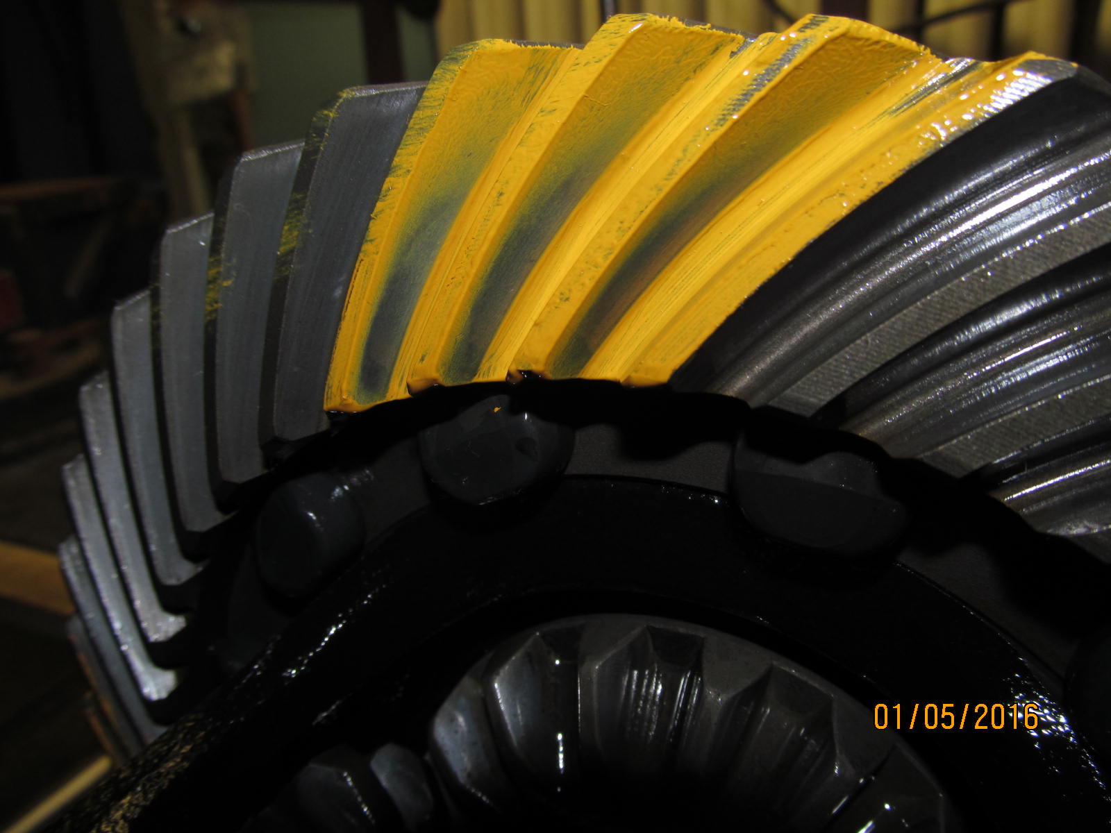
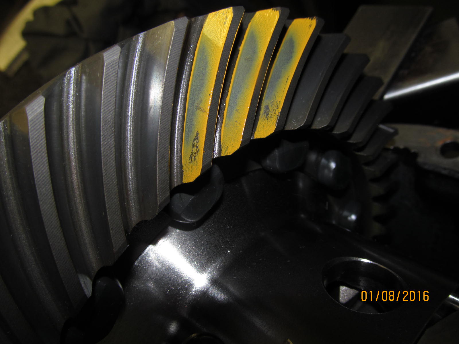
Coast side.
|
|
|
|
|
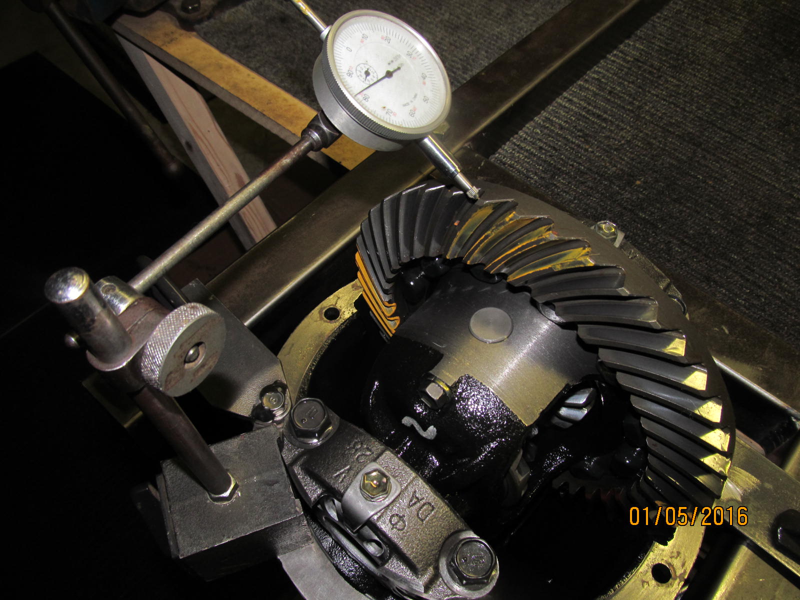
Original backlash was in the neighborhood of .005~.008"
|
|
|
|
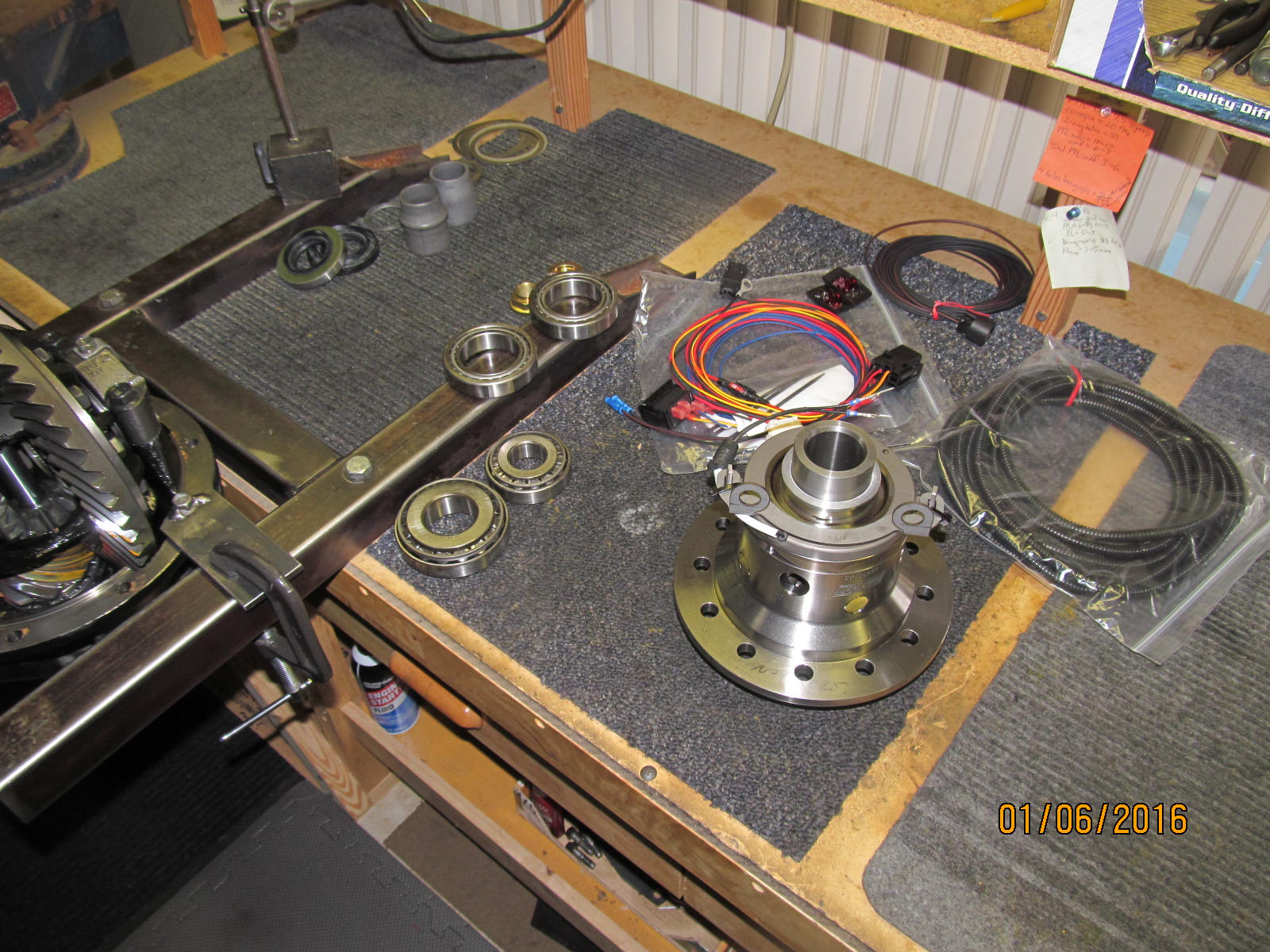
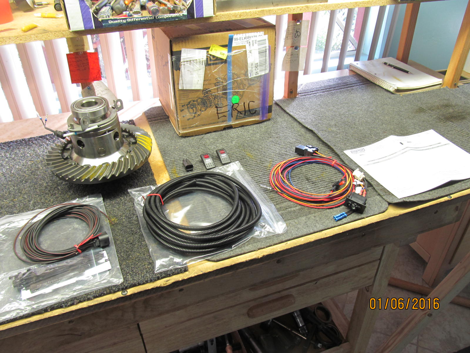
Everything is layed out and organized....don't get over-excited like I did because there were no paper
instructions supplied. More on that in a few pictures.
|
|
|
|
|
First task....removing the ring gear for re-use. Remove the 12 ring bolts/nuts and take the cross-pin out.
|
|
|
|
|
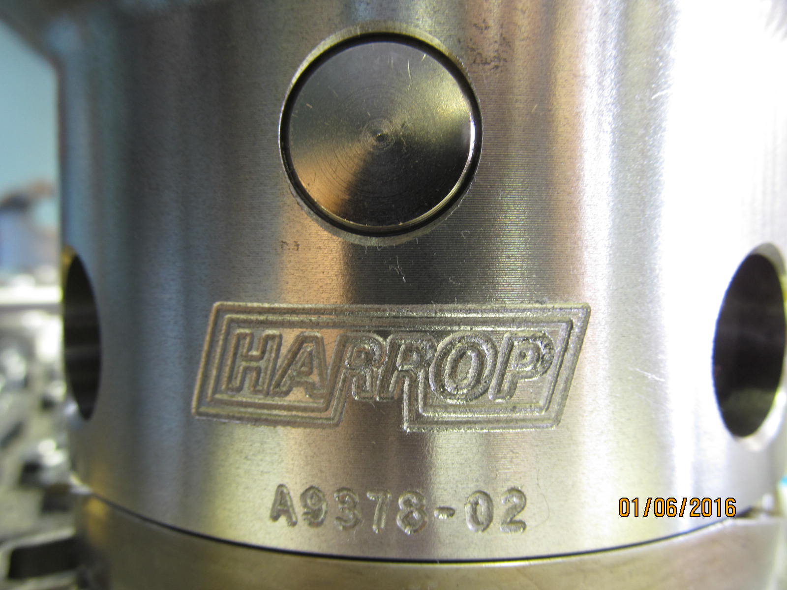
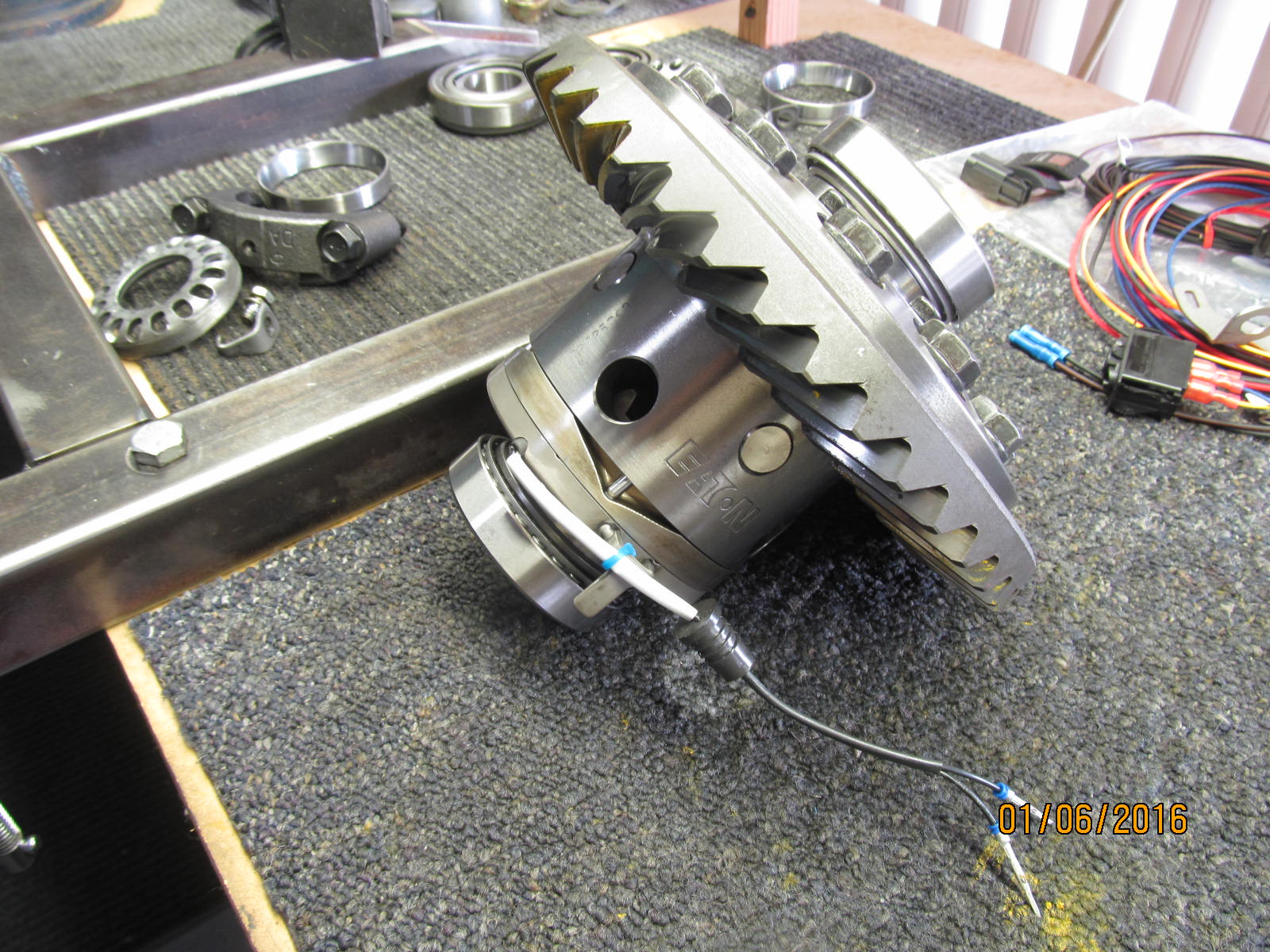
Engravings on the Harrop.
|
|
|
|
|
Nicely machined.
|
|
|
|
|
..............
|
|
|
|
|
The bracket that was included with the Harrop shown located in place over the locker tabs.
|
|
|
|
|
On to business, the original ring is bolted in place with 81 ft/lb on the 12 ring bolts/nuts.
|
|
|
|
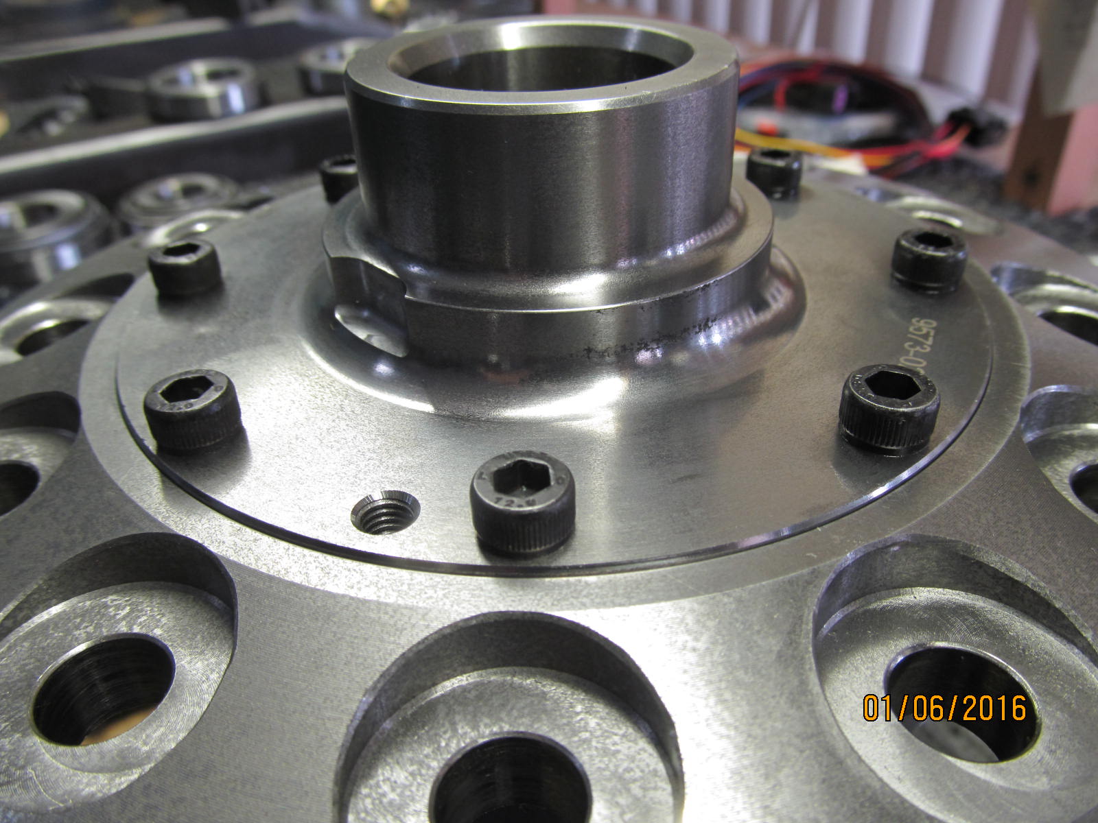
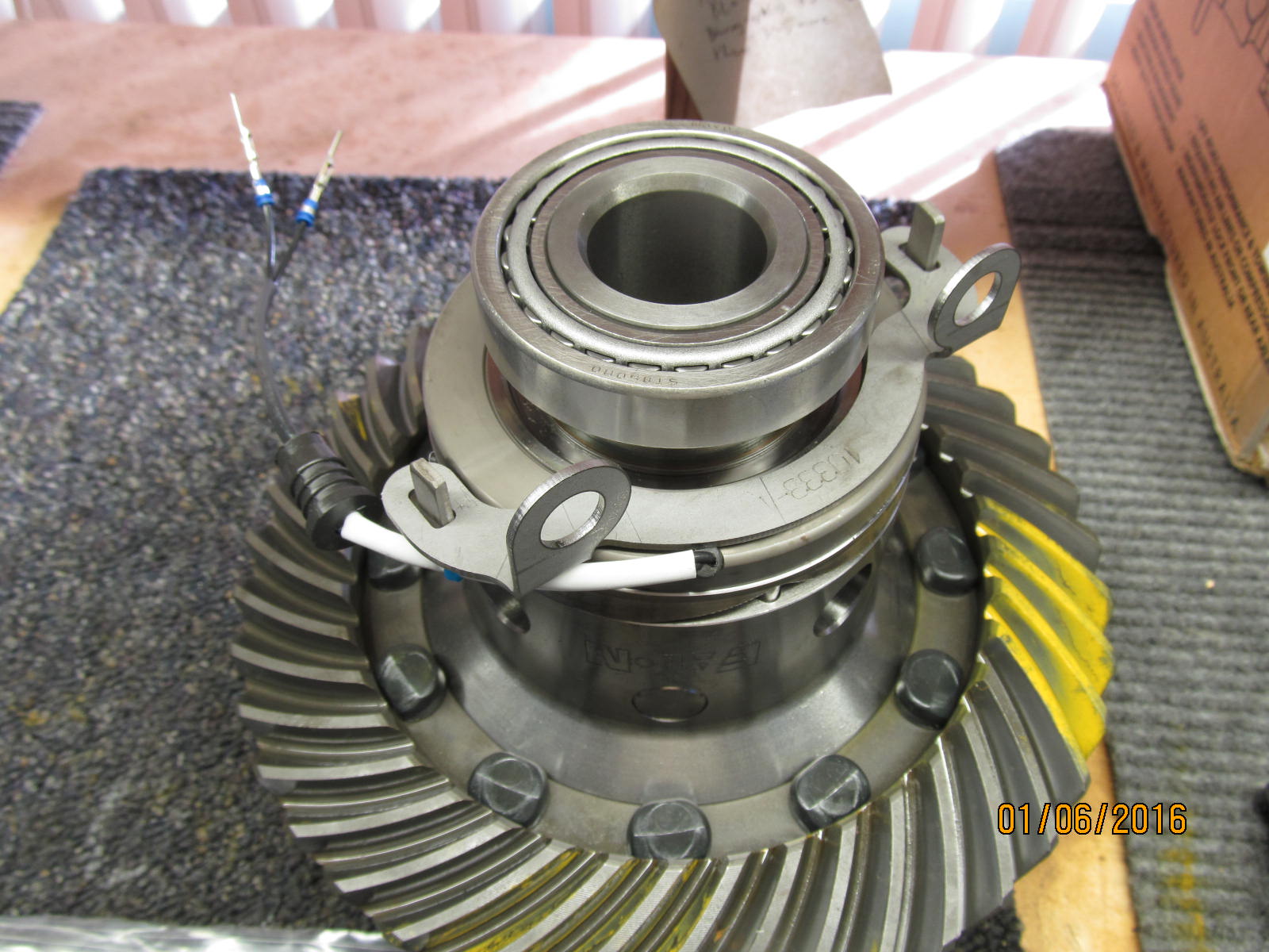
New bearings from the master kit are pressed on the locker journals.
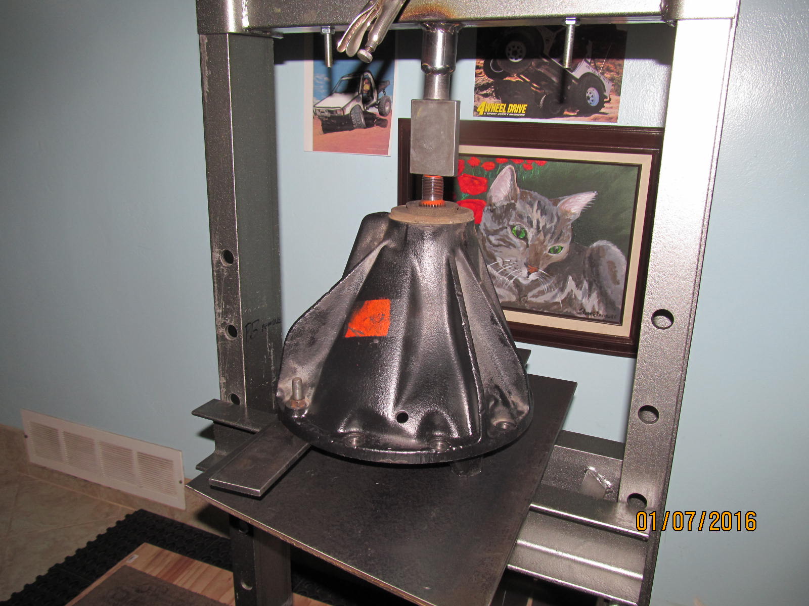
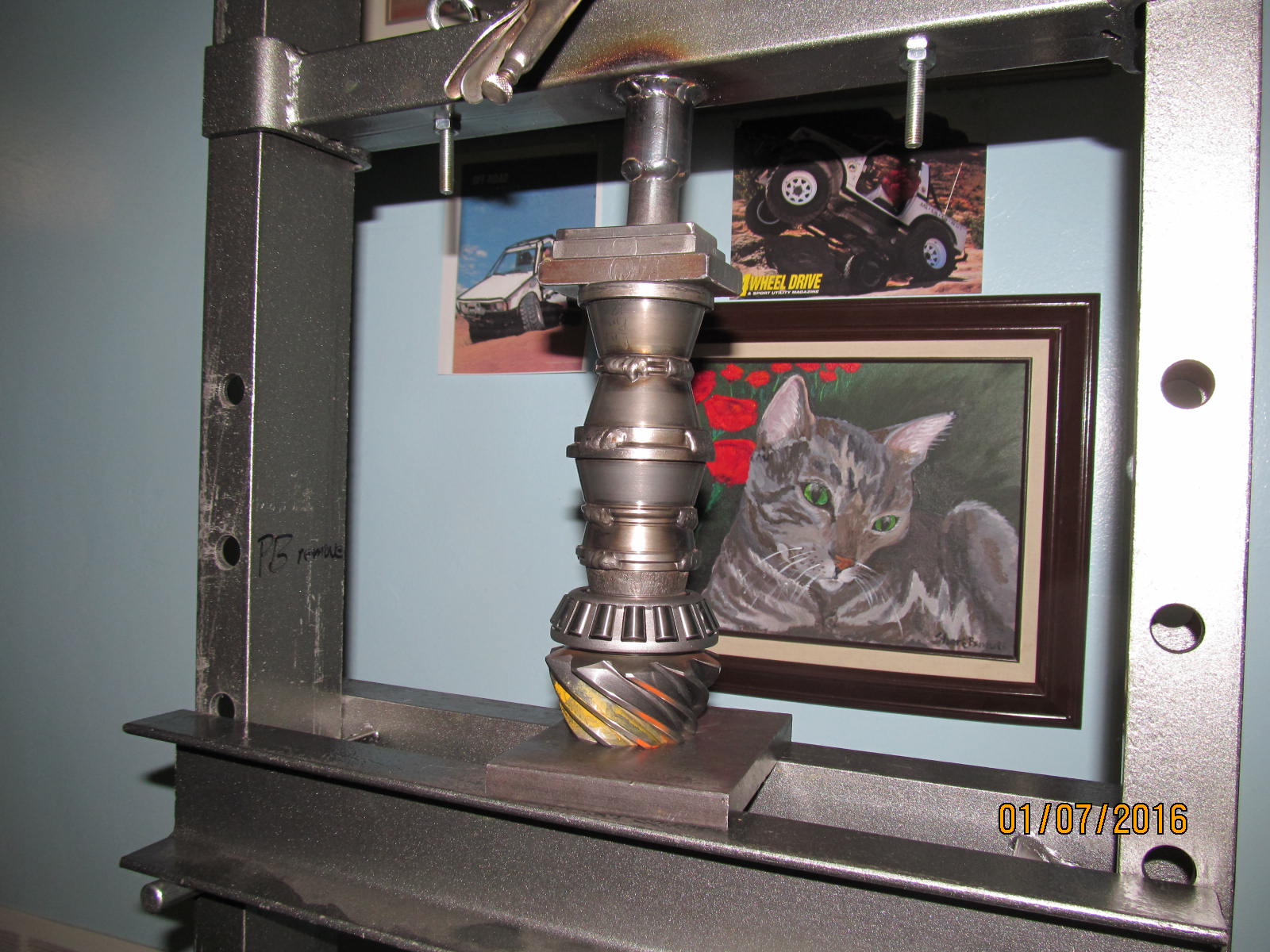
My younger sister painted that kitty portrait herself.
|
|
|
|
|
Ring and carrier bearings are on.....nothing more to do with this piece of the puzzle.
|
|
|
|
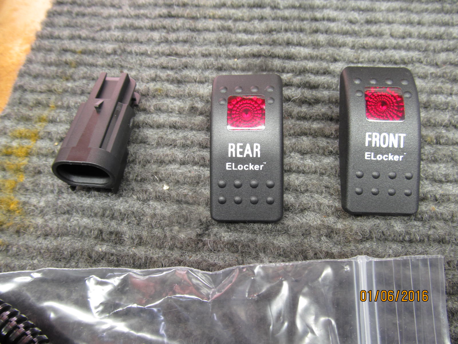
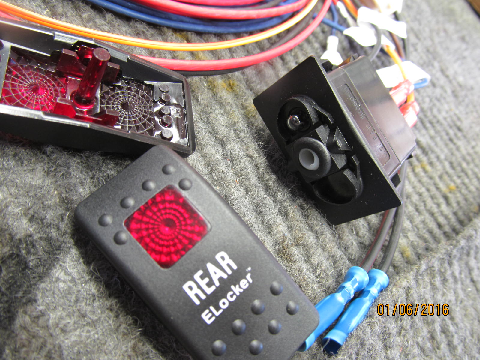
The locker stuff is layed out....at the time, I was thinking how the heck could they forget the instructions.
Actually, they included an extra "front locker" switch toggle cover as shown....no front locker
planned in this rig yet.
|
|
|
|
|
.............
|
|
|
|
That's where the instructions are.....ok.
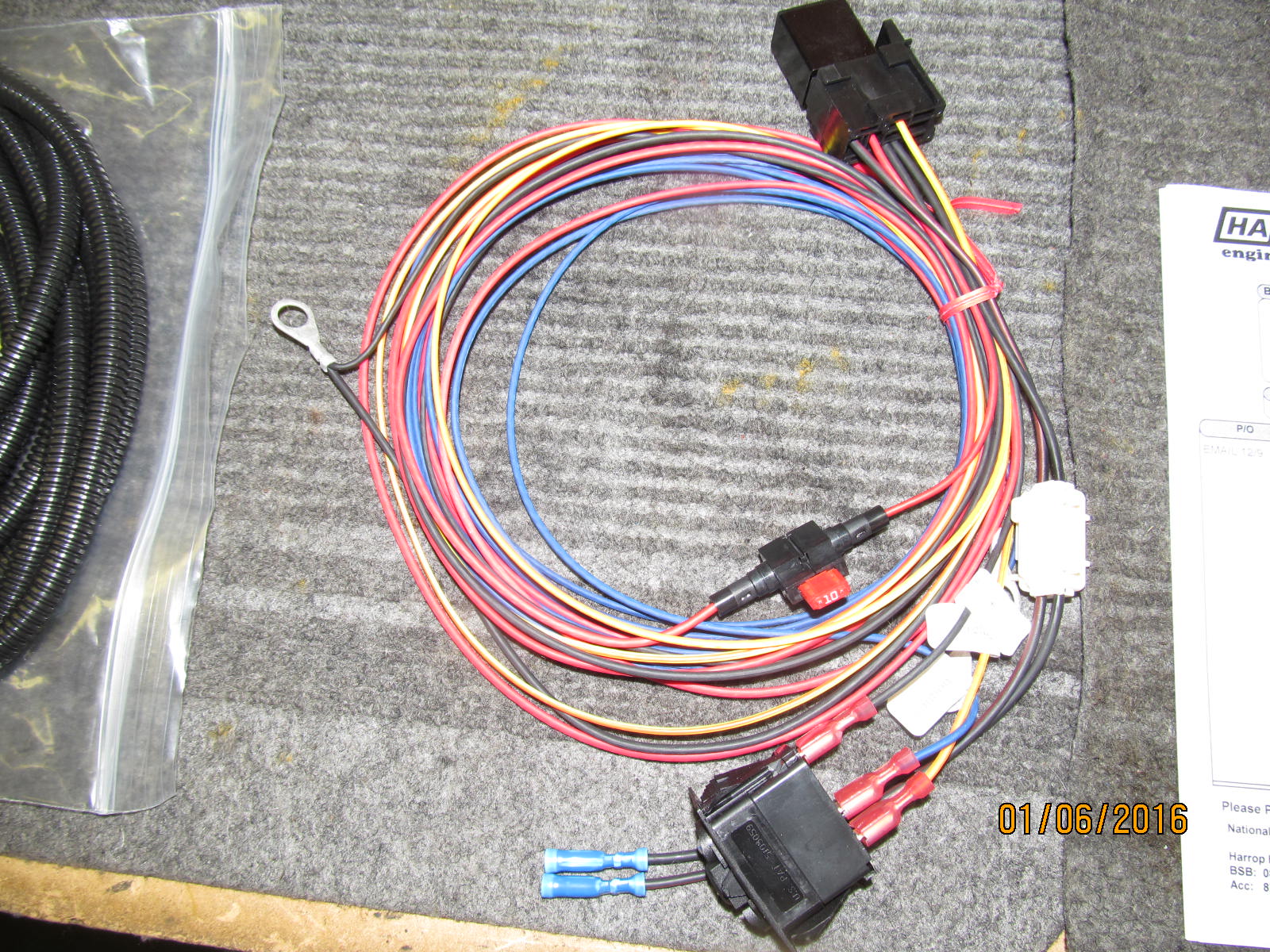
This is the harness piece that gets spliced into the 2 e-locker wires and routes up to the dash.
|
|
|
|
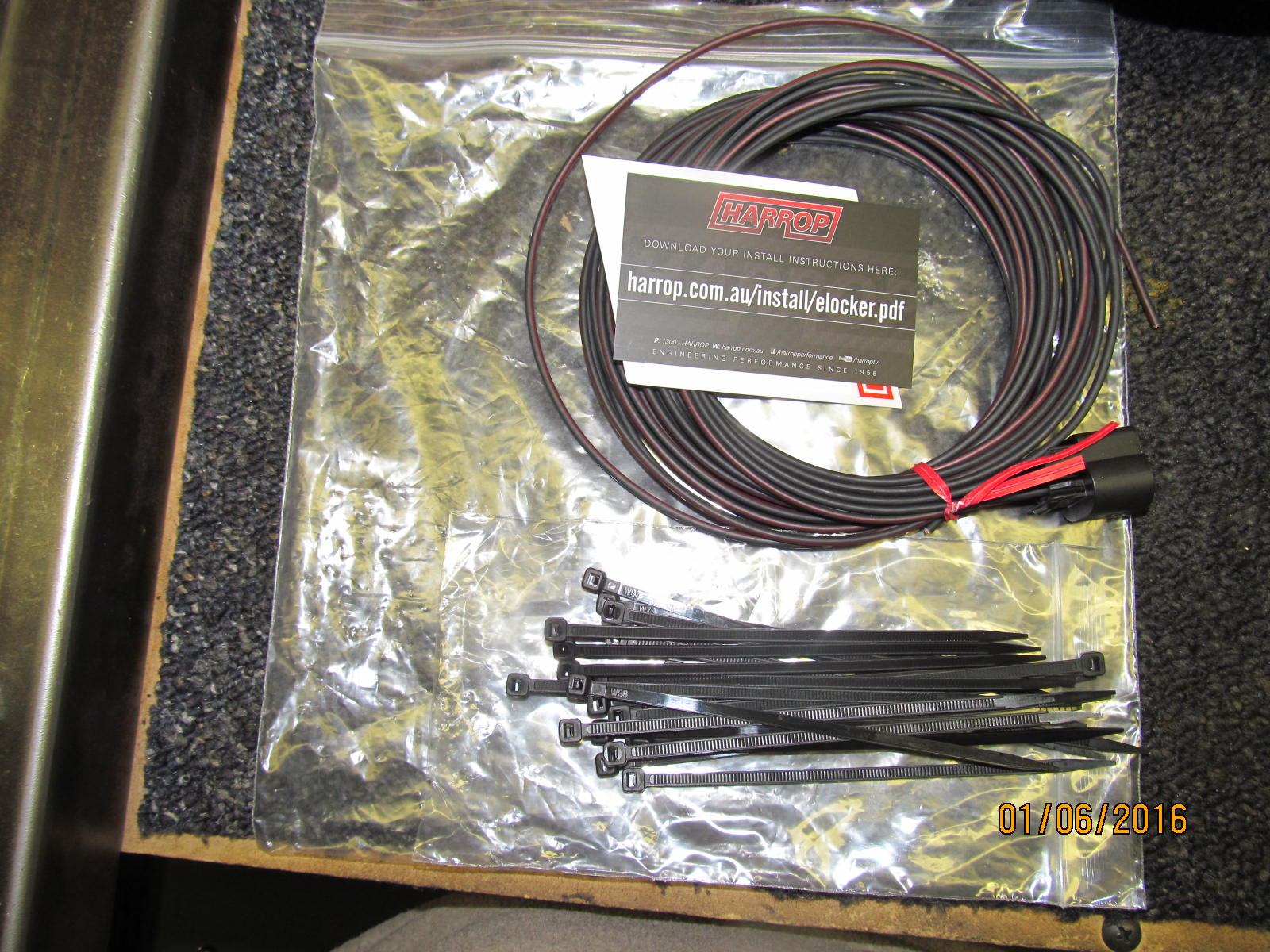
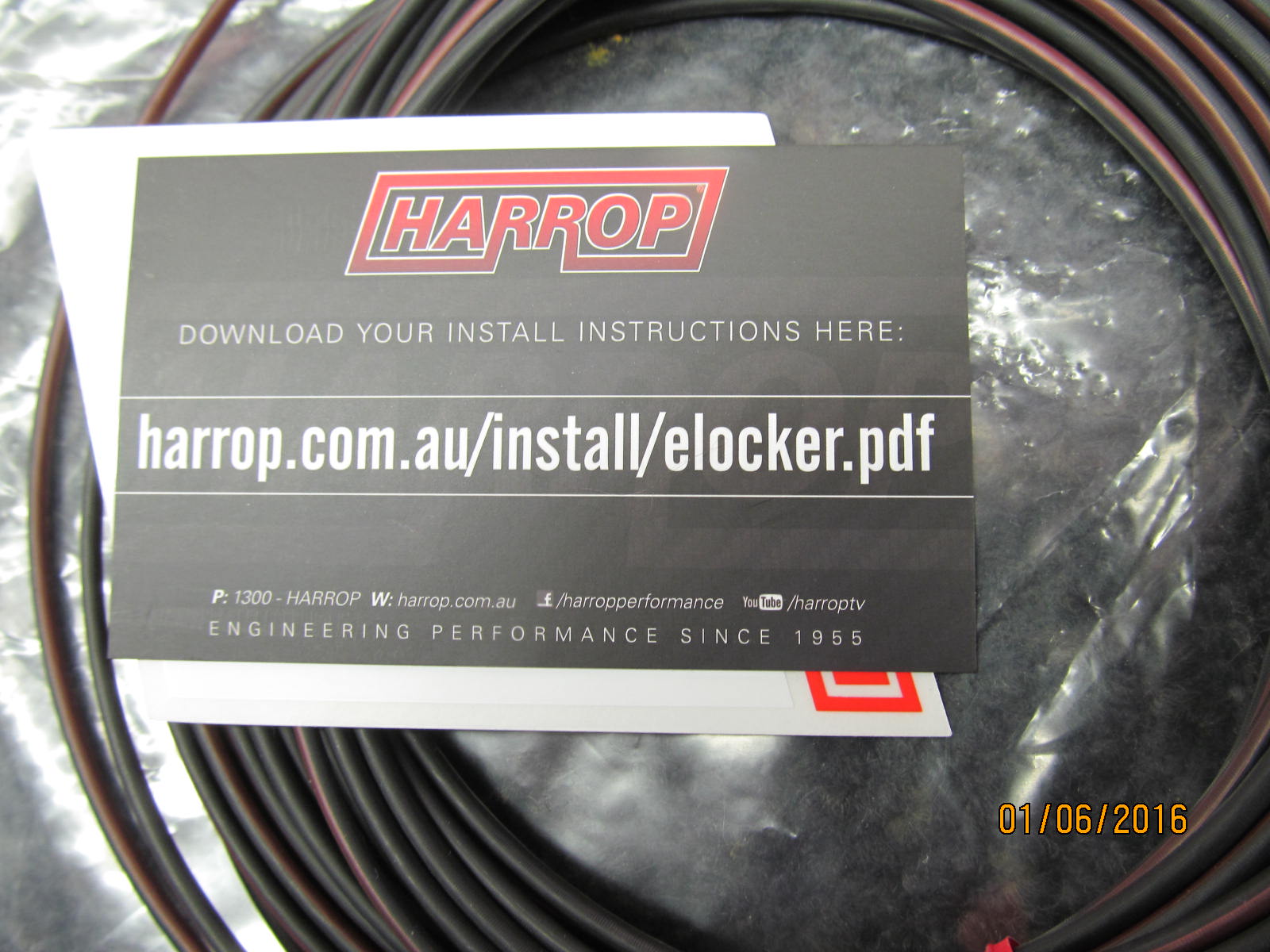
Instructions from their website.... harrop.com.au/install/elocker.pdf
Also available from my server Harrop Instructions
|
|
|
|
|
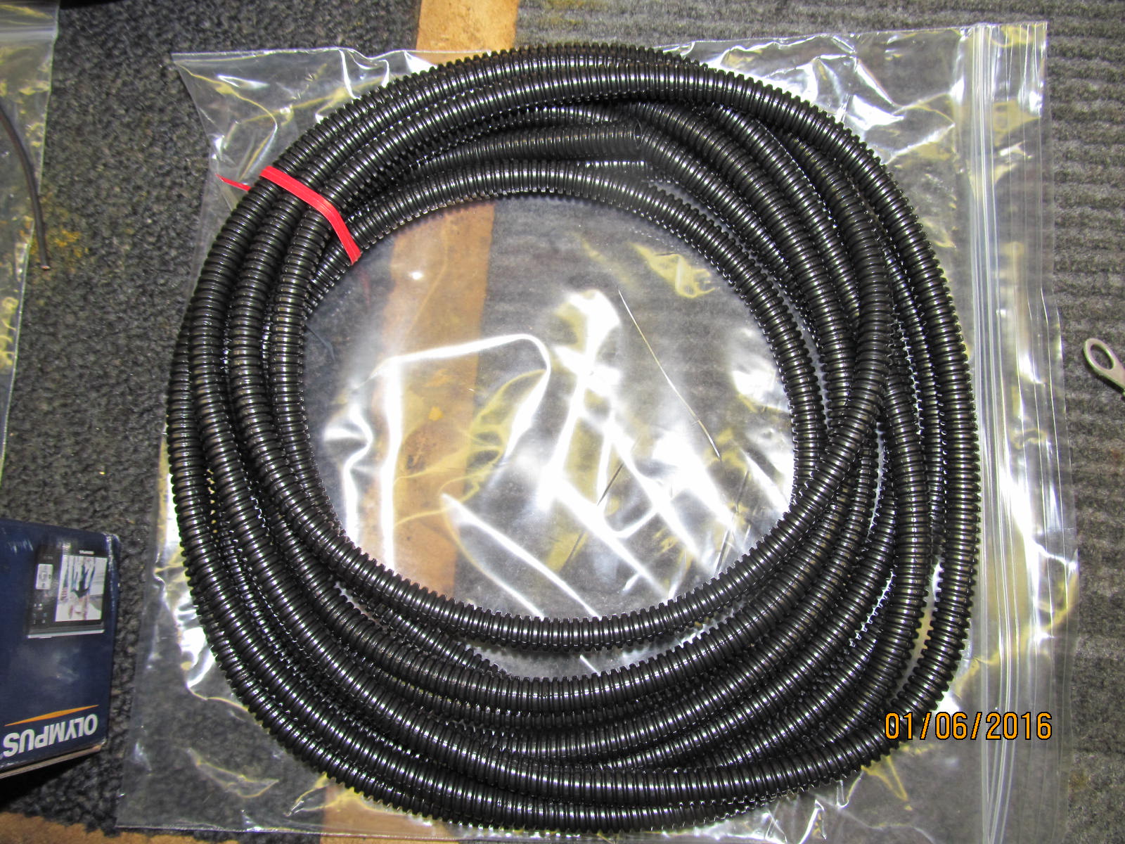
Conduit that was supplied.
|
|
|
|
|
The other part of the wiring harness.
|
|
|
|
|
..............
|
|
|
|
|
....................
|
|
|
|
|
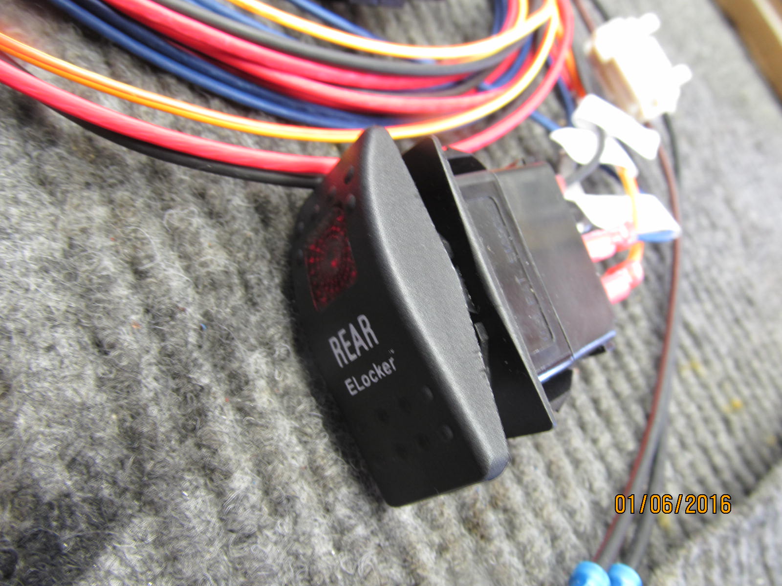
Rear cover snaps in place nicely and makes for a good quality toggle switch.
|
|
|
|
|
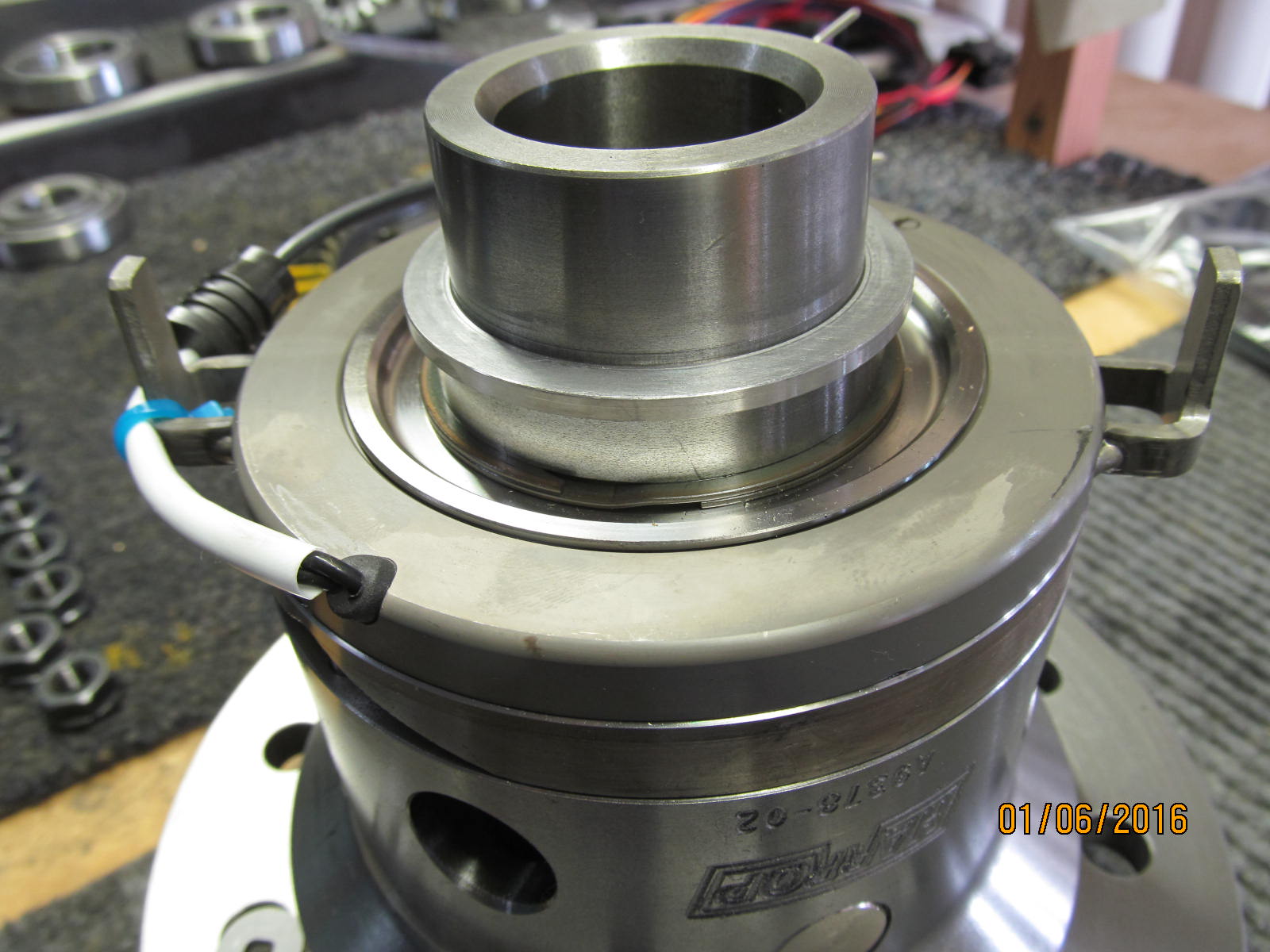
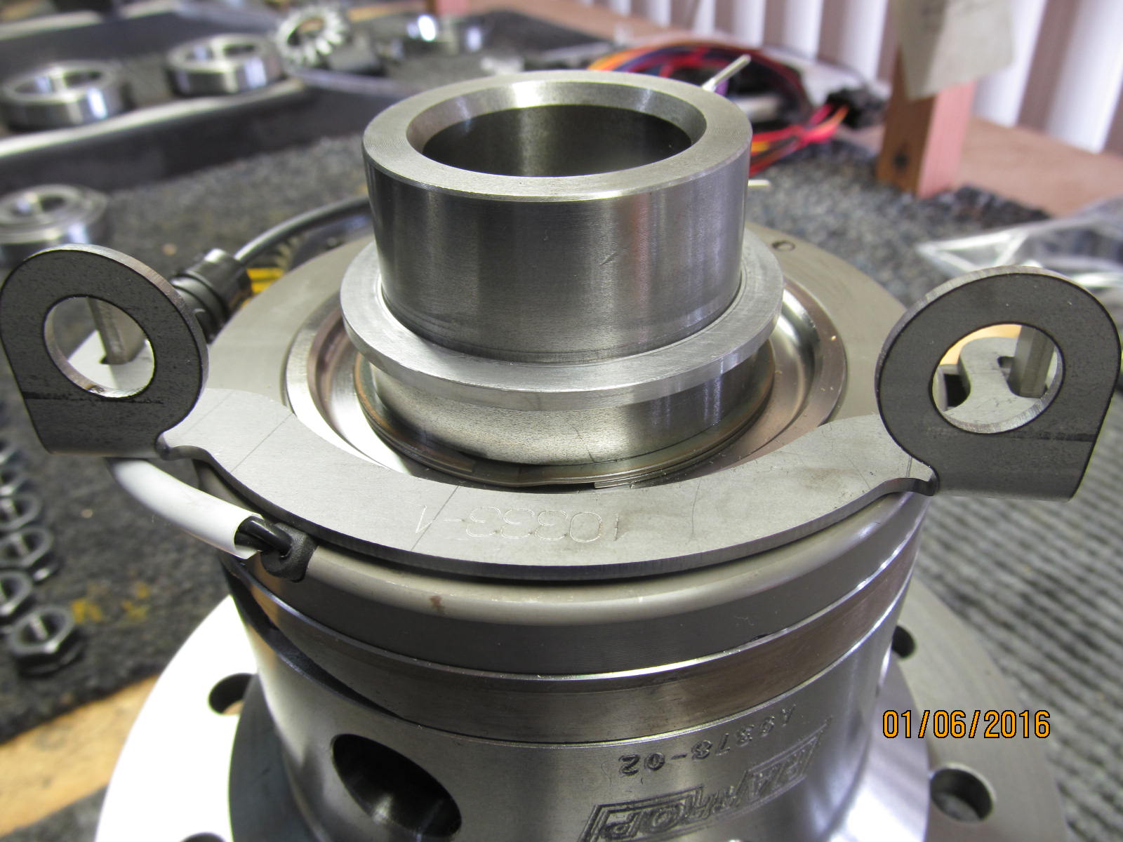
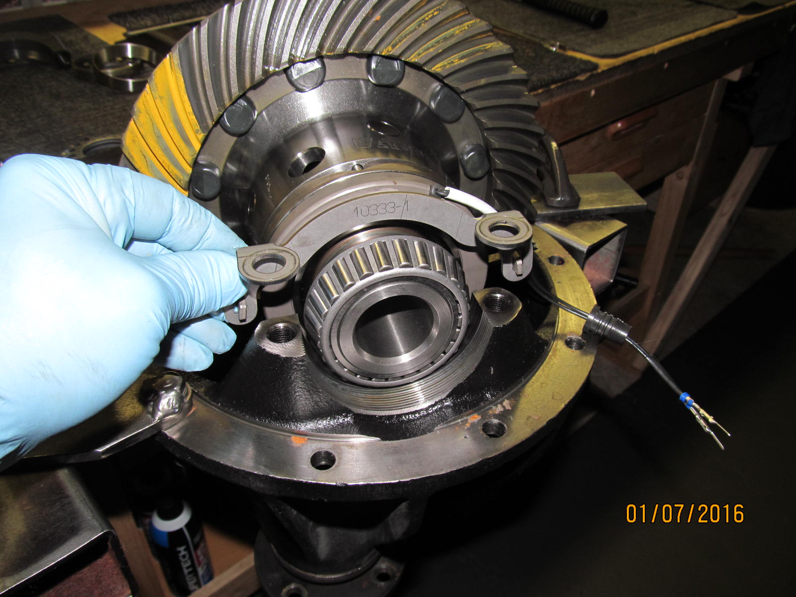
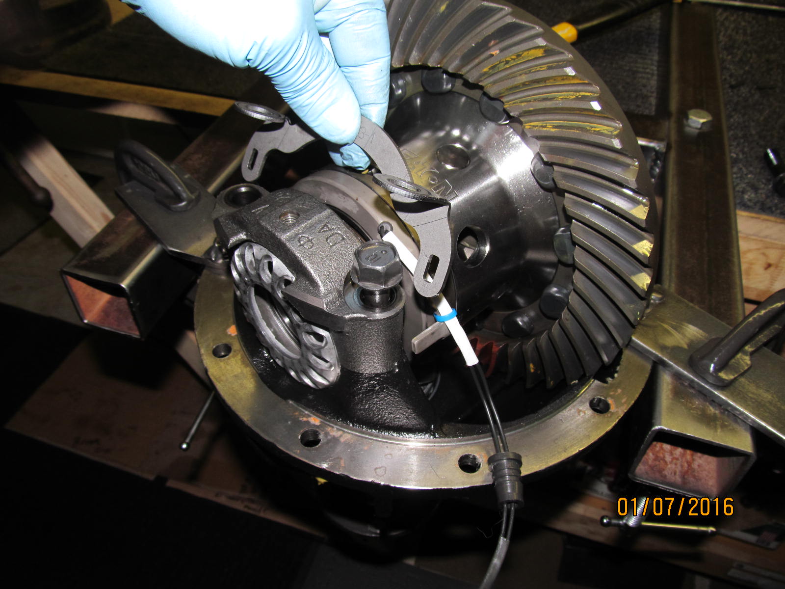
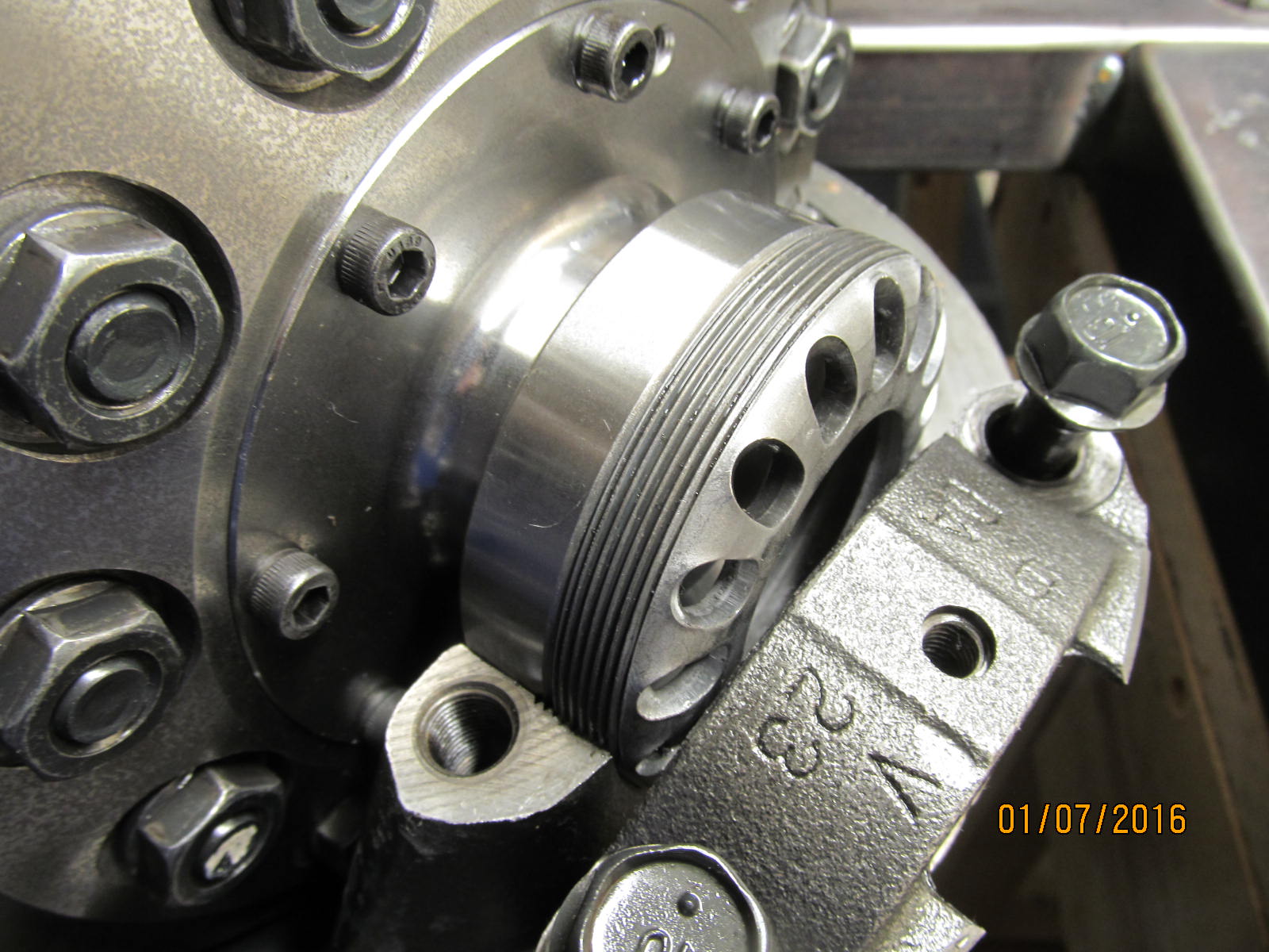
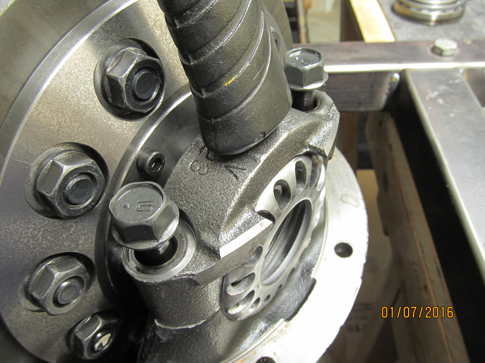
This supplied bracket goes here and slides into the 2 tabs from the Harrop.
|
|
|
|
|
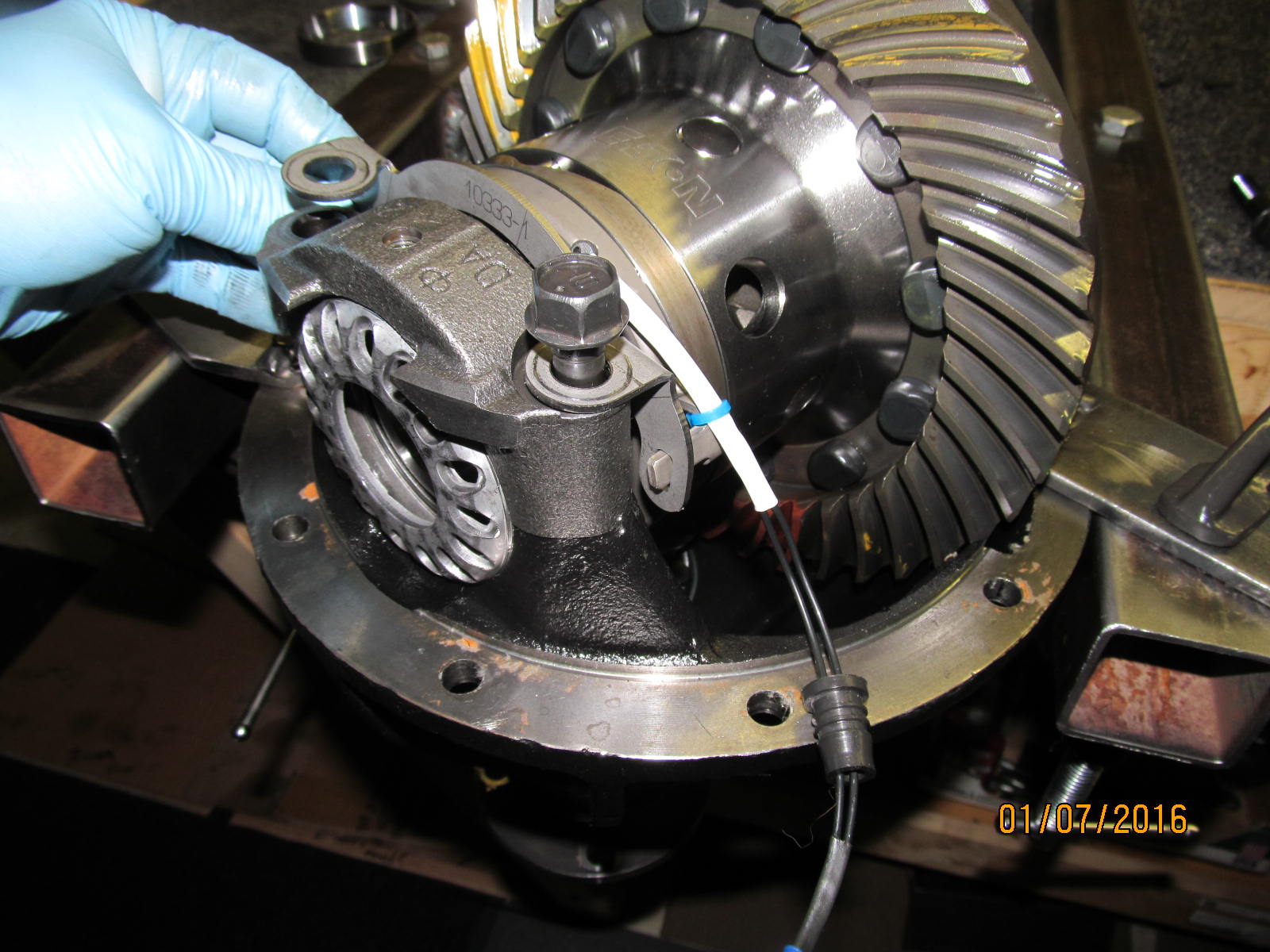
Cap goes in loosely in place....
|
|
|
|
|
A little bit of jiggling helps the bracket go smoothly in place.....
|
|
|
|
|
....but if I can do then anybody can do it.
|
|
|
|
|
That one stubborn tab will drop in place if you lift the Harrop case up for a moment.
|
|
|
|
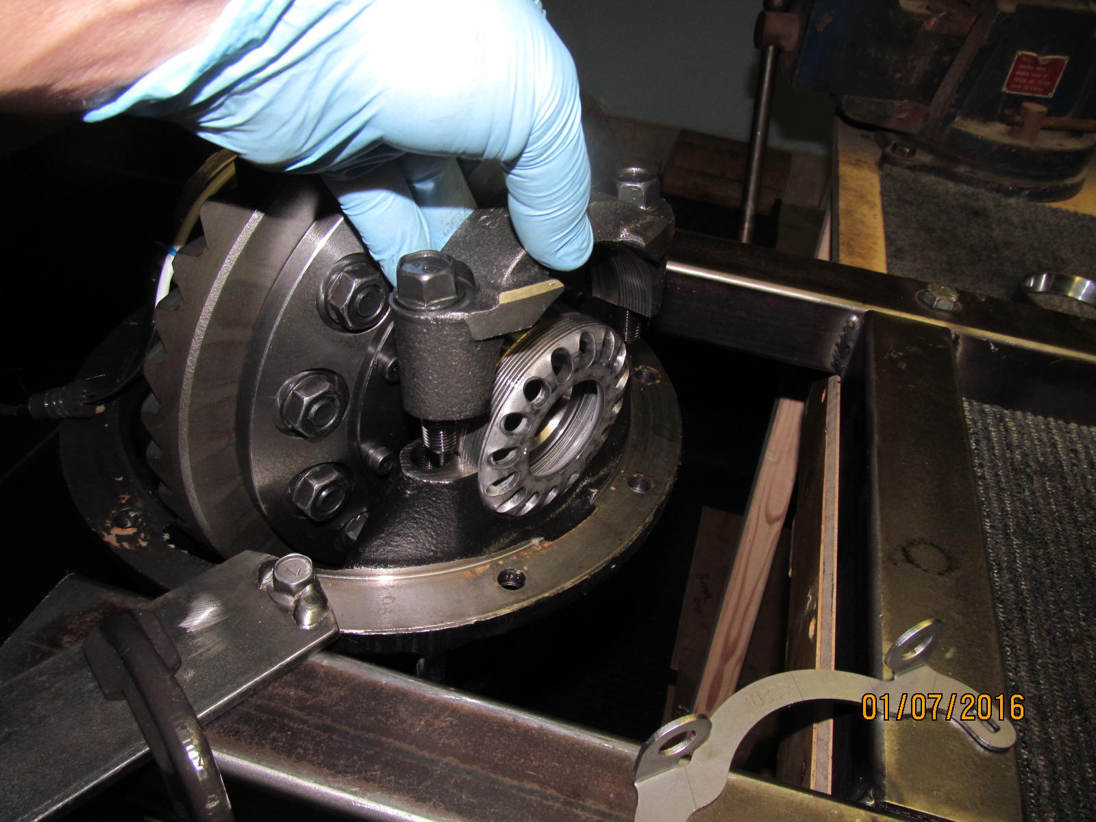
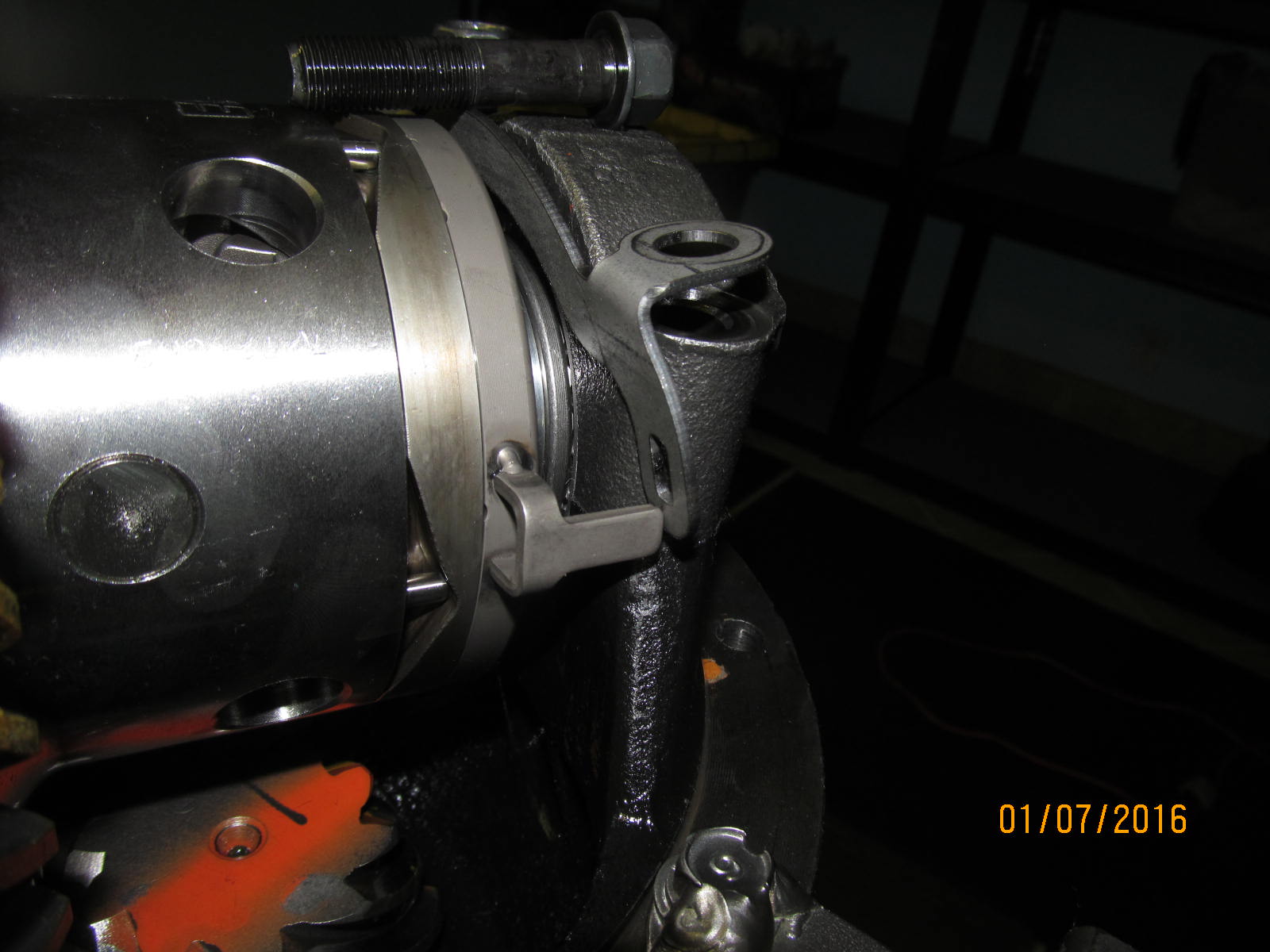
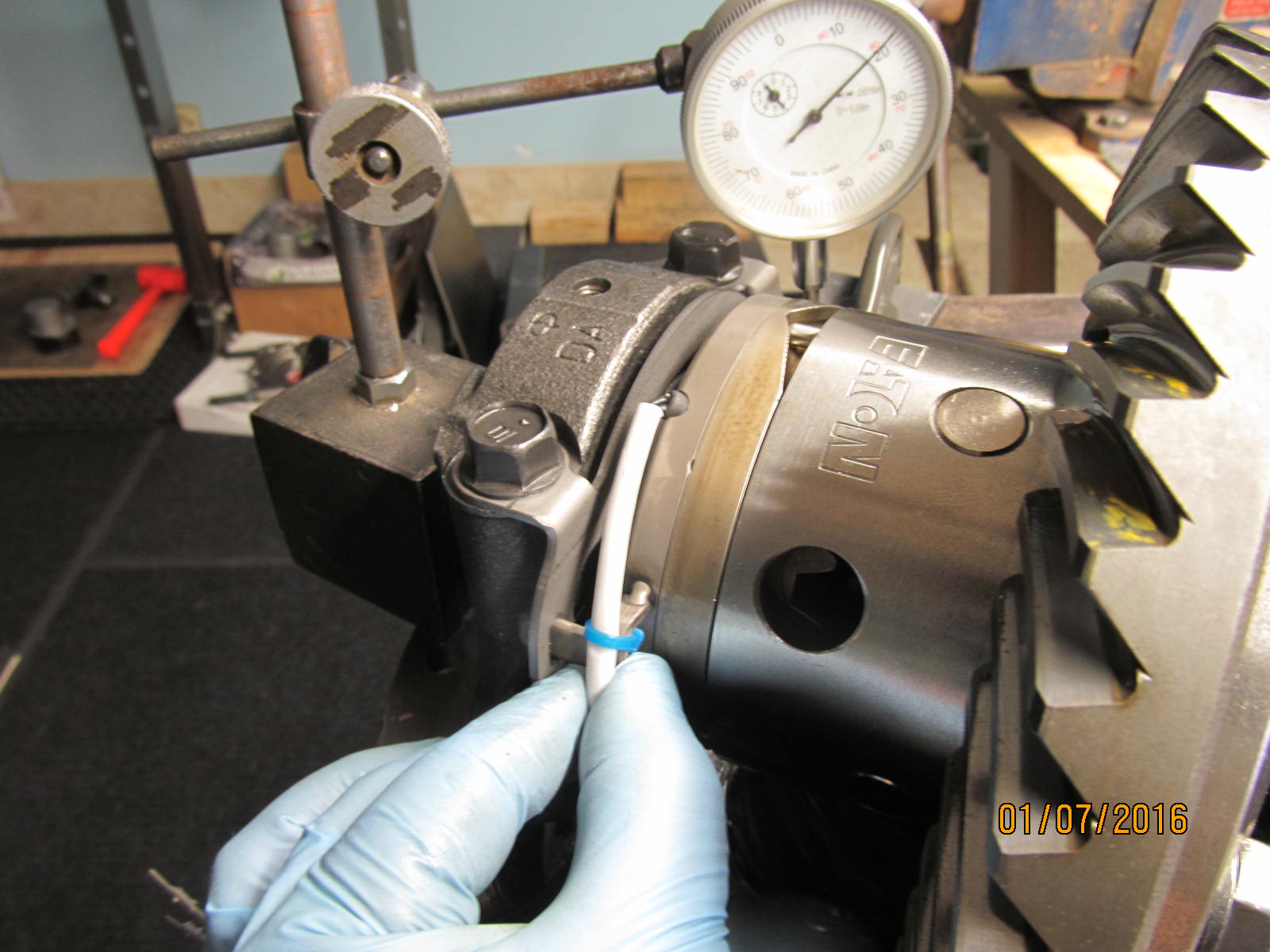
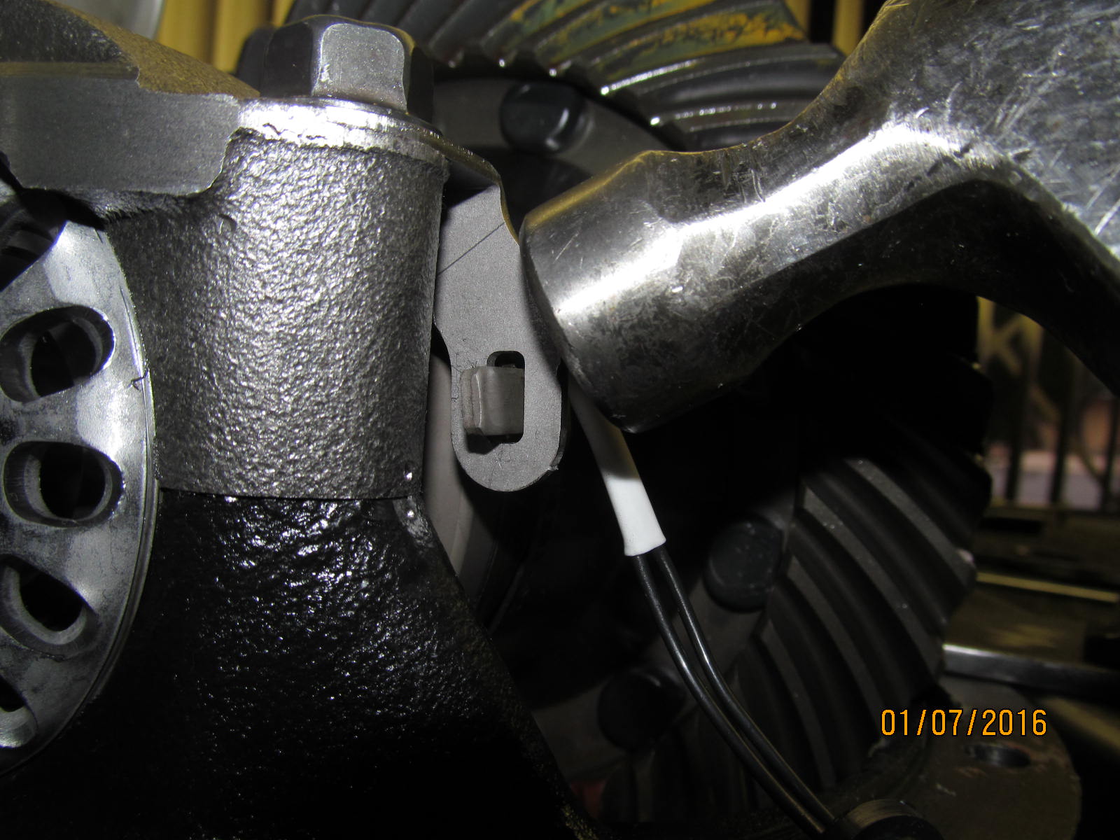
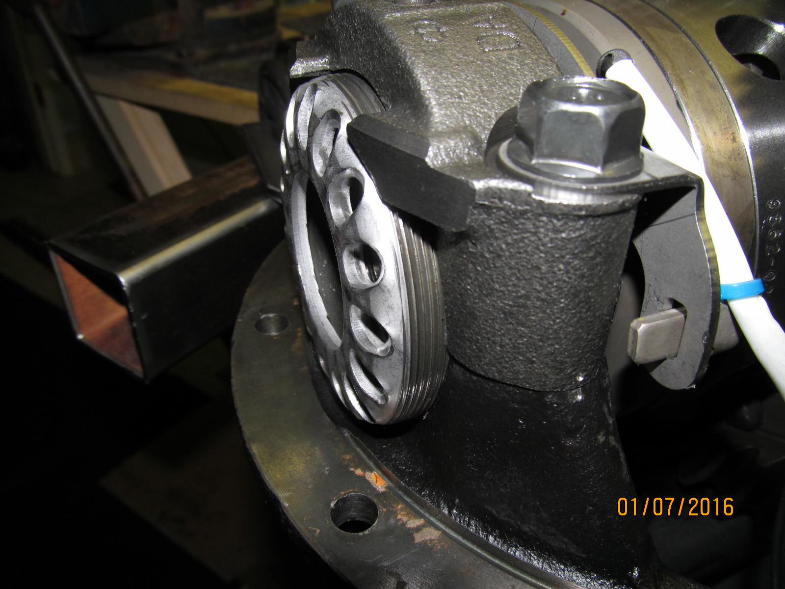
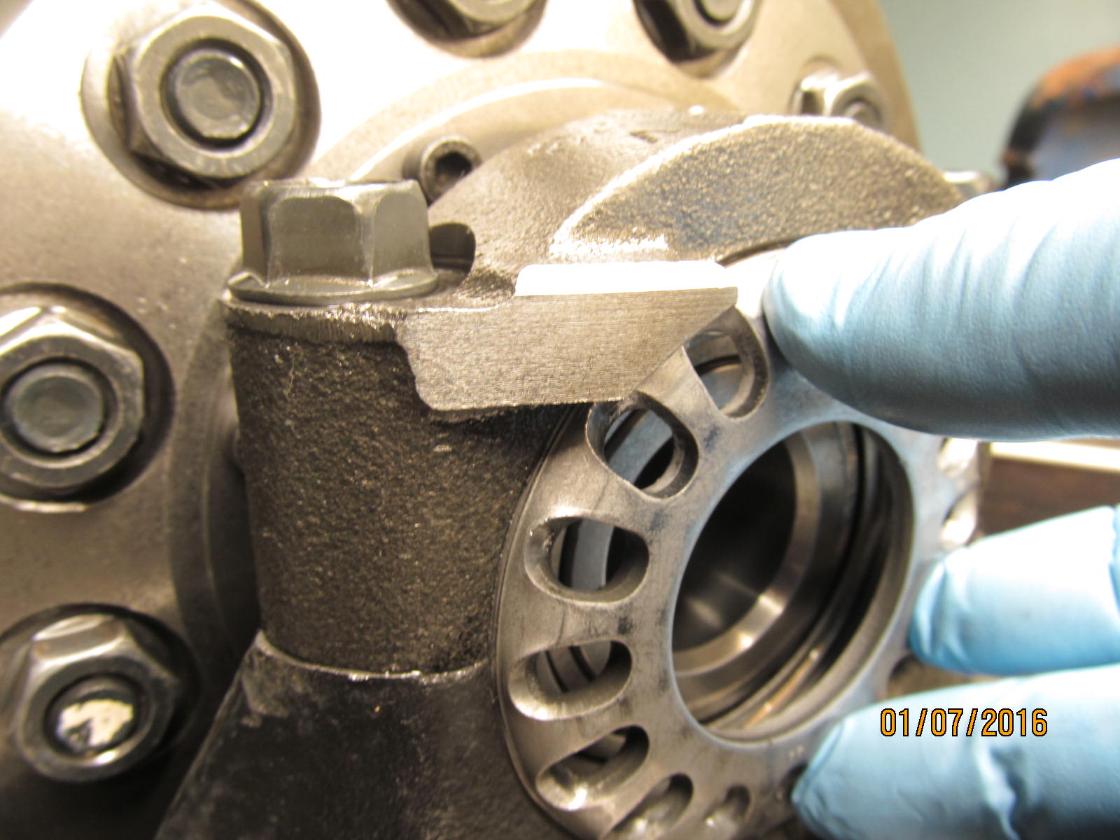
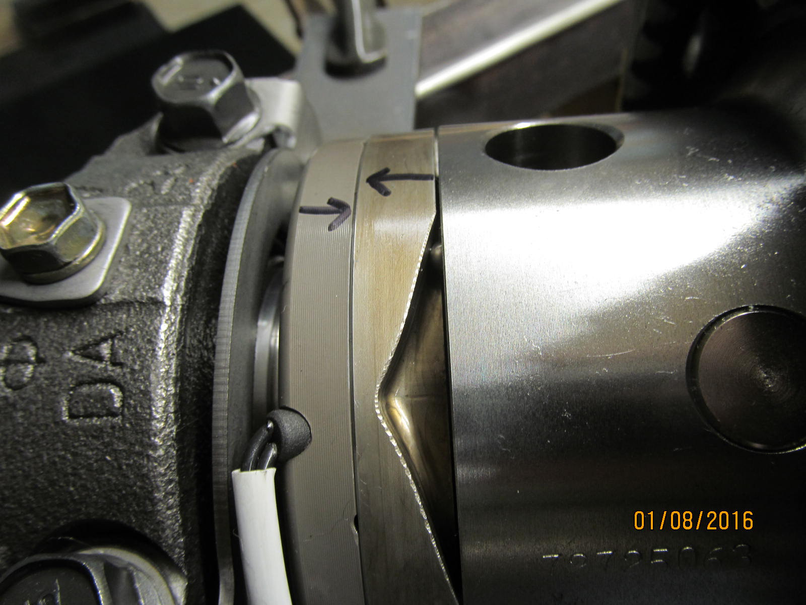
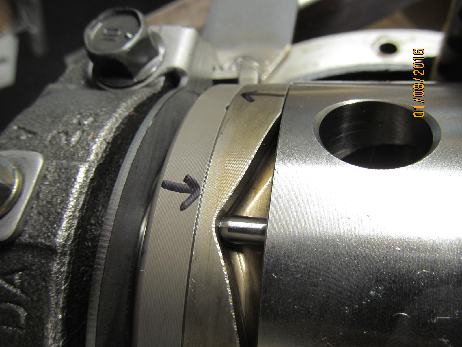
Page 6 step 21 of the online instructions talks of an approximate 2mm of radial freeplay for the
anti-rotation tabs. See those 2 welds on the tab? I did not want to stress them in any way so
light taps to the bracket allowed me to get the 2mm of play.
|
|
|
|
|
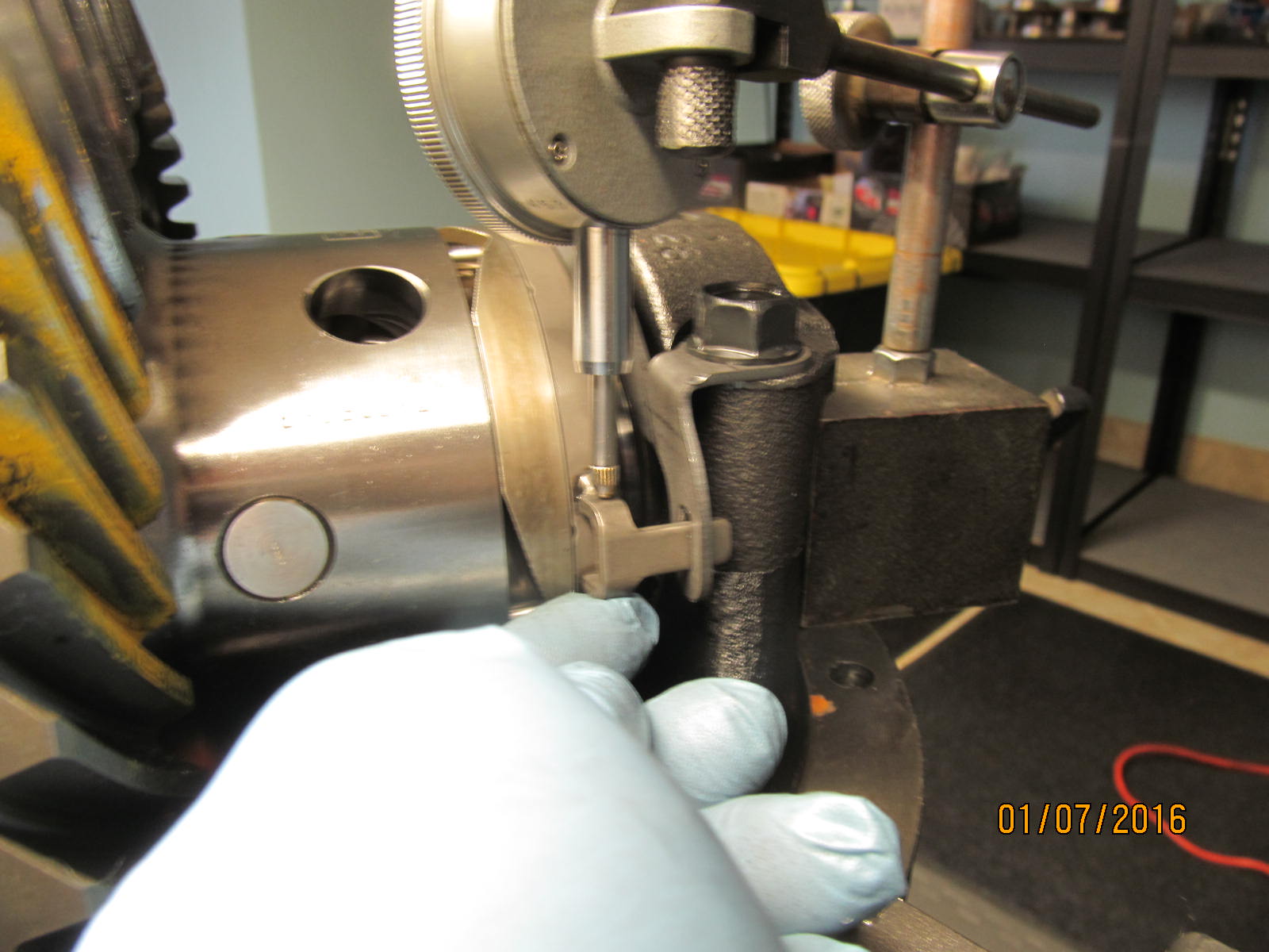
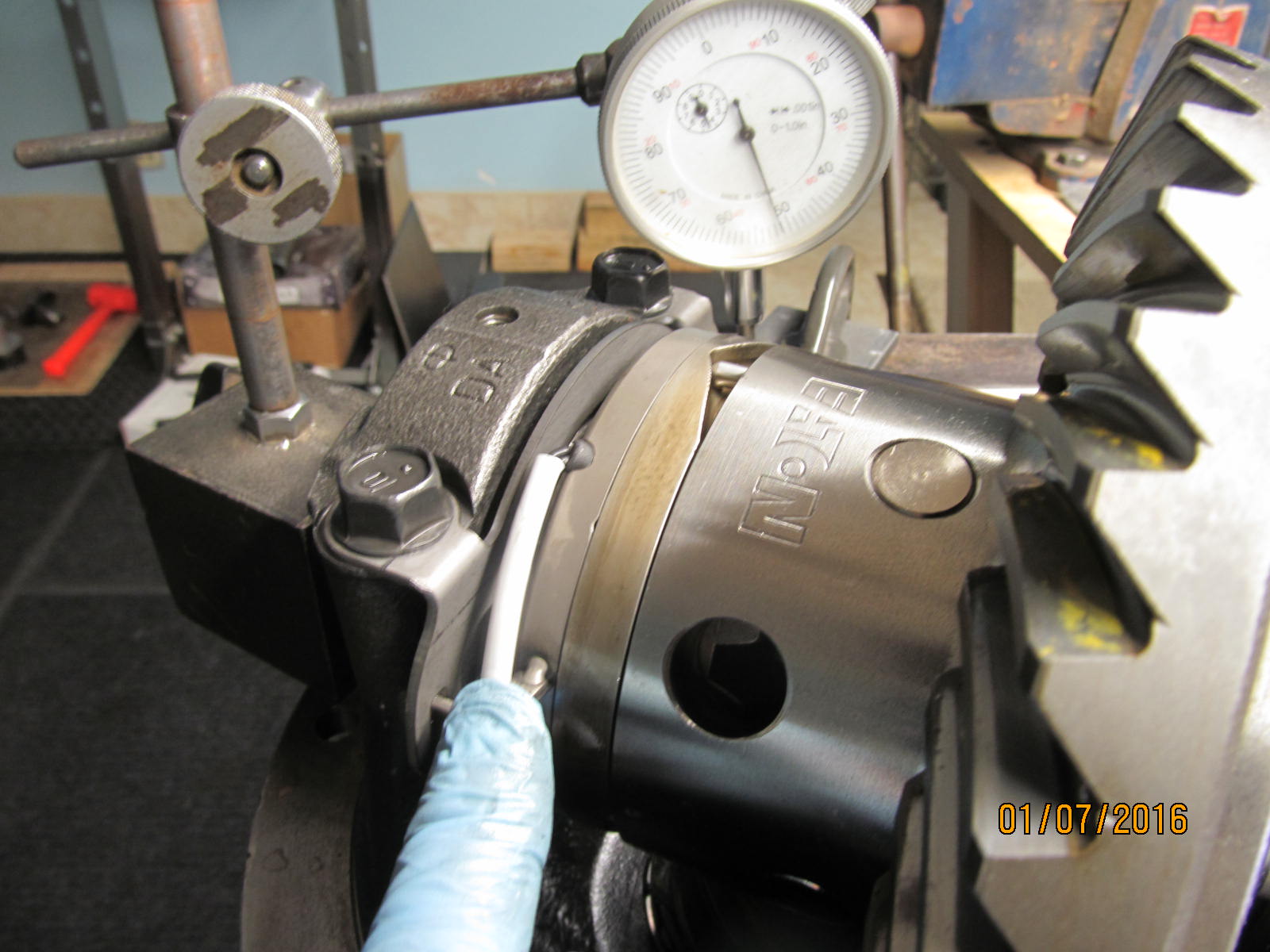
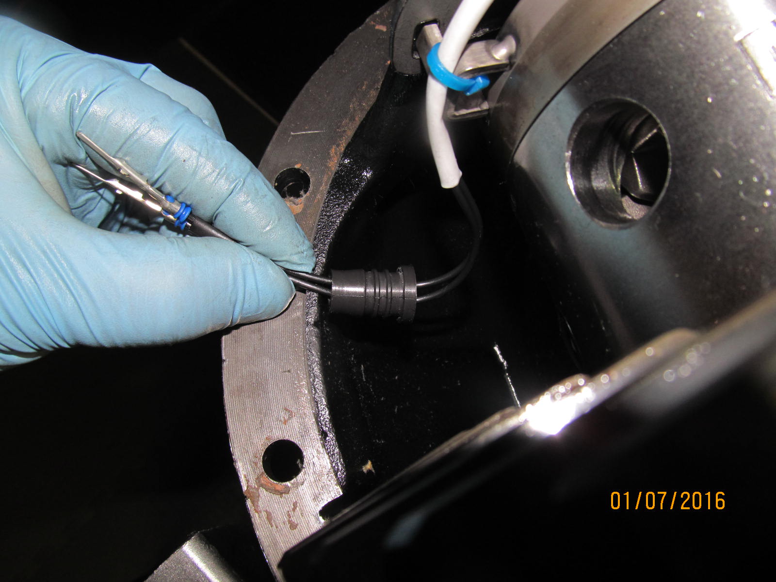
Checking radial freeplay here....
|
|
|
|
|
................
|
|
|
|
|
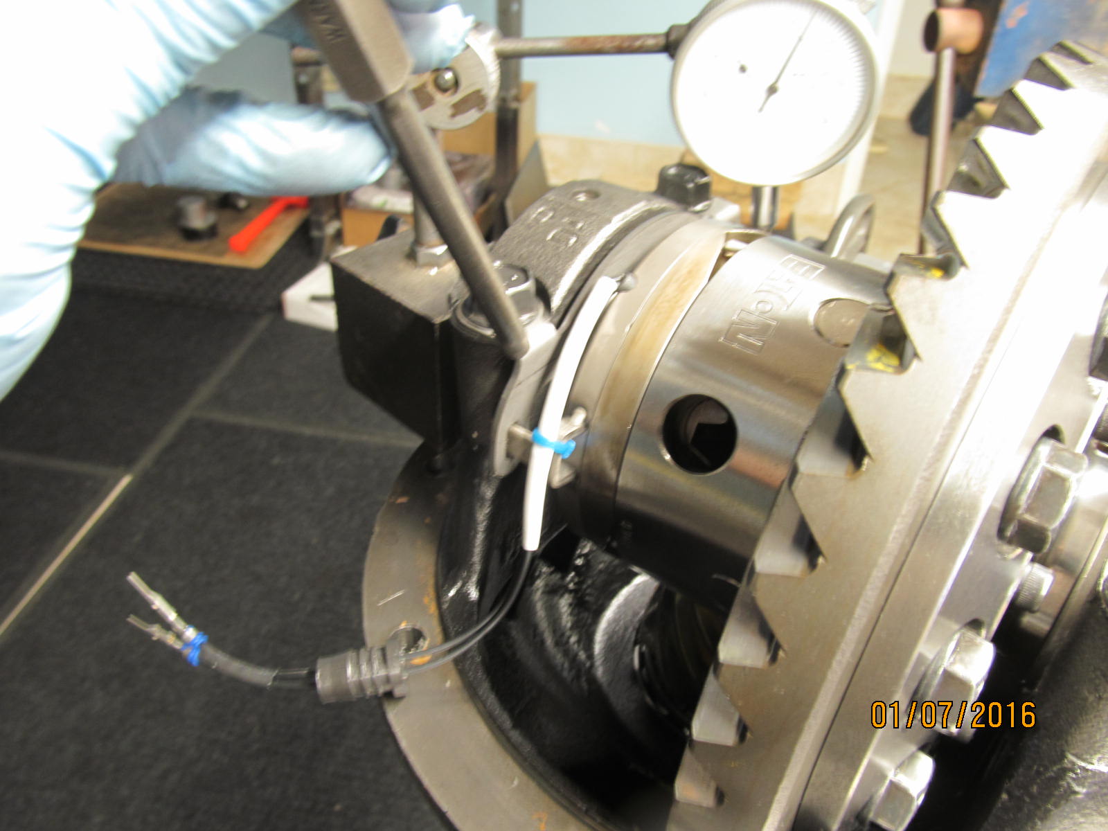
A light tap right here allows for plenty of play.
|
|
|
|
|
Light taps to persuade the soft steel bracket to move just a little.
|
|
|
|
|
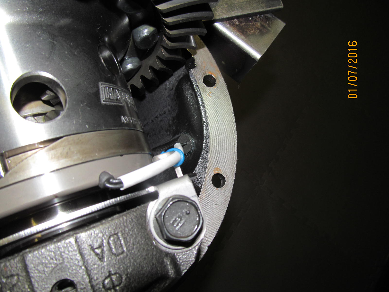
Ready for drilling the hole for this pass-thru grommet.
|
|
|
|
|
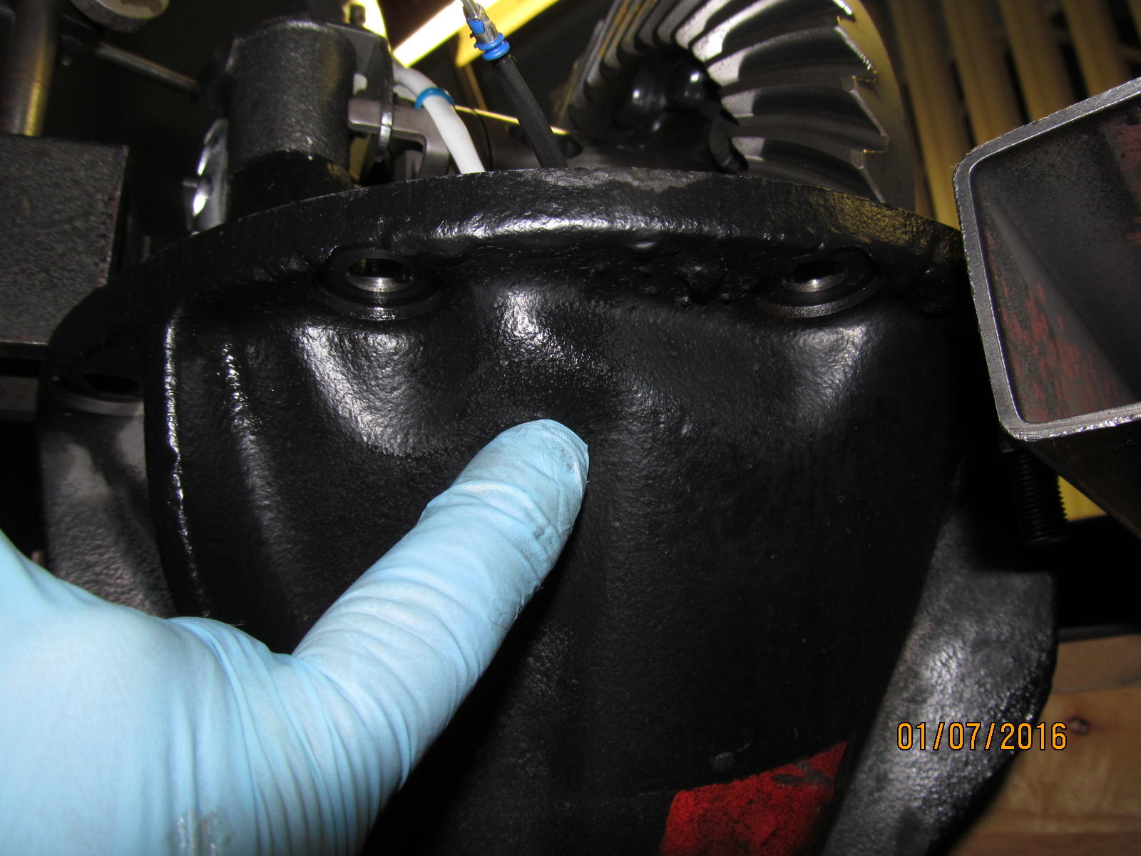
This is the spot I chose.
|
|
|
|
|
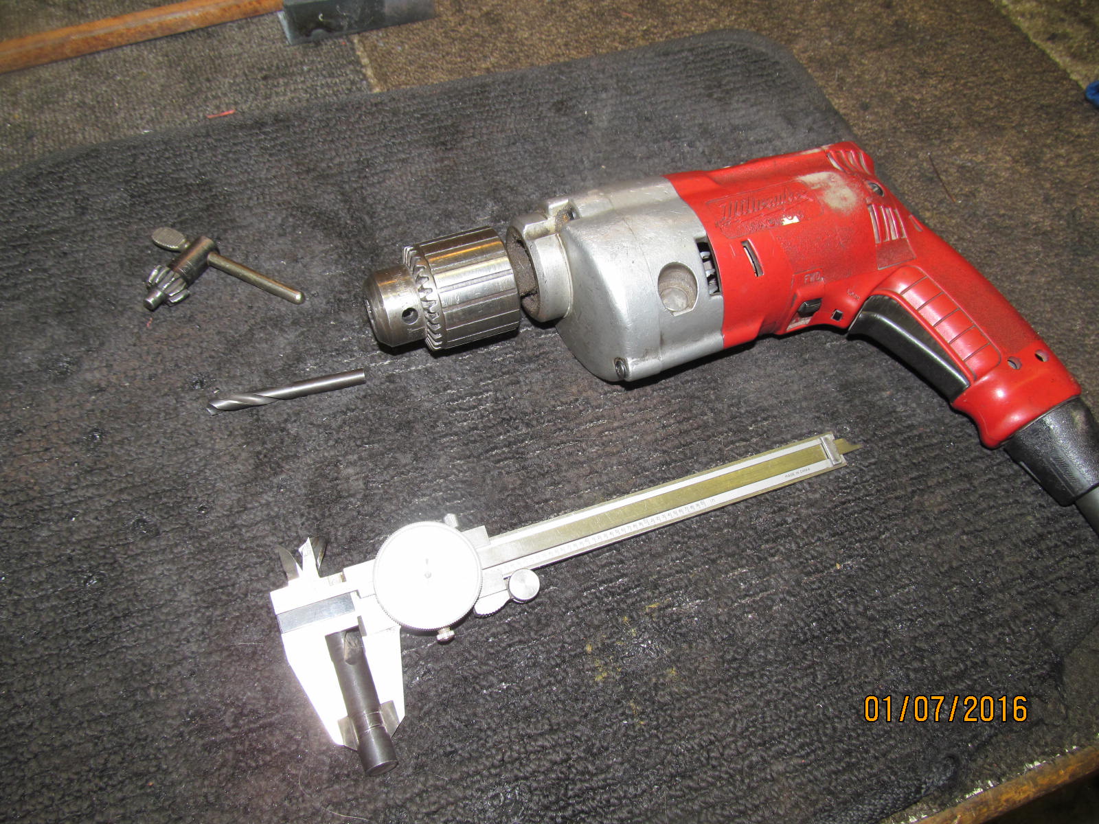
Page 6 of the instructions talks of a 29/64 drill bit (.453")
|
|
|

|
|
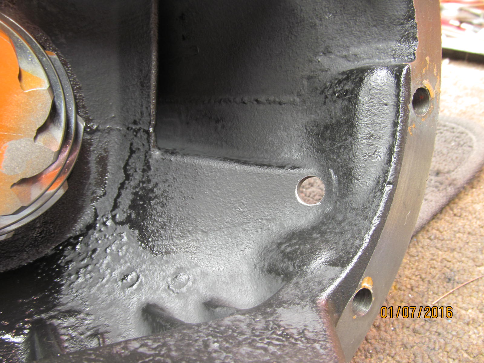
Hole is drilled.
|
|
|
|
|
...............
|
|
|
|
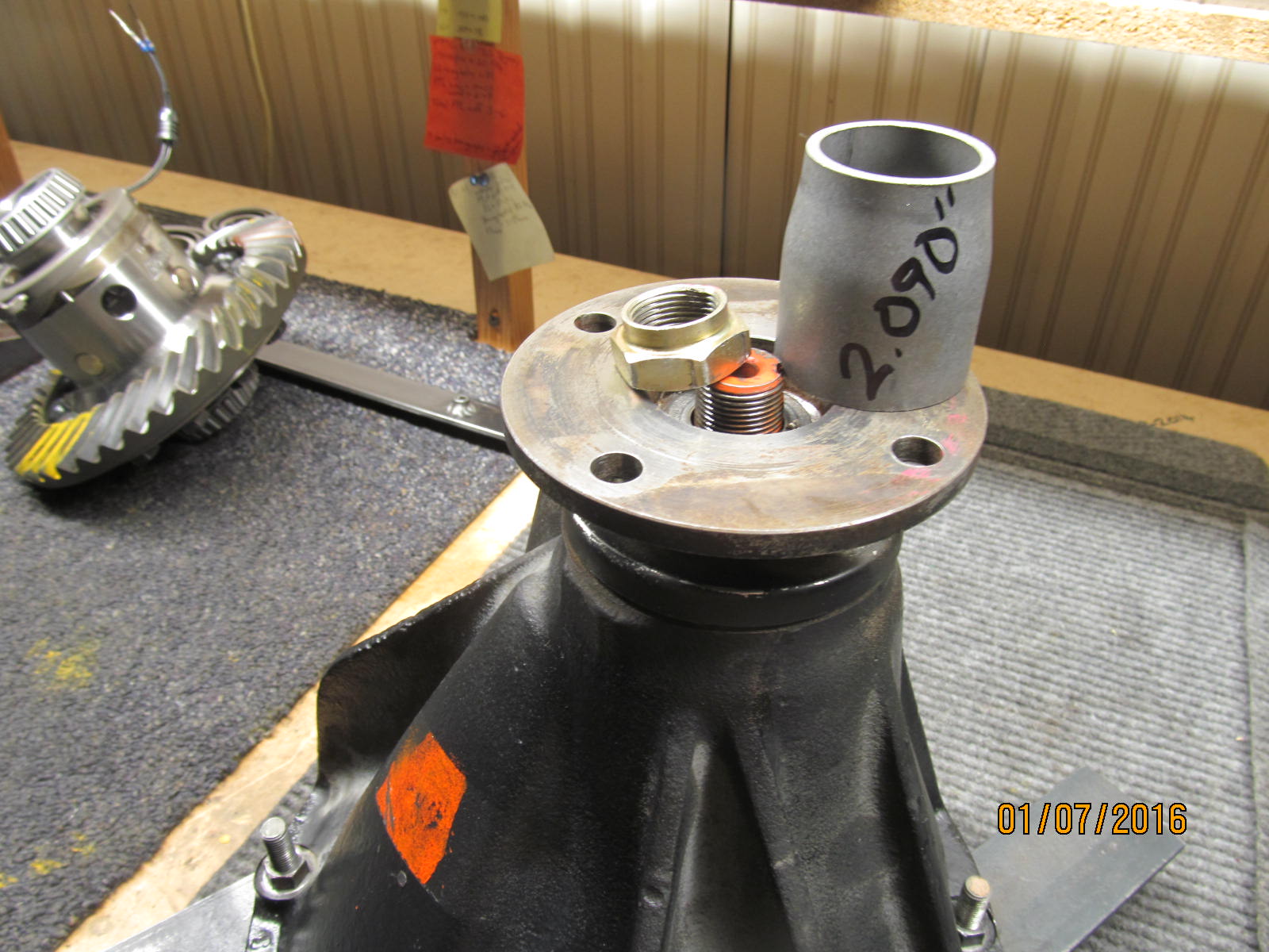
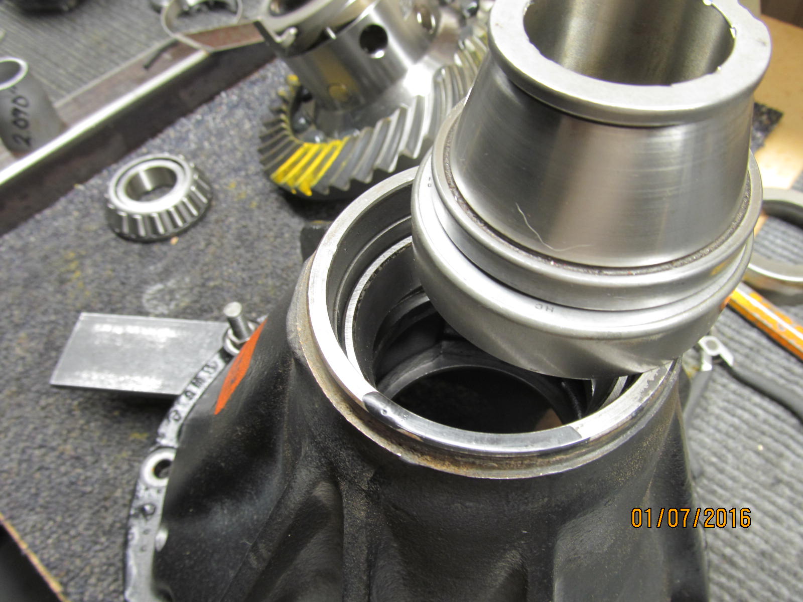
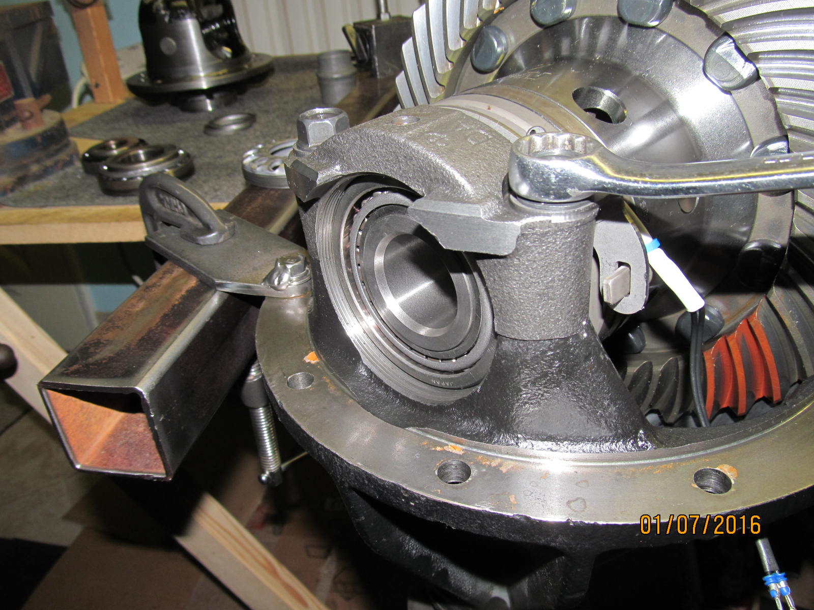
Time to put the solid collar and new pinion bearings in. This is normally
not done on a basic Harrop Install.
|
|
|
|
|
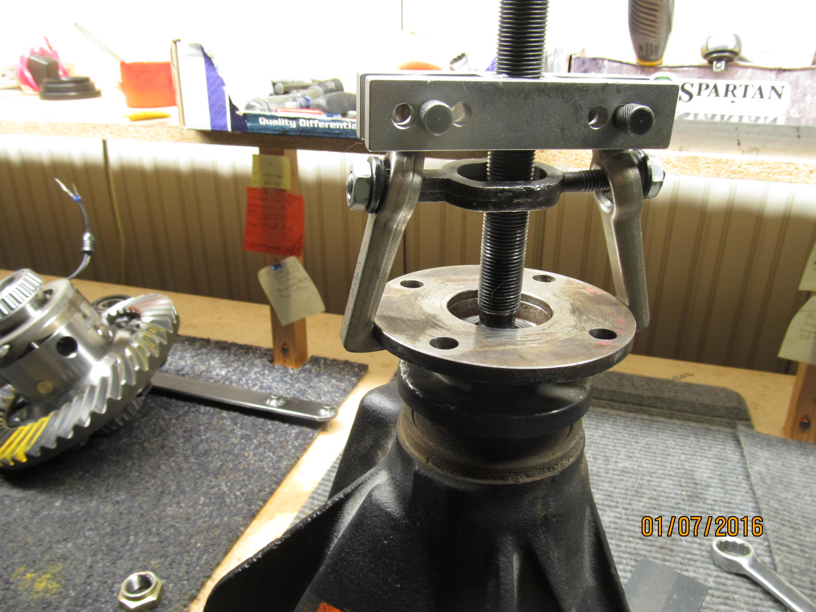
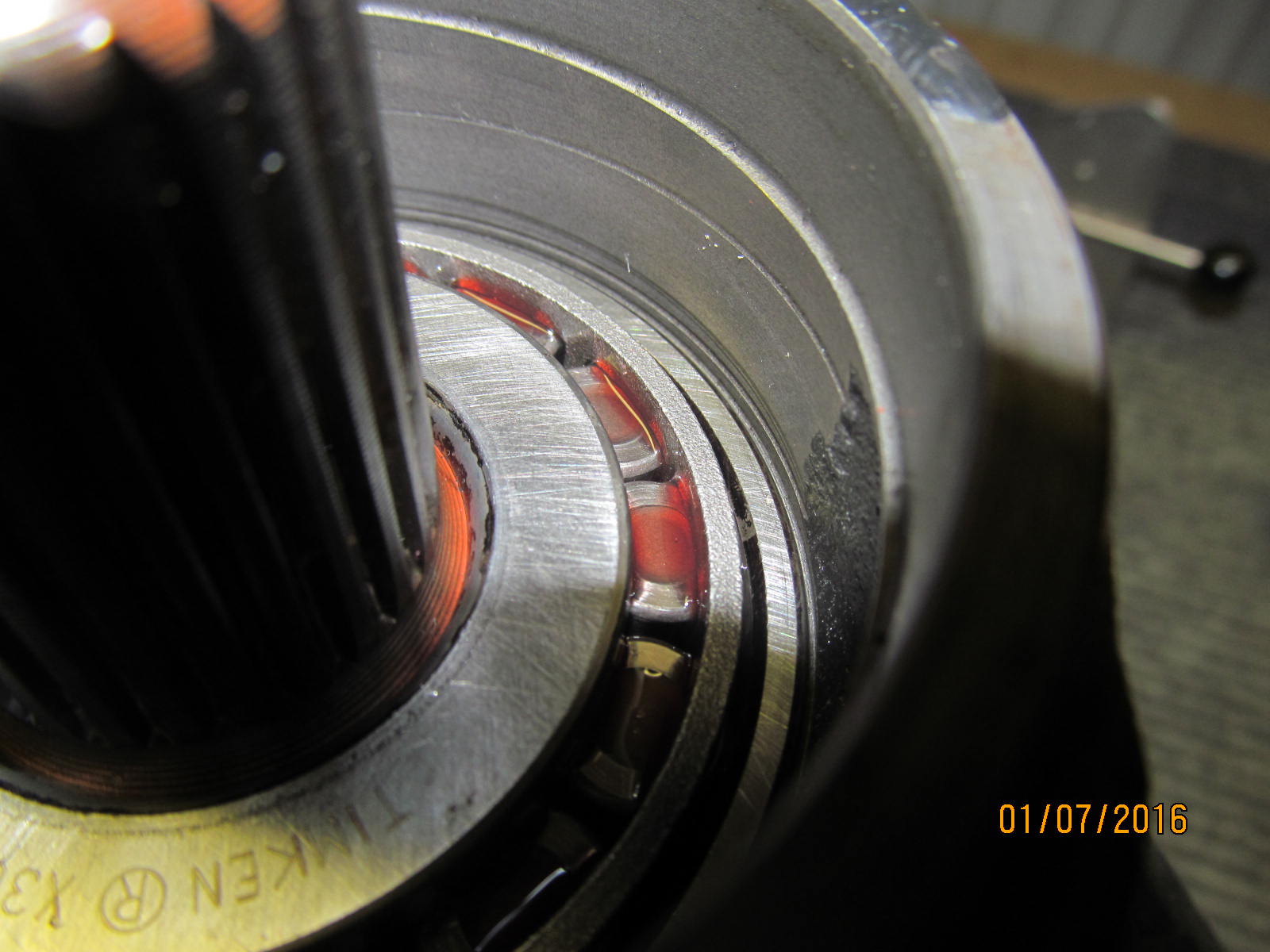
Flange was a tight fit.
|
|
|
|
|
Push the pinion out.
|
|
|
|
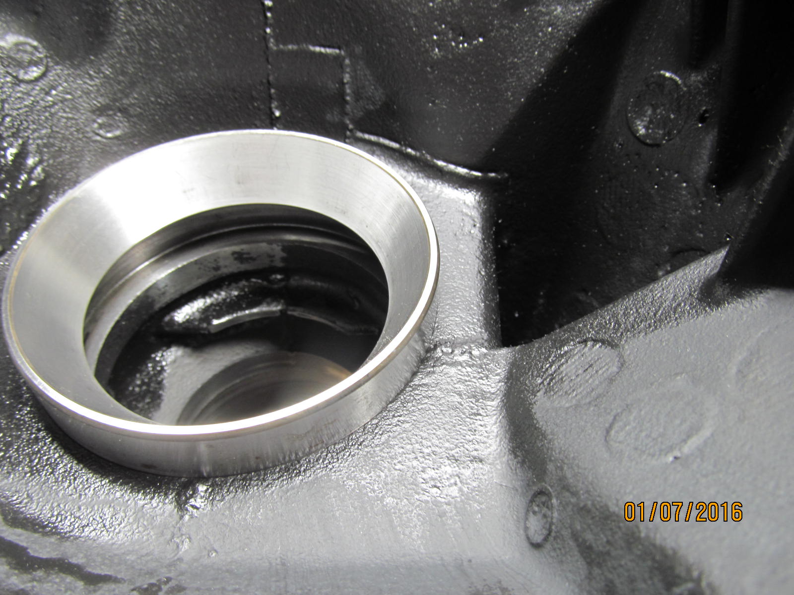
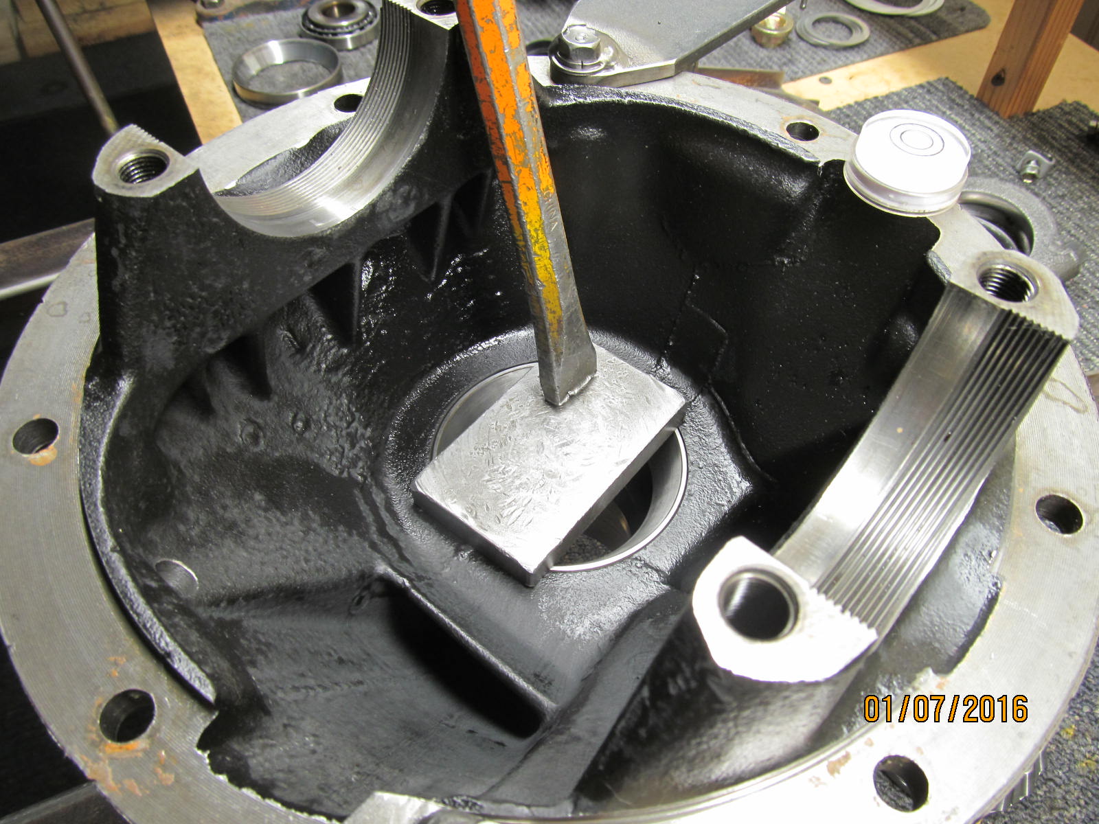
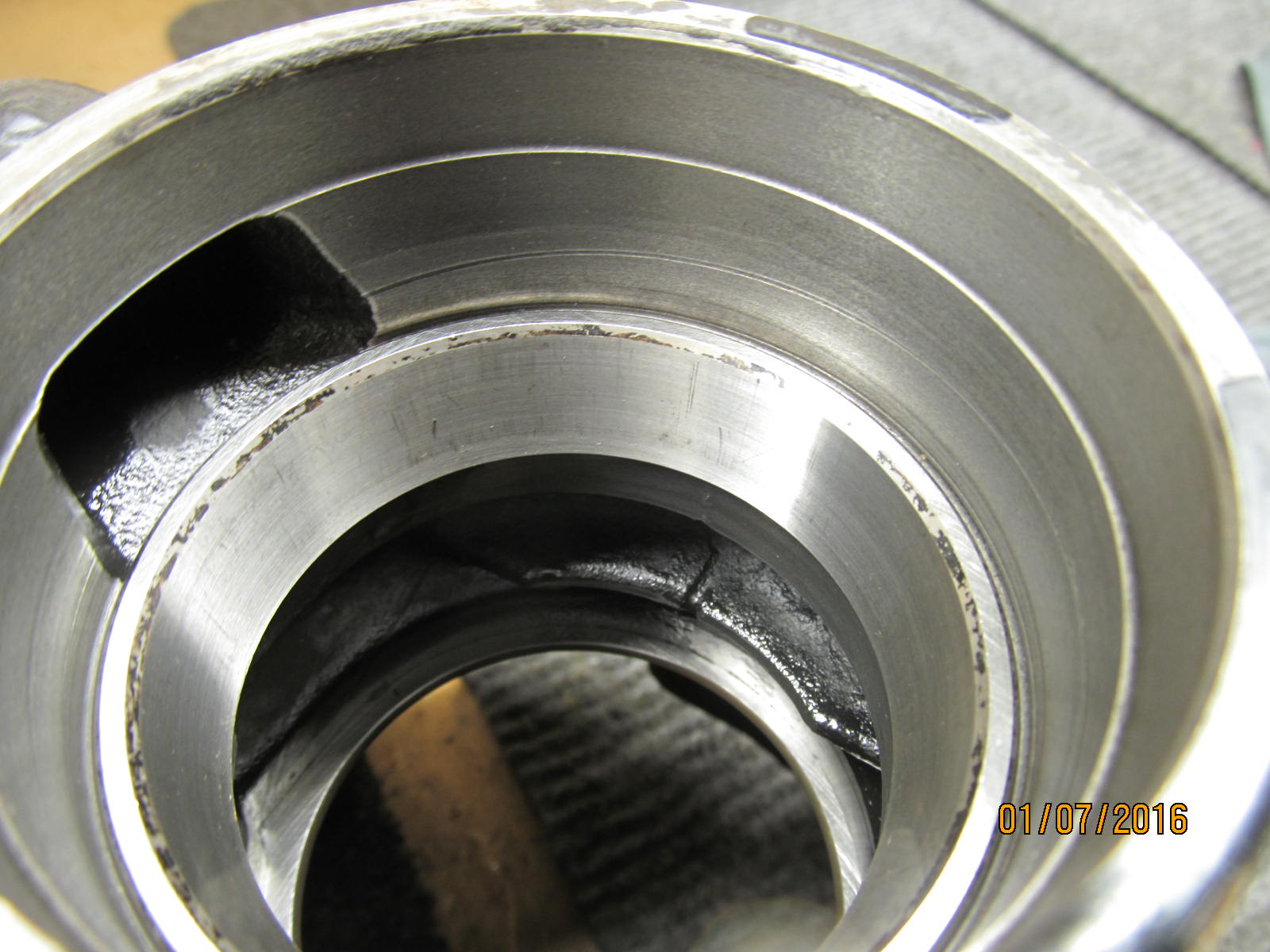
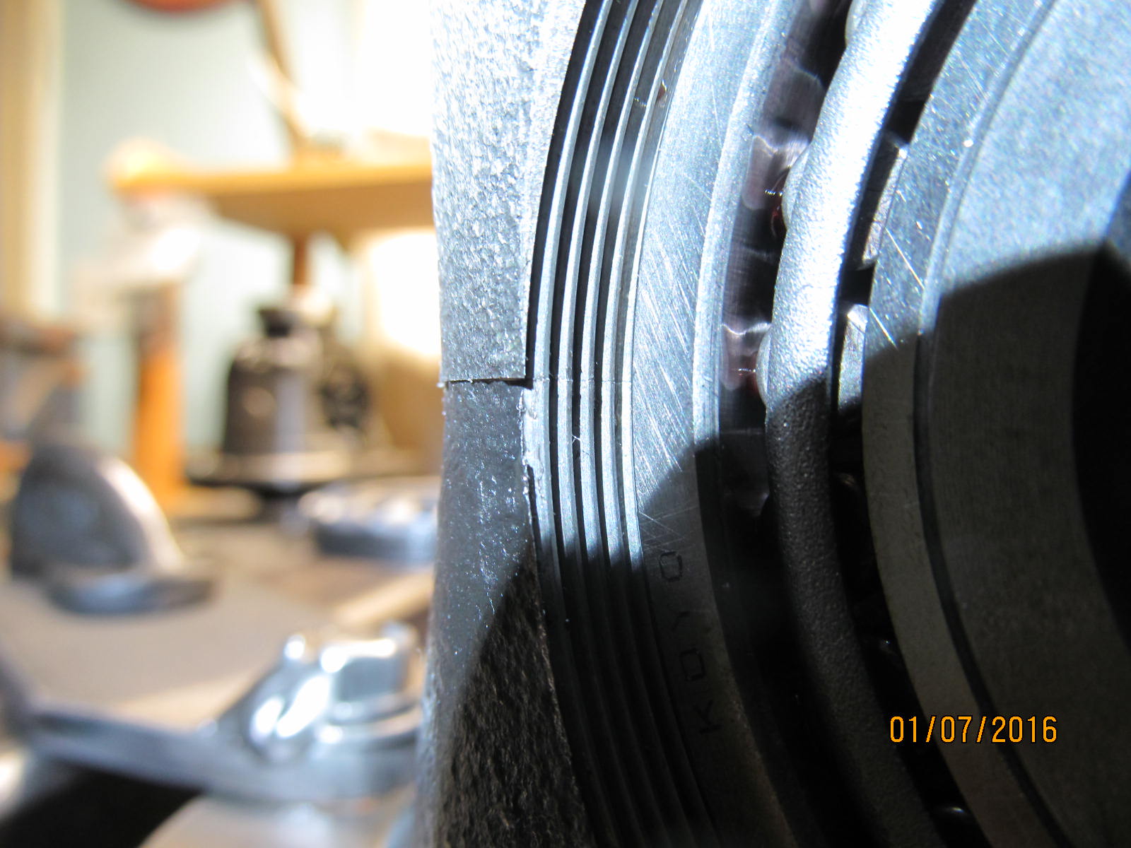
New large inner race is to be tapped/pressed in. The trick is to get it started straight and then it
will fall in the hole with gentle words.
|
|
|
|
|
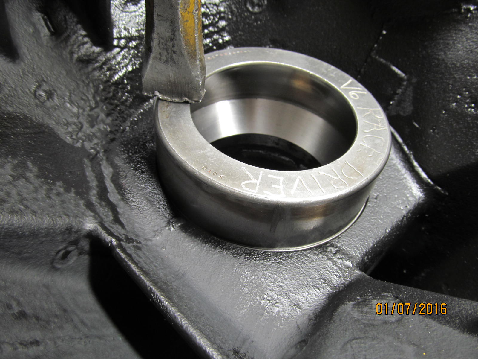
Success....almost down all the way.
|
|
|
|
|
Using an old race, the final taps will seat it the remaining few millimeters.
|
|
|
|
|
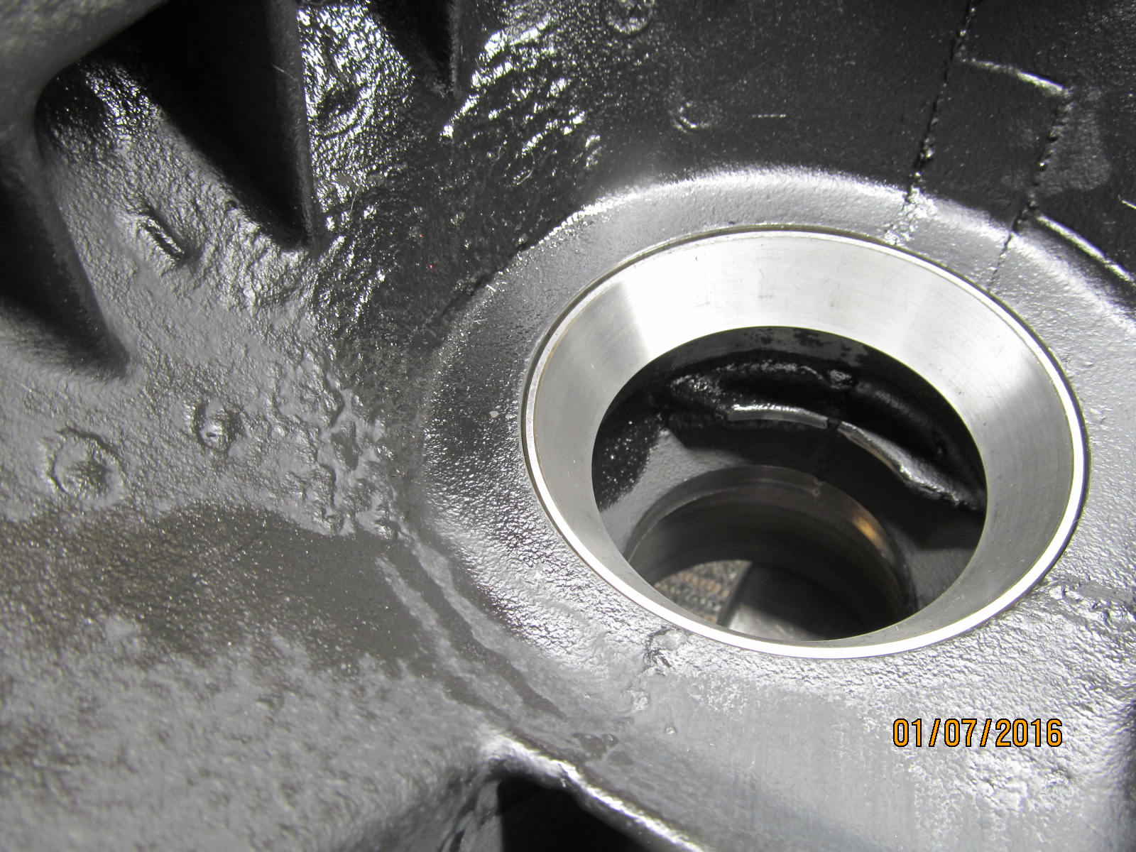
Verified fully down.
|
|
|
|
|
The outer one is much easier.
|
|
|
|
|
Fully seated.
|
|
|
|
|
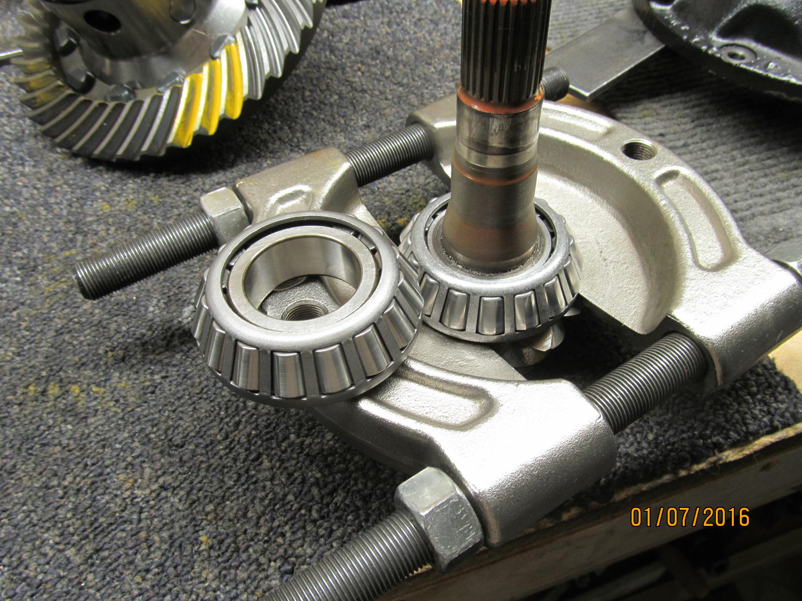
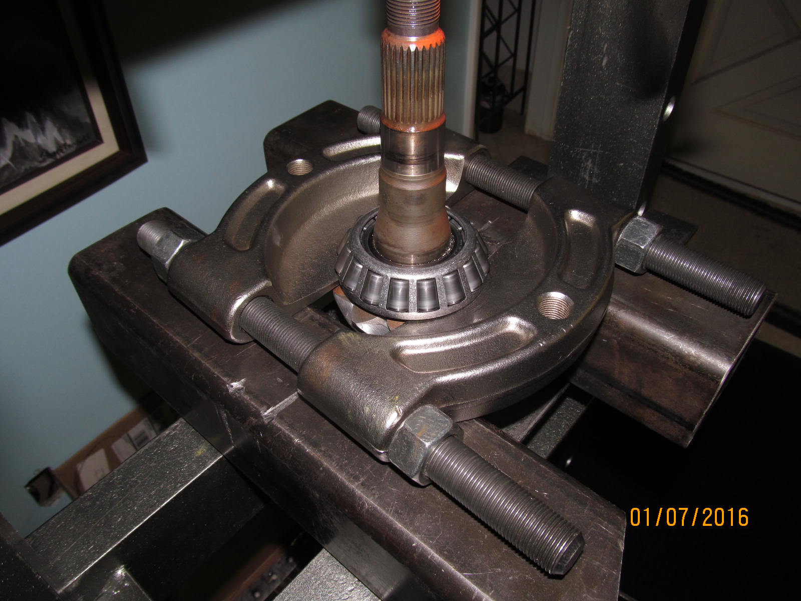
This bearing separator will remove the old pinion bearing.....
|
|
|
|
|
....with the help of the 12 ton Harbor Freight press.
|
|
|
|
|
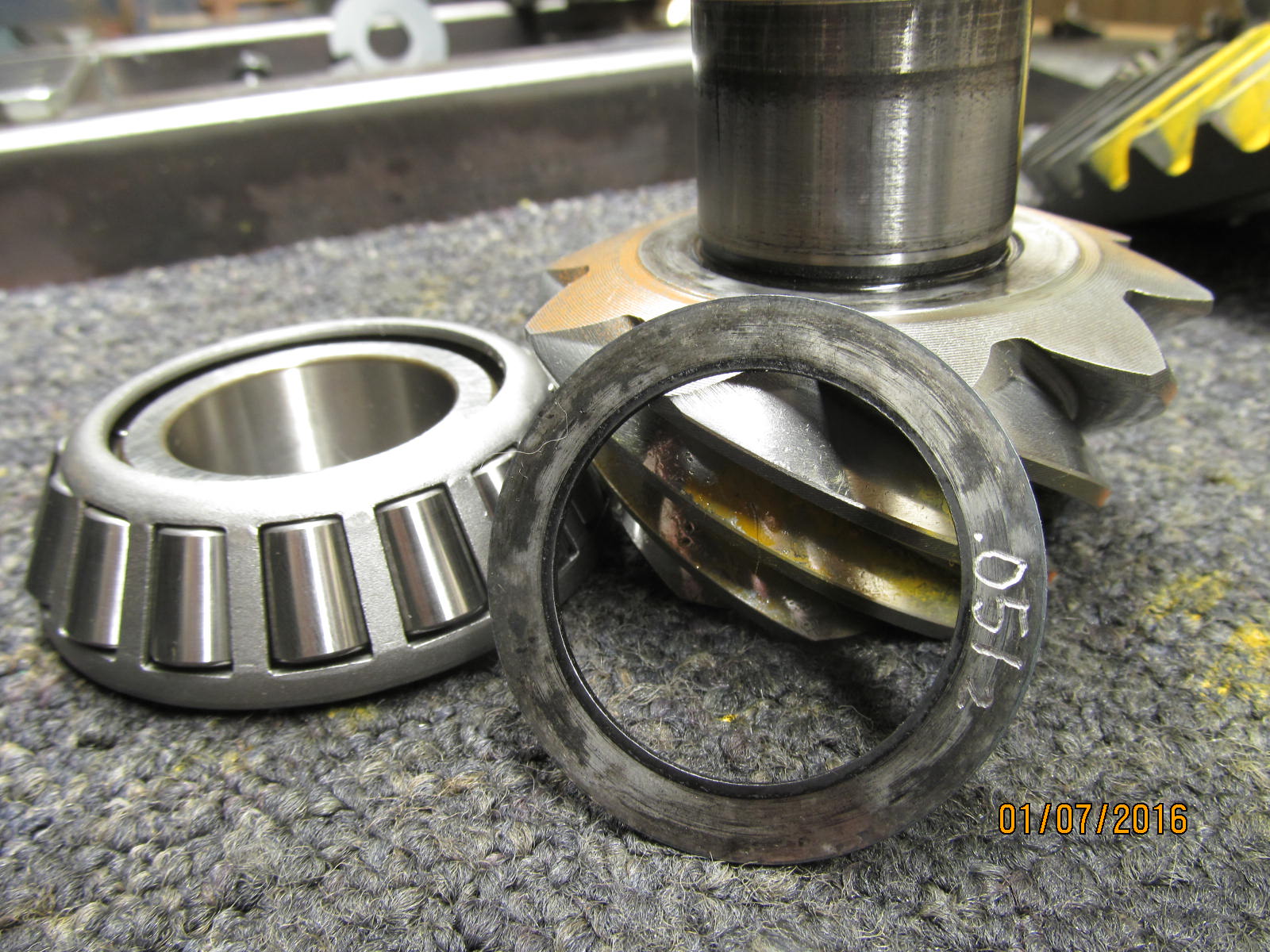
The new bearing will be pressed on with the oem .051" shim.
|
|
|
|
|
The tubular widget I made up works superbly for this job.
|
|
|
|
|
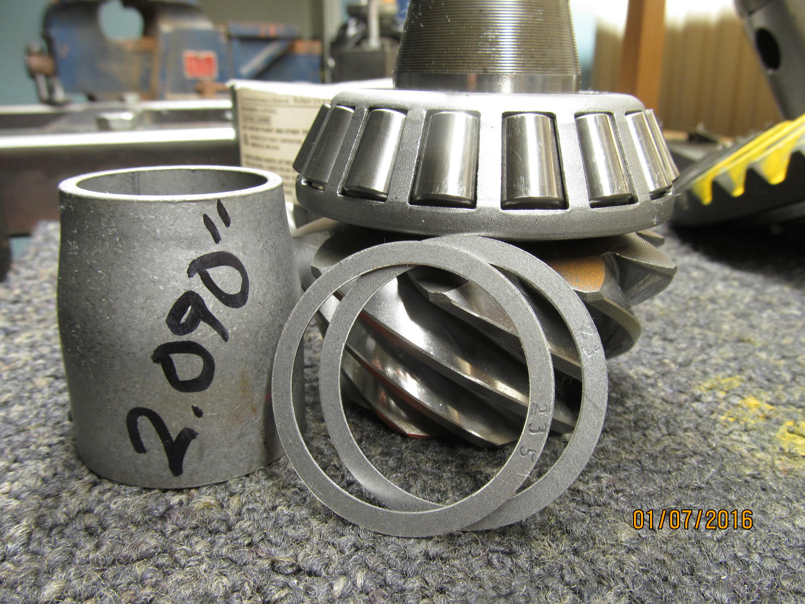
The collar measured 2.090" and with the addition of .0465" worth of shims should put me close to the target.
|
|
|
|
|
Nope....no preload at all.
|
|
|
|
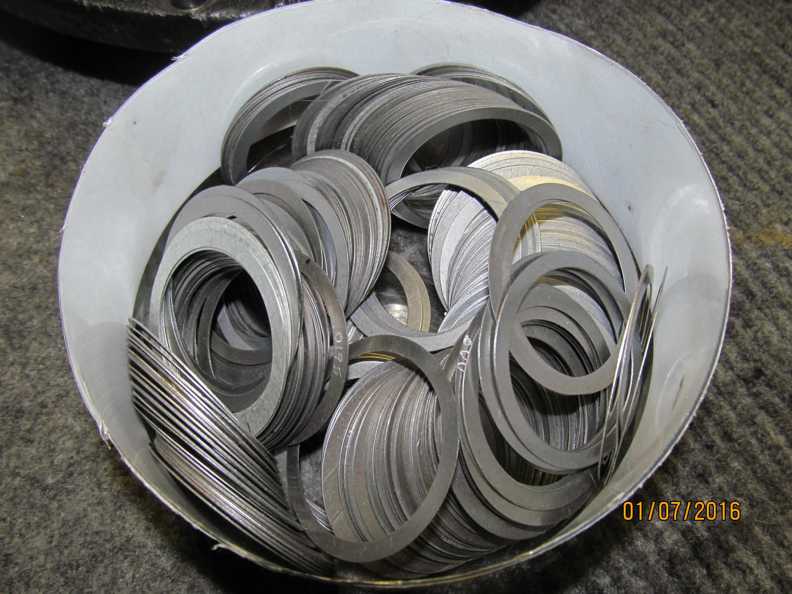
It's good to have a broad selection of collar shims. On try #2, I reduced the thickness of the shim
by .003" and that did the trick.
|
|
|
|
|
Last chance to lube up the bearings for smooth readings.
|
|
|
|
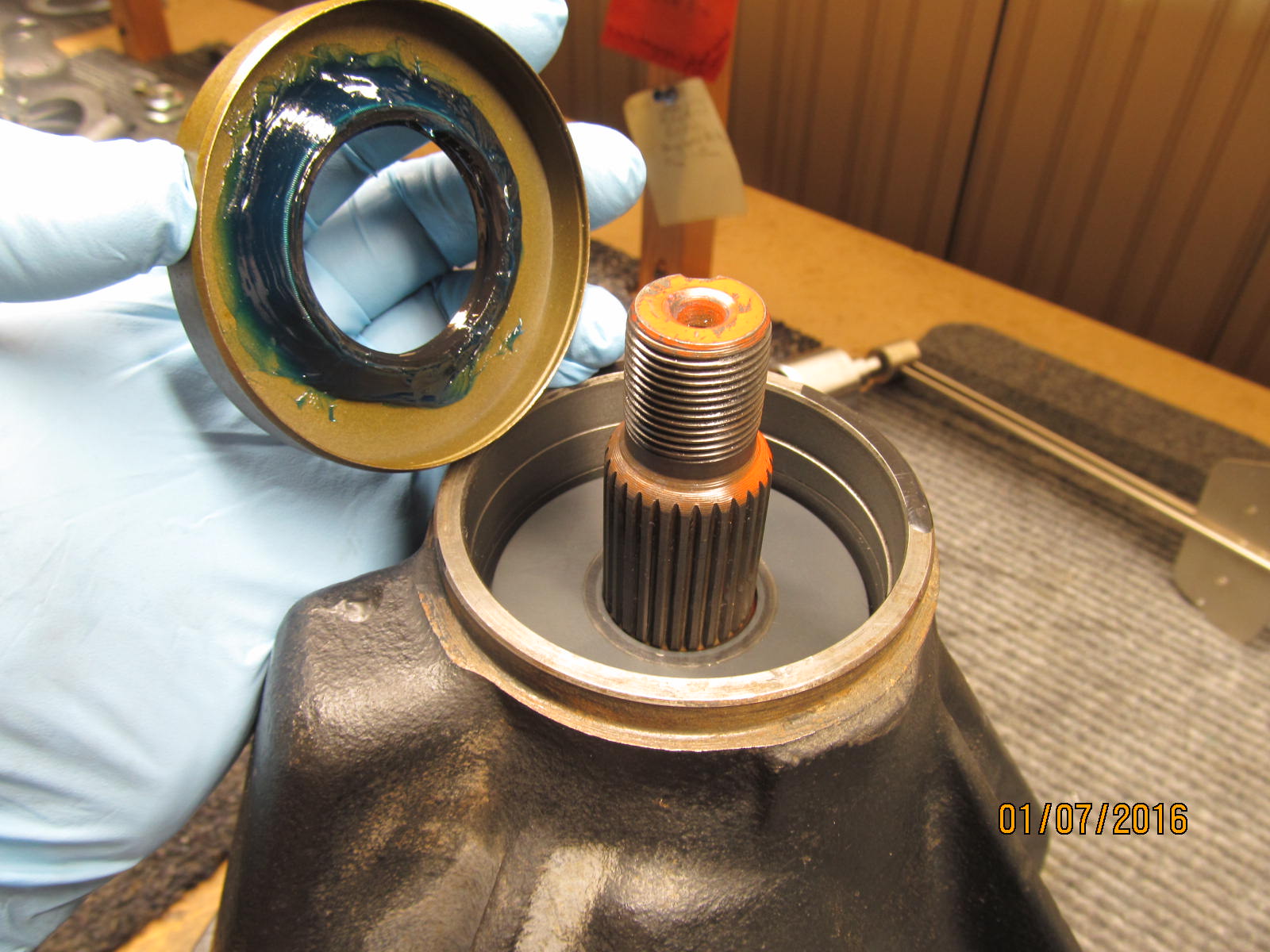
The new seal is packed with grease around the garter spring to prevent it from popping off from
shock waves caused by the hammer.
|
|
|
|
|
..............
|
|
|
|
|
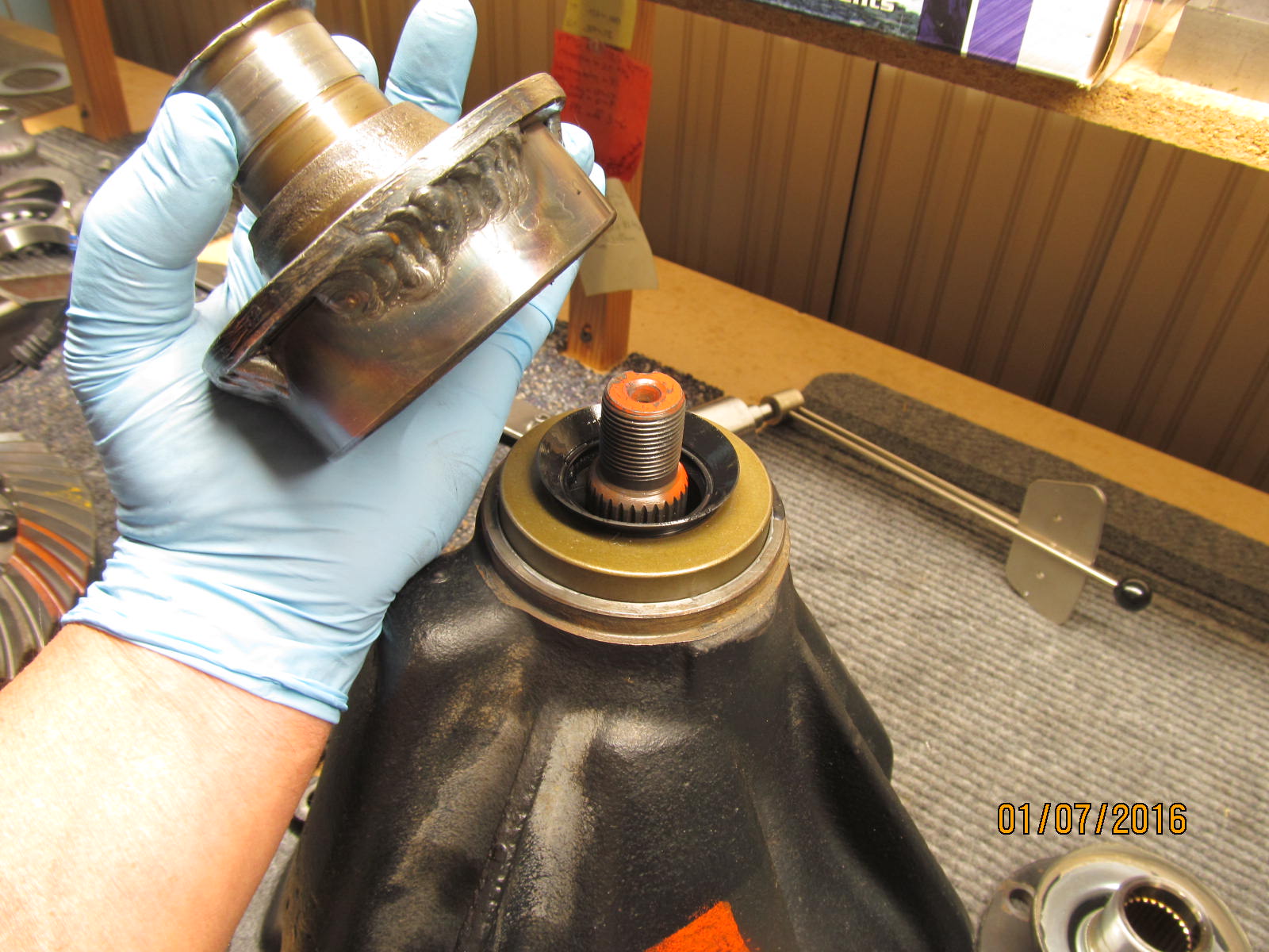
Often, I use aluminum anti-seize when I anticipate that I will be really cranking down on the nut.
|
|
|
|
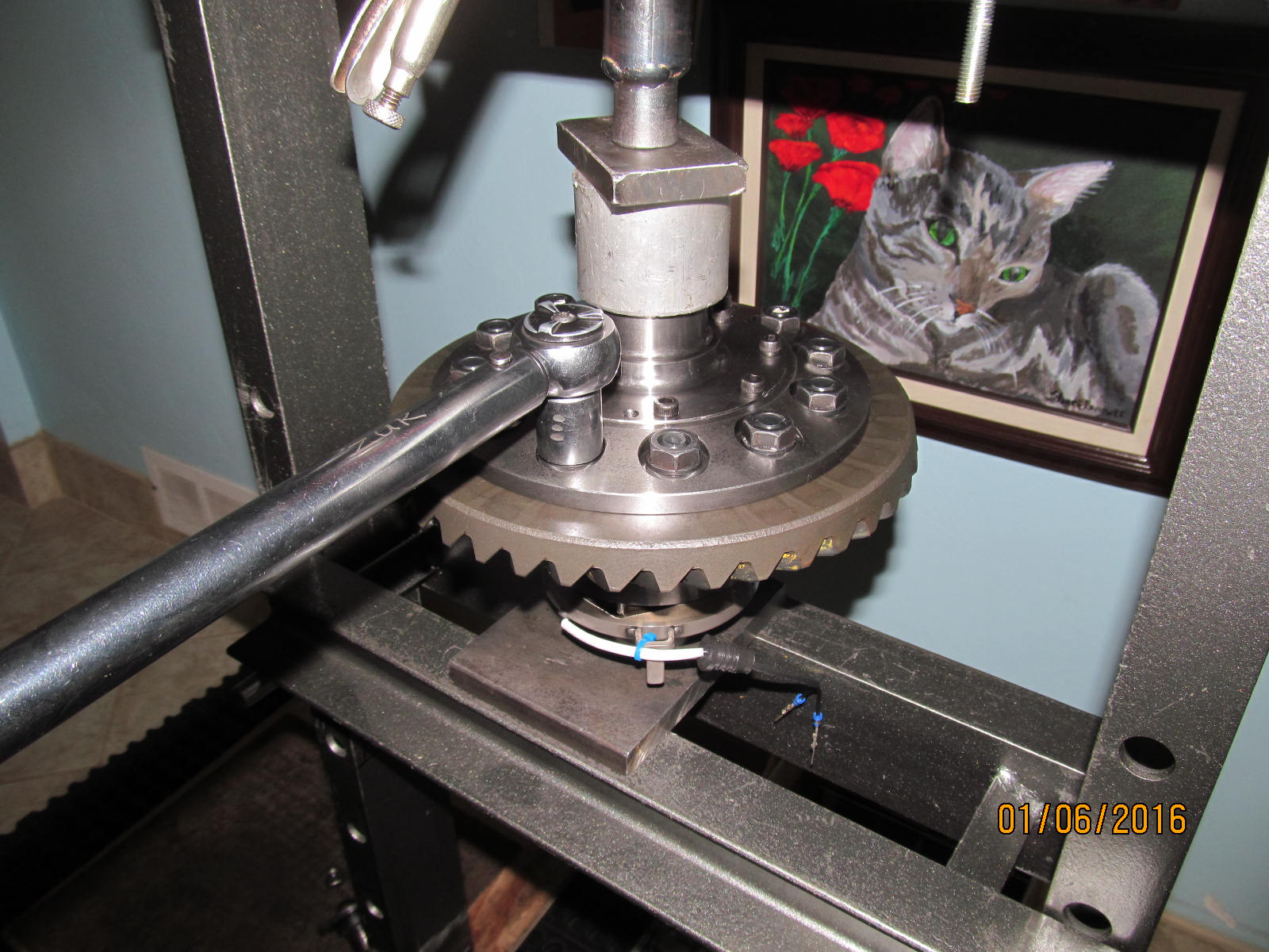
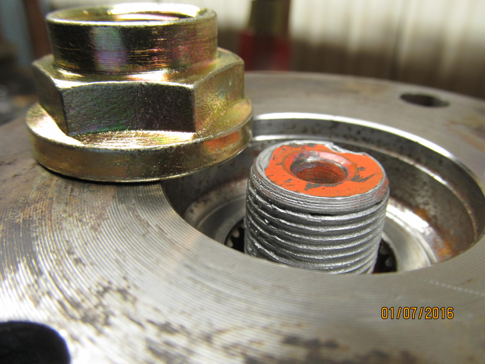
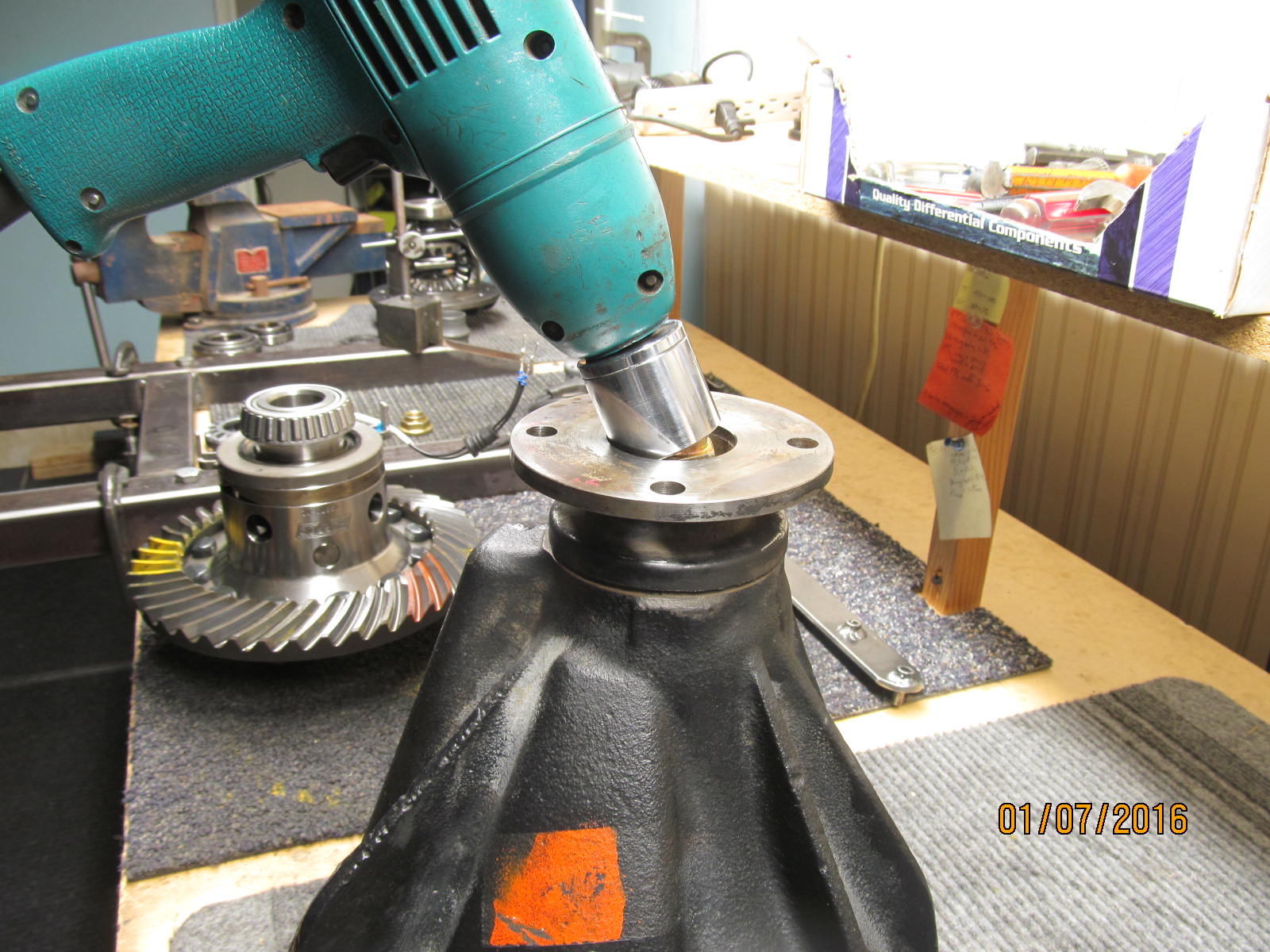
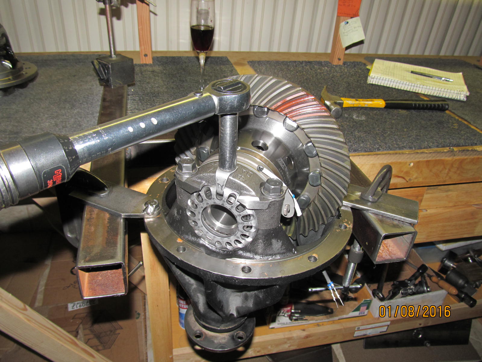
I use the electric impact to tighten it down 90%....then I break out the cheater bar for
the final tweaking.
|
|
|
|
|
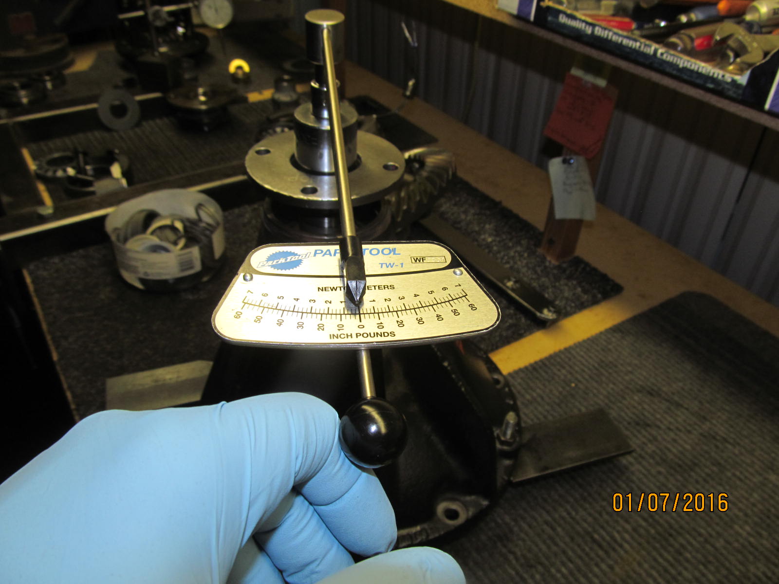
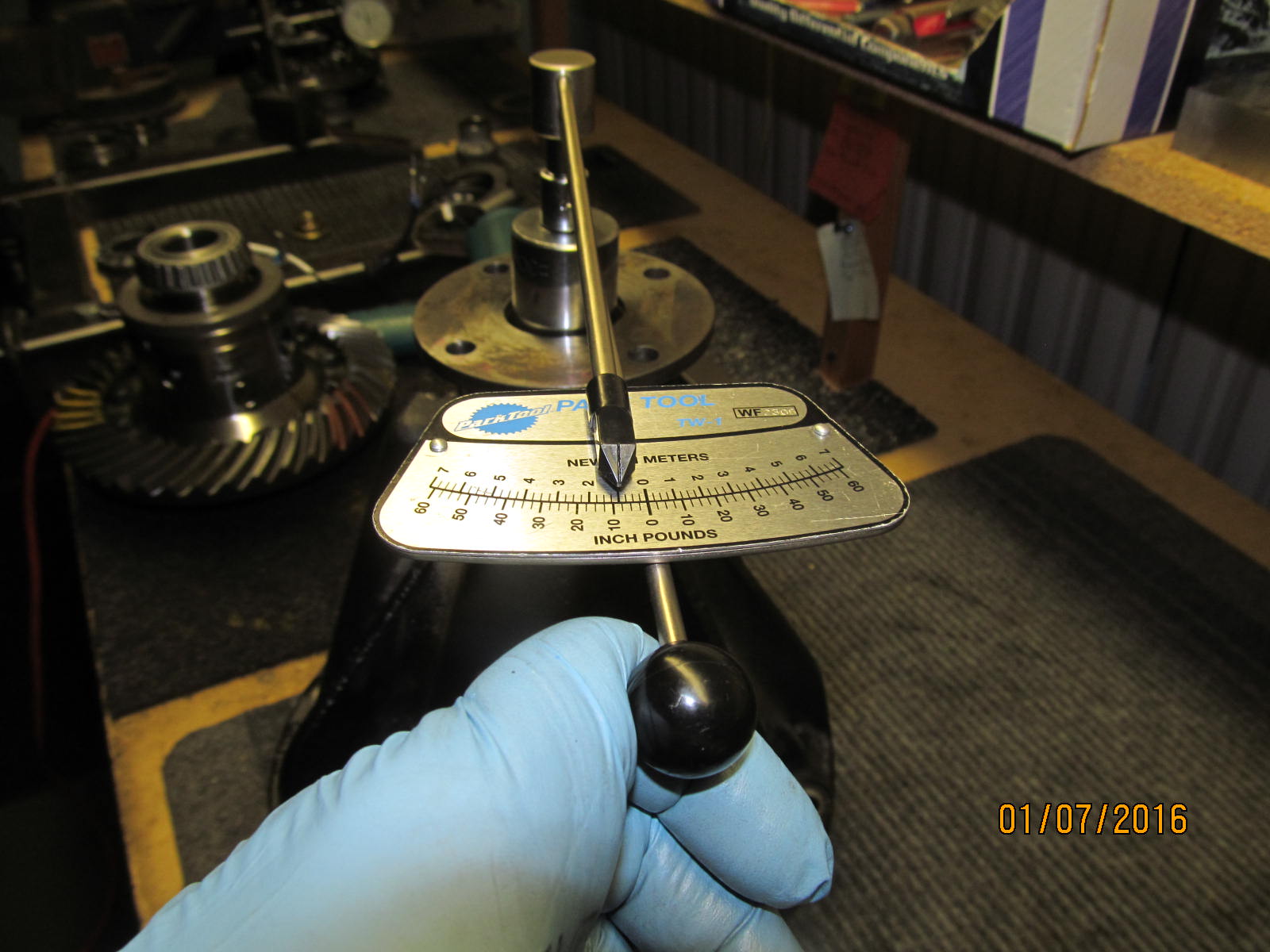
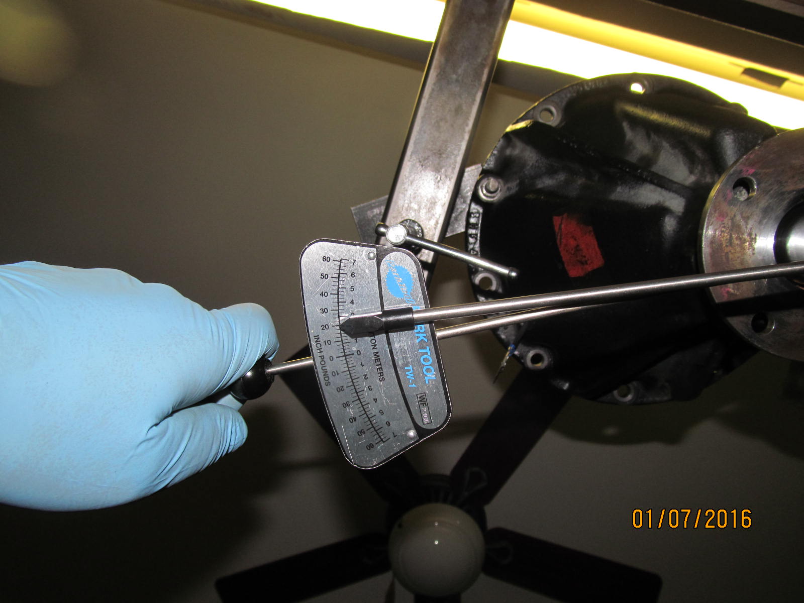
8 inch/lb.....I can get the pre-load higher by using a cheater bar.
|
|
|
|
|
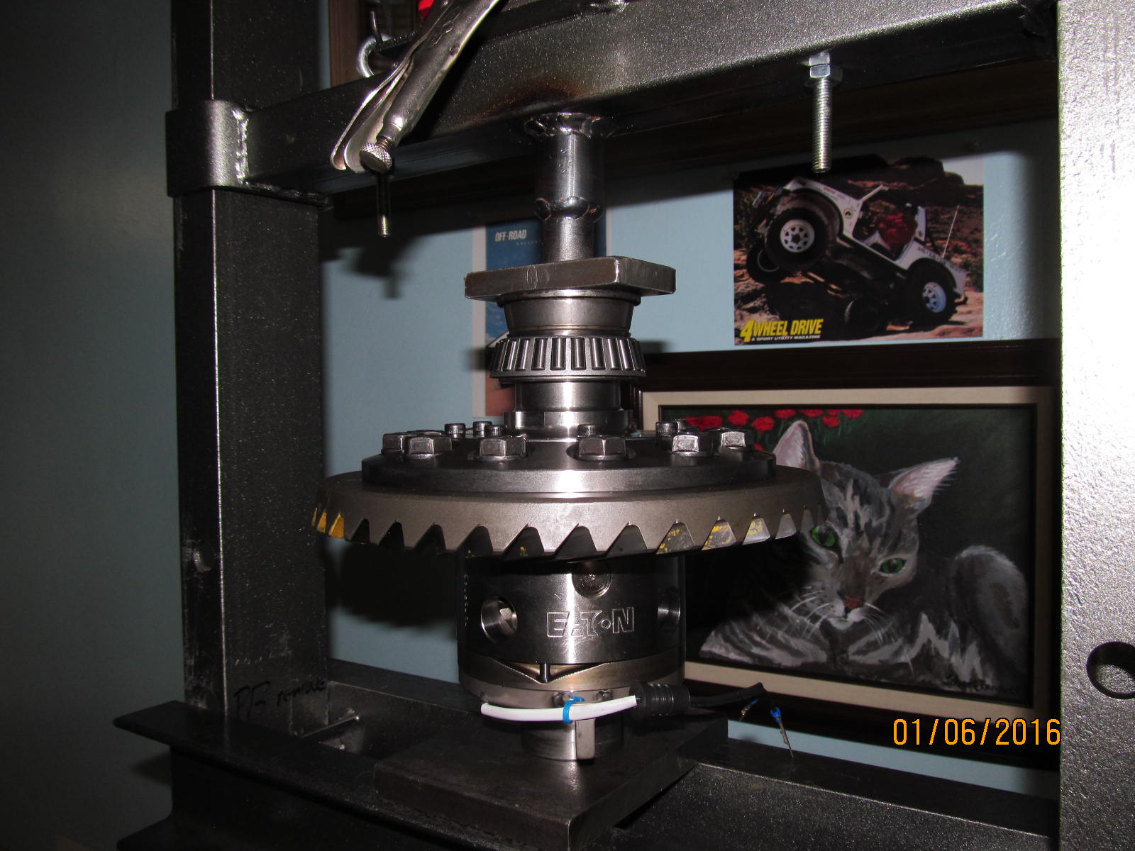
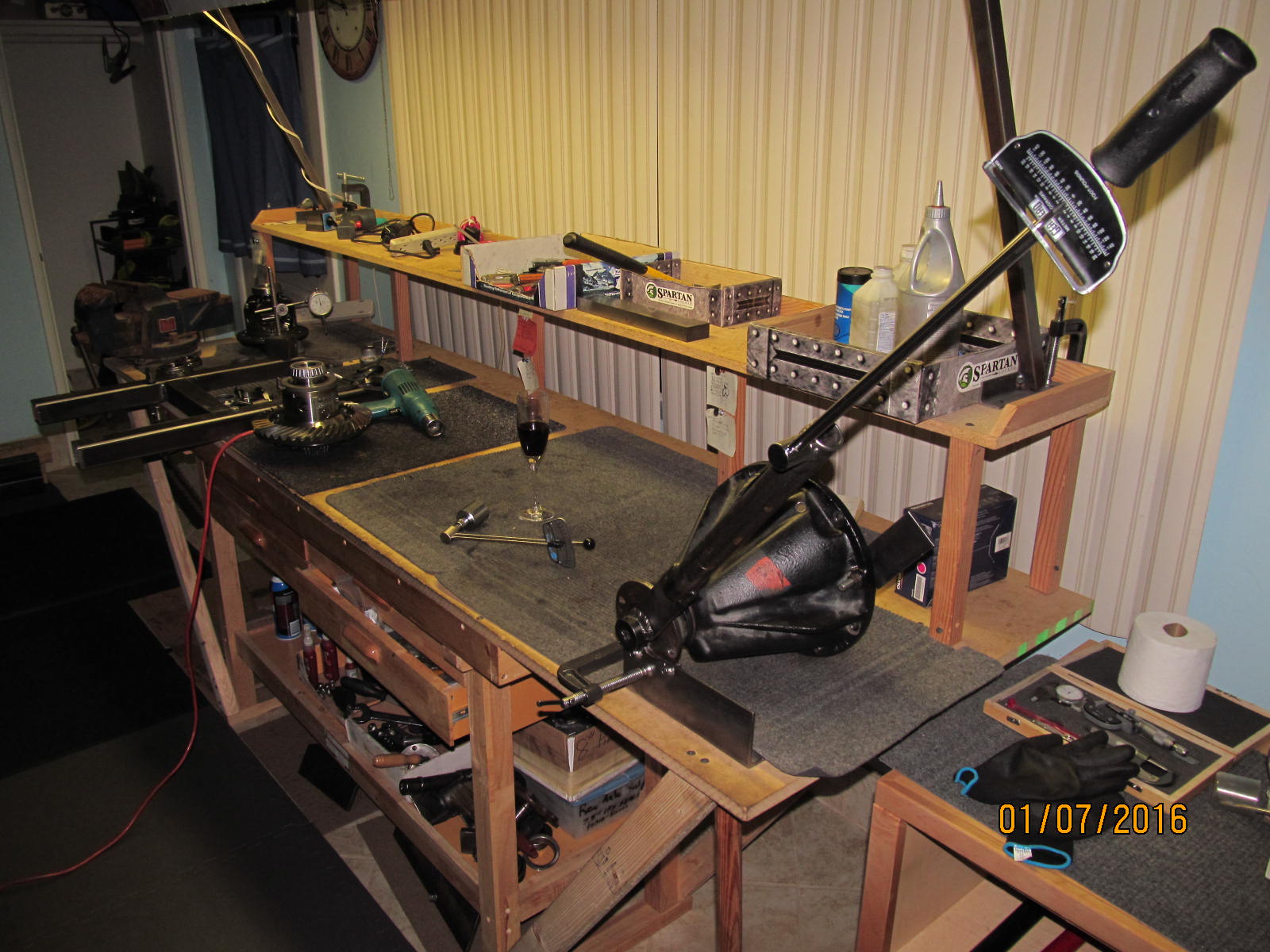
That's a 150 ft/lb rated typical pendulum style torque wrench. Attached is a doubler that allows for 300 ft/lb.
|
|
|
|
|
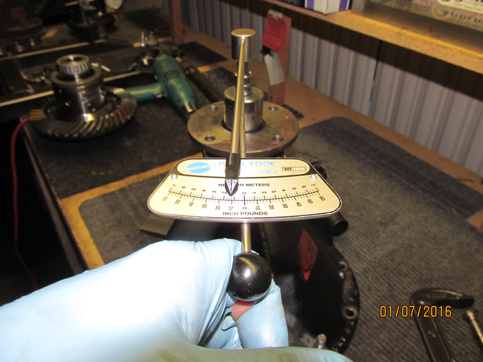
Even with the anti-seize, I did manage to reach 300 ft/lb and the preload is right at 10 maybe a smidge more.
|
|
|
|
|
DING.
|
|
|
|
|
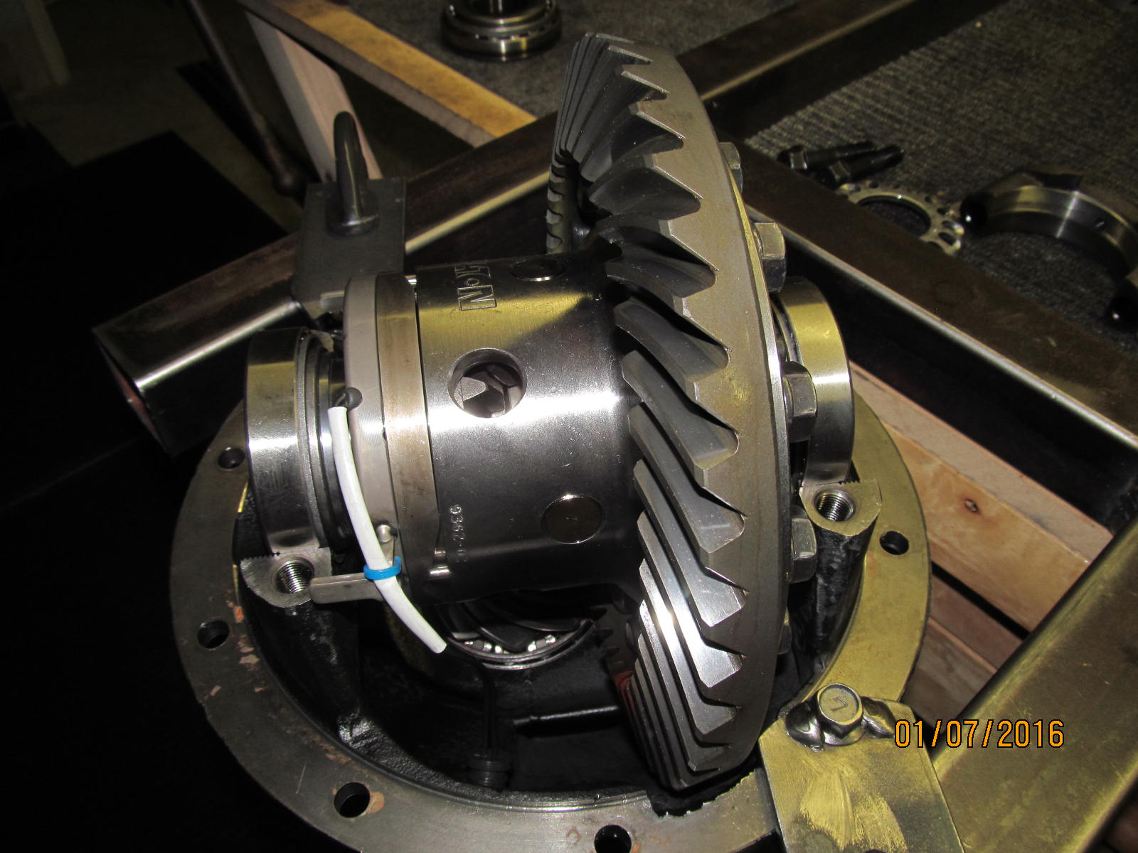
With the pinion end complete, now the final assembly can happen.
|
|
|
|
|
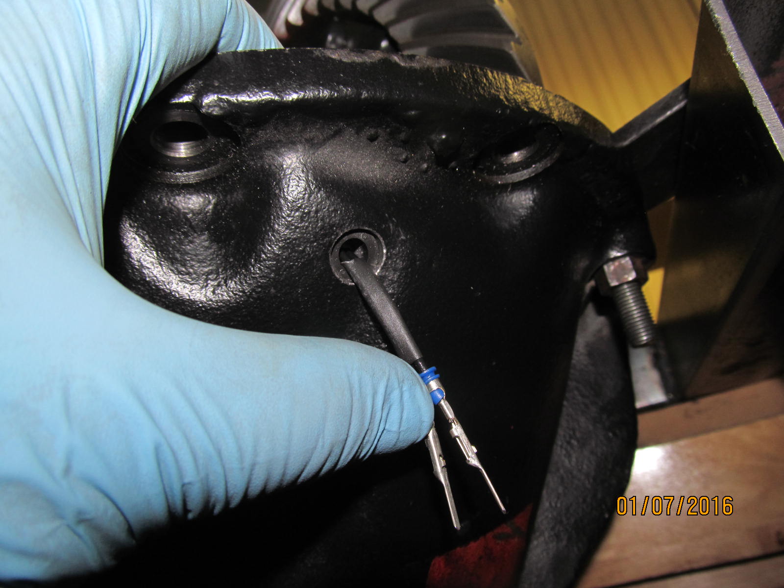
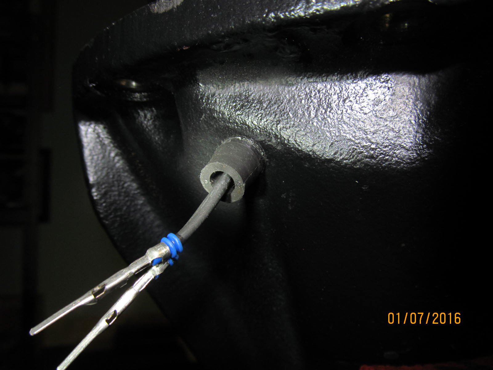
Now the rubber grommet will be pulled all the way thru....just not right now.
|
|
|
|
I found an easy way to get the bracket in....install bracket first like shown into the 2 tabs THEN slide
the bearing cap into place.
|
|
|
|
Drop the 2 long bolts in place. Snug the bolts down and make sure the threads are "in sync" as
shown in the pic below.
|
|
|
|
|
.............................
|
|
|
|
|
The adjusting wheel should start pretty easy.
|
|
|
|
|
The other side is business as usual. The wheel is threaded FIRST then the cap is dropped in place.
|
|
|
|
|
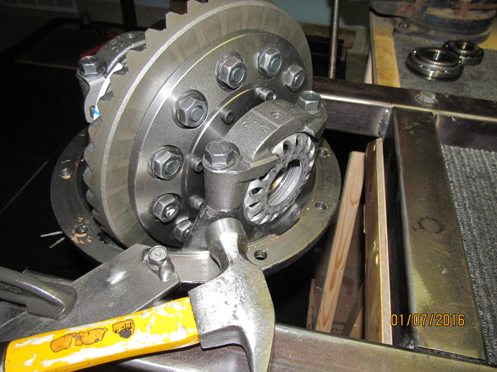
Use the handle side of the hammer and if it goes down with a nice, solid snap noise then all is good.
|
|
|
|
|
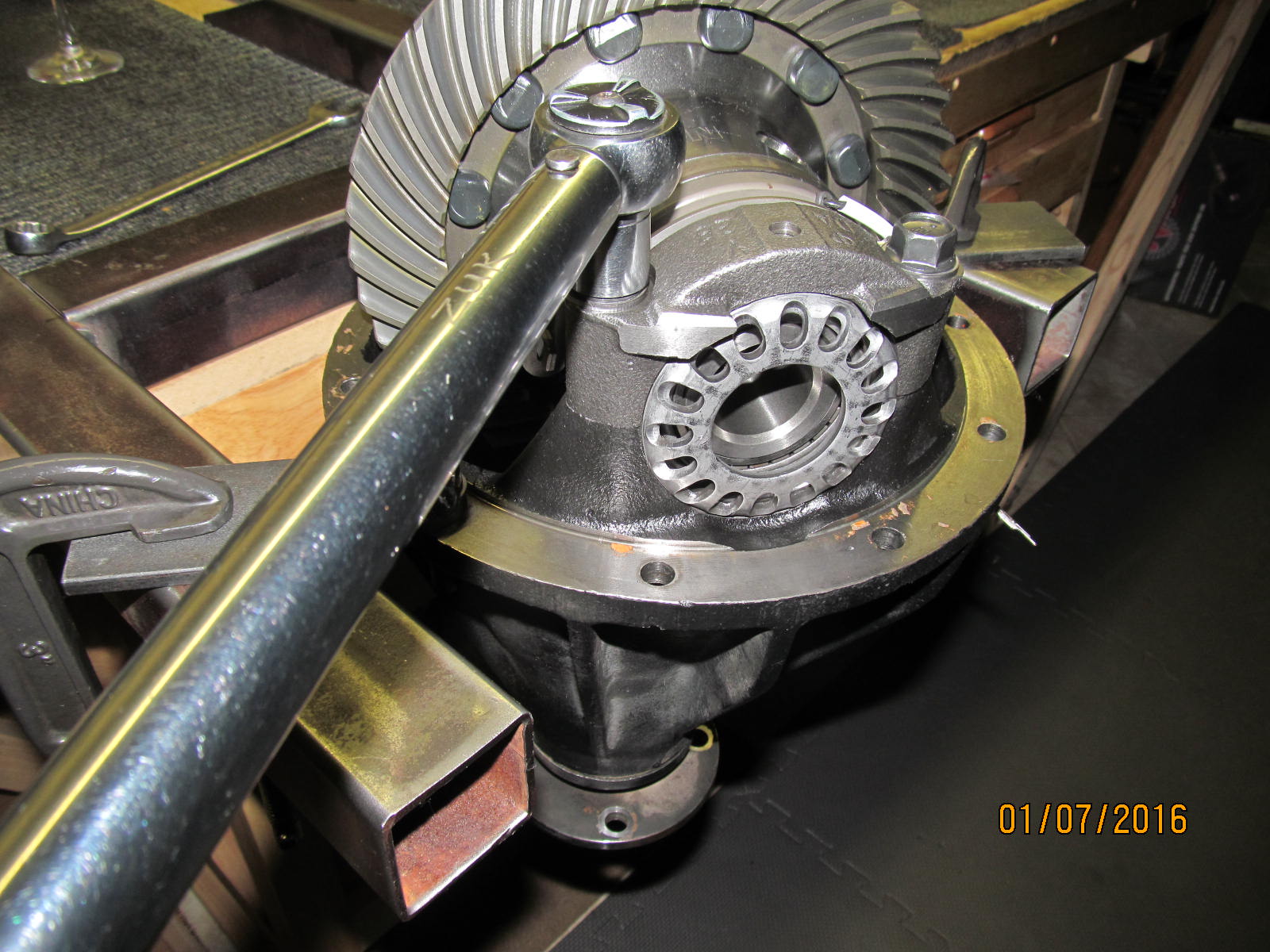
Both of the adjuster wheels turn smoothly with just finger power.
|
|
|
|
|
83 ft/lb on the 4 bolts per the factory repair manual.
|
|
|
|
|
The play of those tabs is verified as good.
|
|
|
|
Backlash and carrier bearing preload are both guided into the desired region. Turn the pinion
and sharp whacks in the 4 regions to equalize bearing tensions.
|
|
|
|
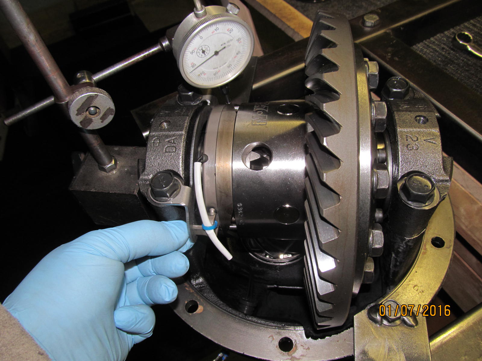
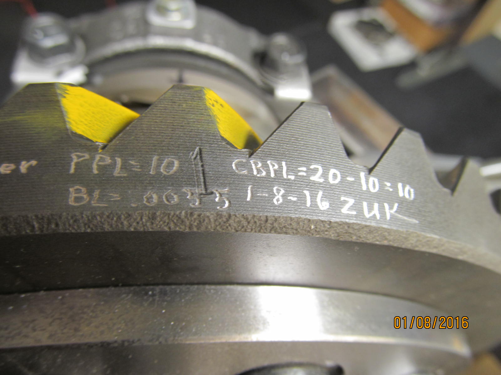
While laying on my back, I can measure the total preload of turning both the pinion bearings
and carrier bearings.....I measured a start torque of about 20 in/lb. I already measured
the pinion pre-load (PPL) before and it was 10......this means the other 10 must be
the carrier bearing pre-load (CBPL).
|
|
|
|
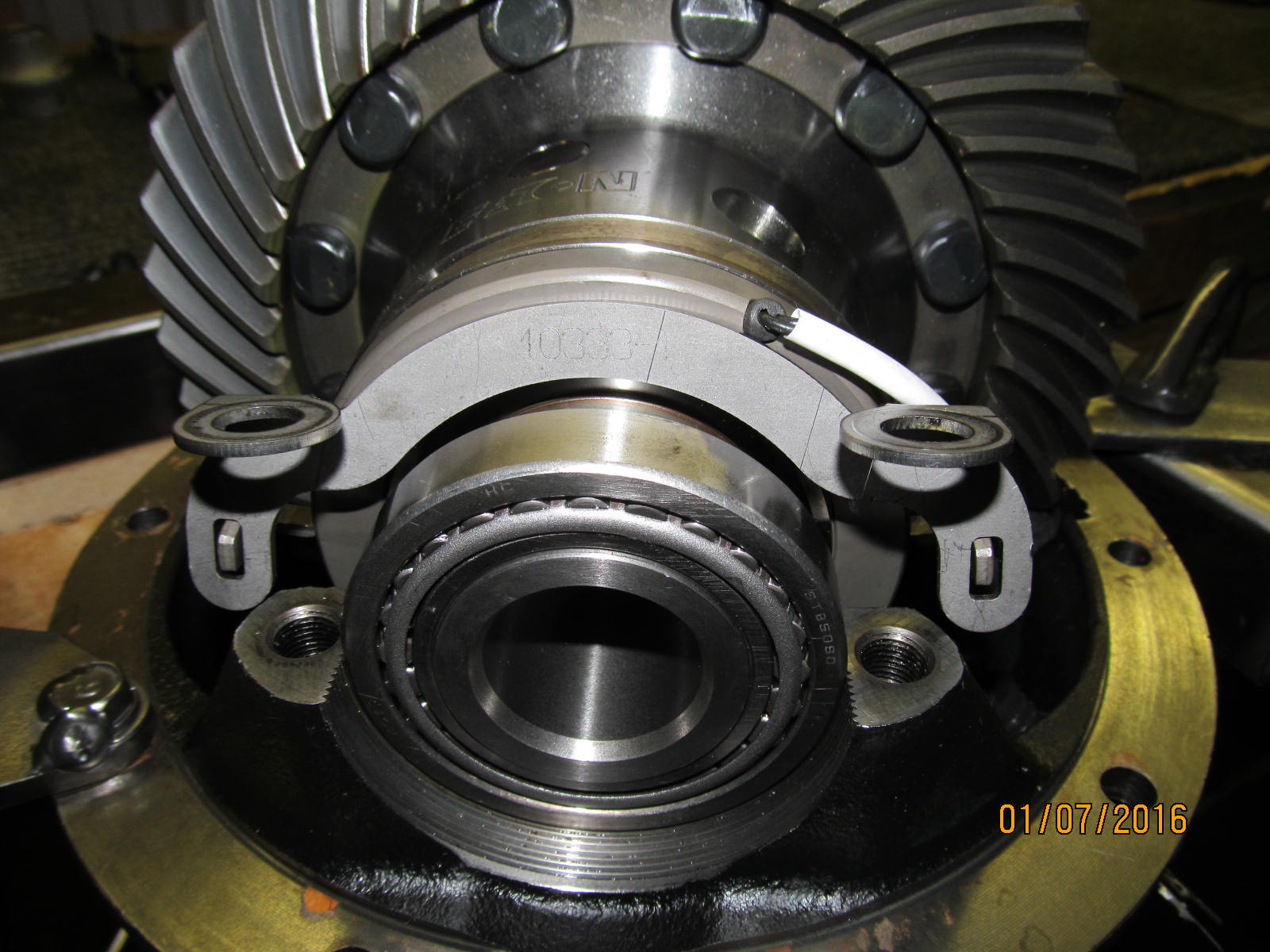
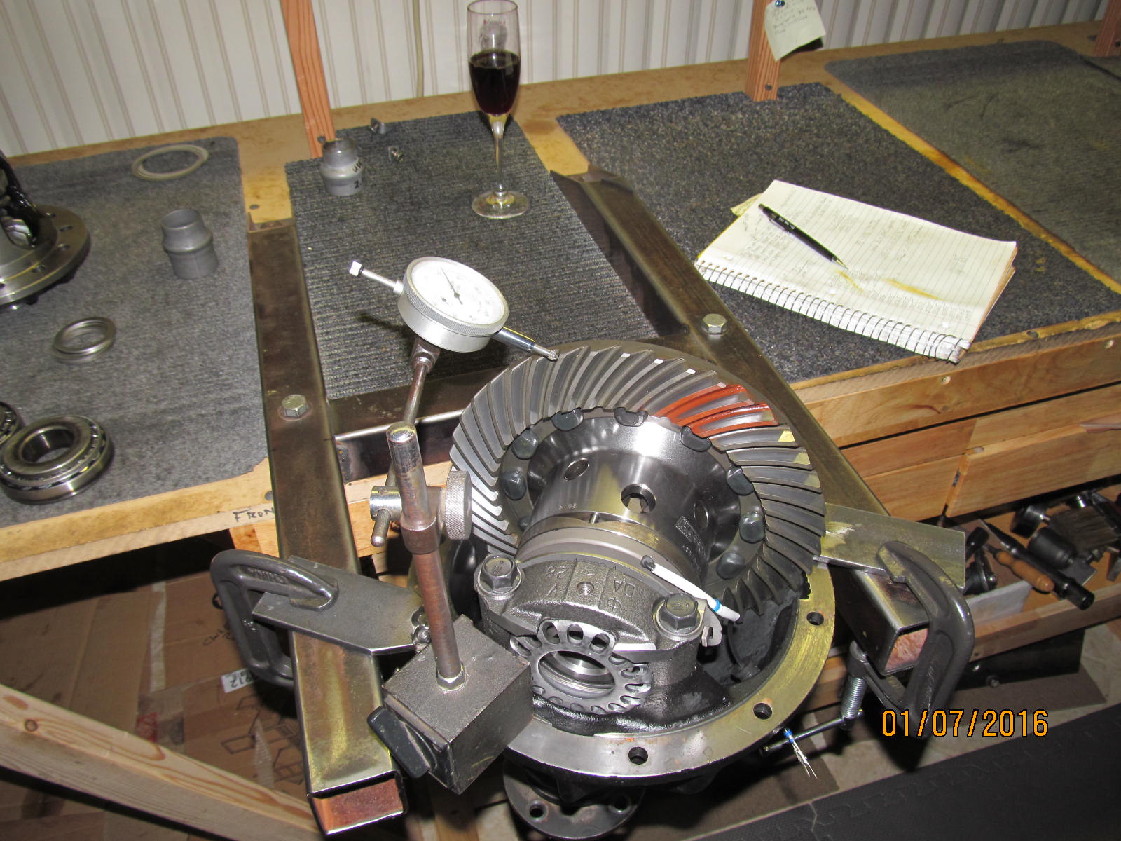
Backlash is checked on every other tooth here and recorded. Looking in the diff, you can see that
I still have to pull the rubber grommet thru.
|
|
|
|
|
Takes a little work to coax that grommet thru.
|
|
|
|
|
Push really hard and sometimes cheat a little with the smooth end of a screwdriver....and it does go in 100%.
|
|
|
|
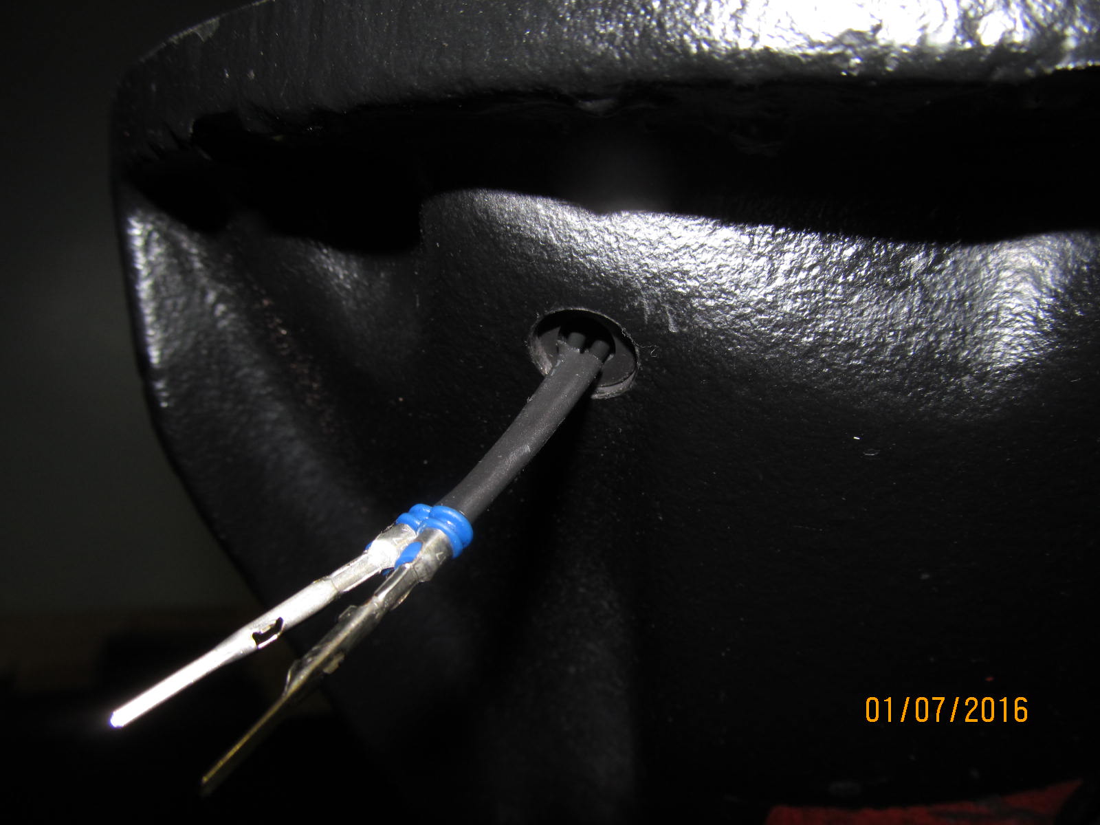
On the outside, there will be about 1/4" sticking out. It took some work to do it so be prepared....
and try not to tear the rubber.
|
|
|
|
|
On the 2 lockdown tab bolts, 10 ft/lb and maybe a touch more.
|
|
|
|
|
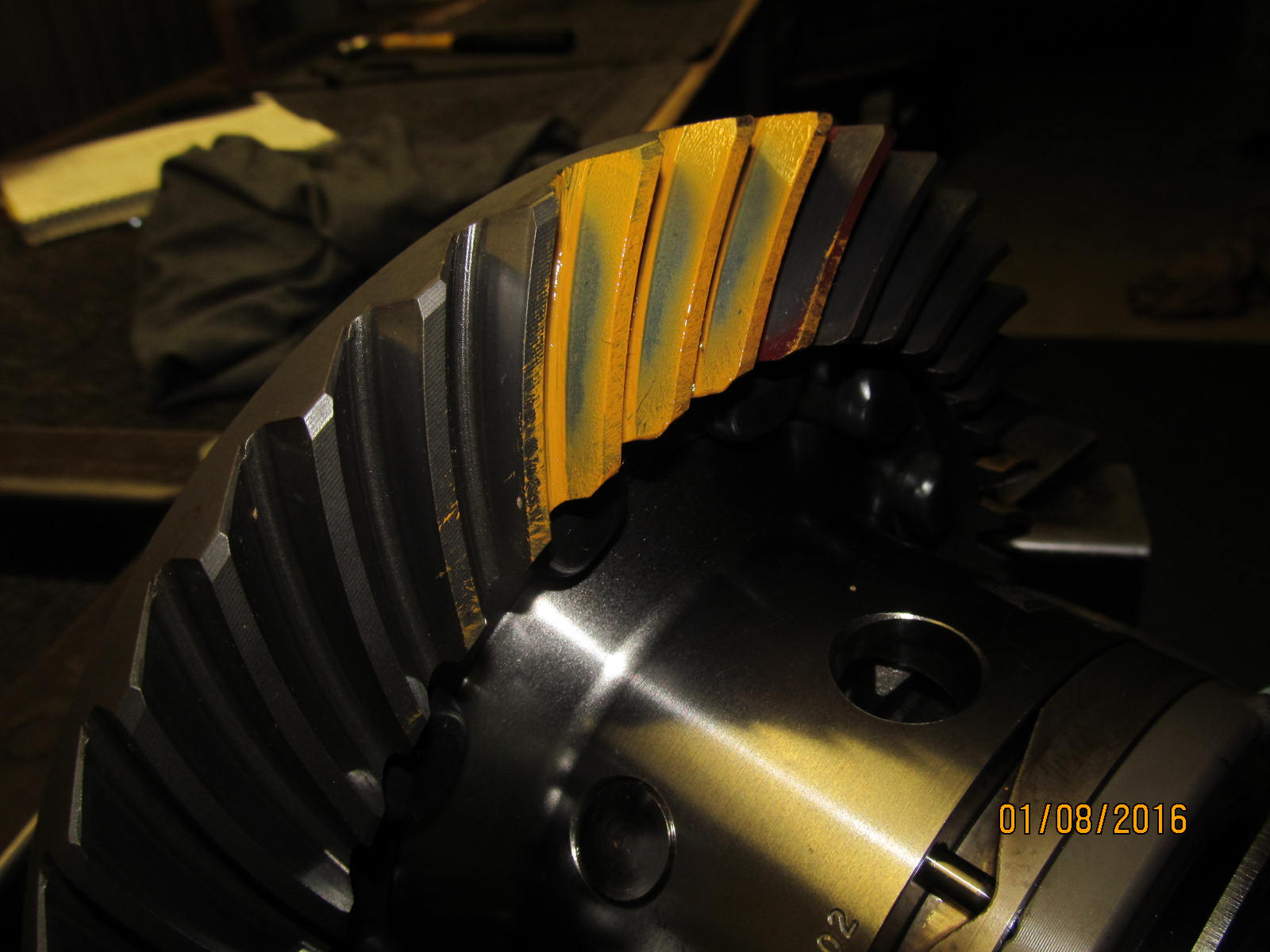
Nice drive pattern
|
|
|
|
|
Excellent coast.
|
|
|
|
|
Drive....reverse painted.
|
|
|

|
Now to test the electric locker. Place axle stub in and it spins the sidegear freely
indicating "open diff" operation.
|
|
|
|
|
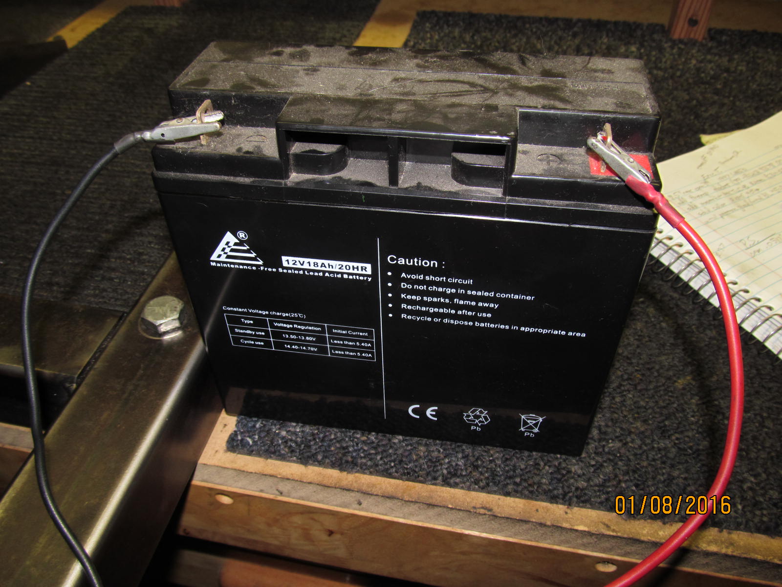
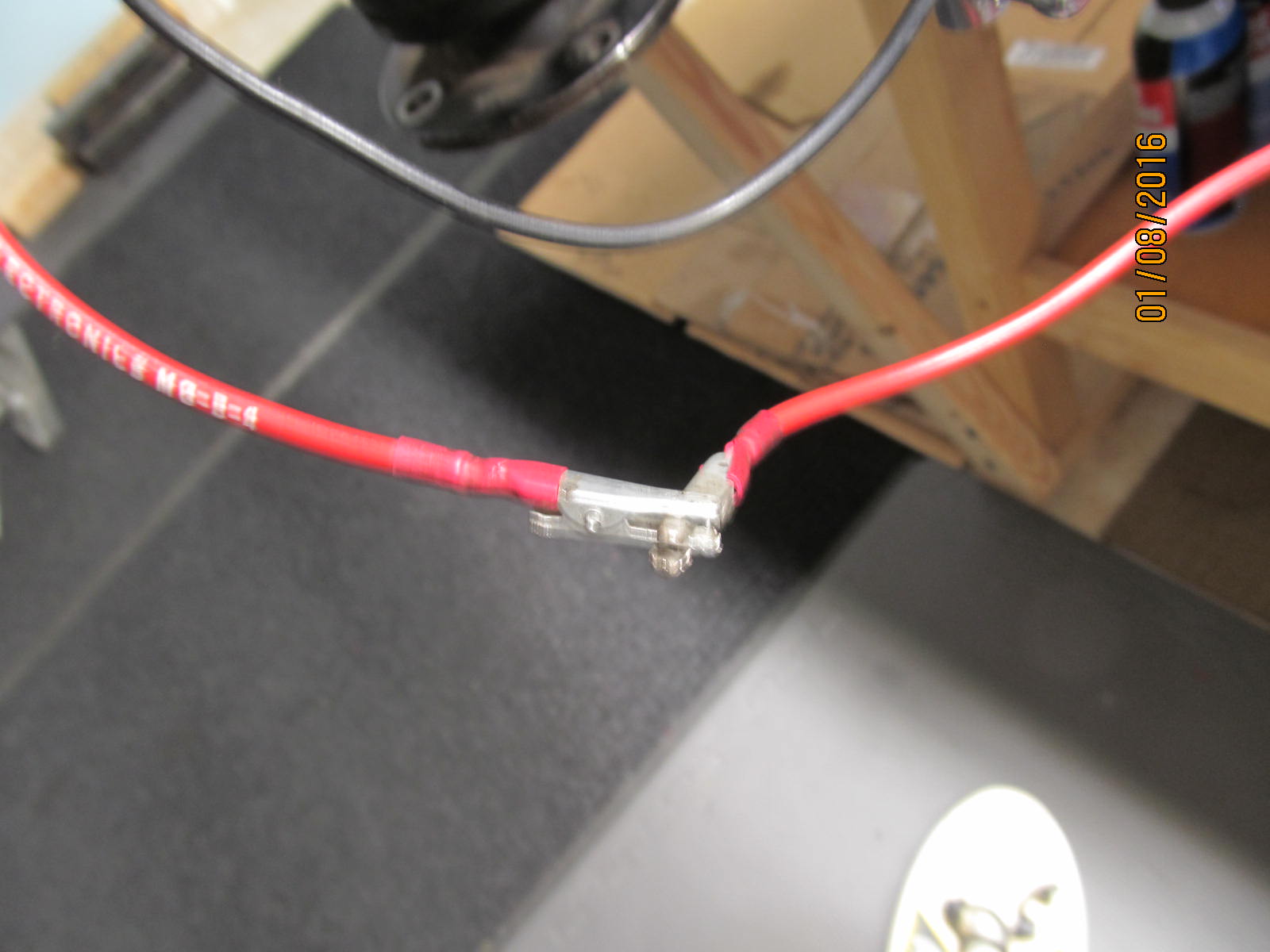
Now to find a source of 12v.....
|
|
|
|
These electric lockers have no polarity so there is no hooking them up backwards and smoking
something....Just hook them up and it will work.
|
|
|
|
|
....
|
|
|
|
|
....
|
|
|
|
|
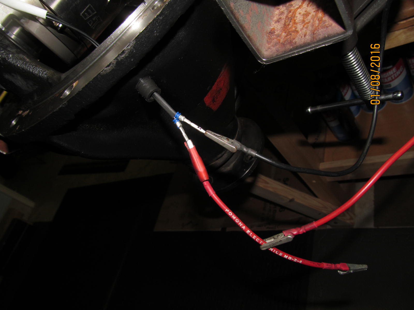
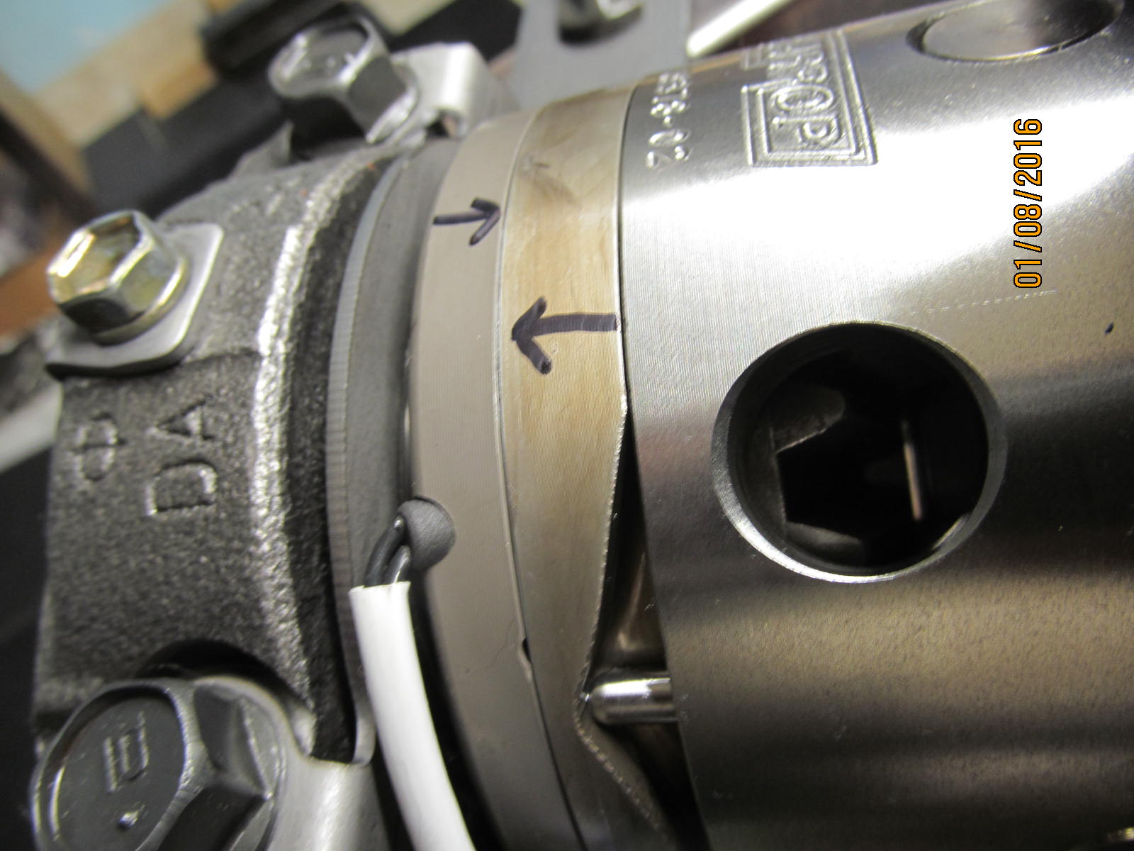
I applied 12v....
|
|
|
|
|
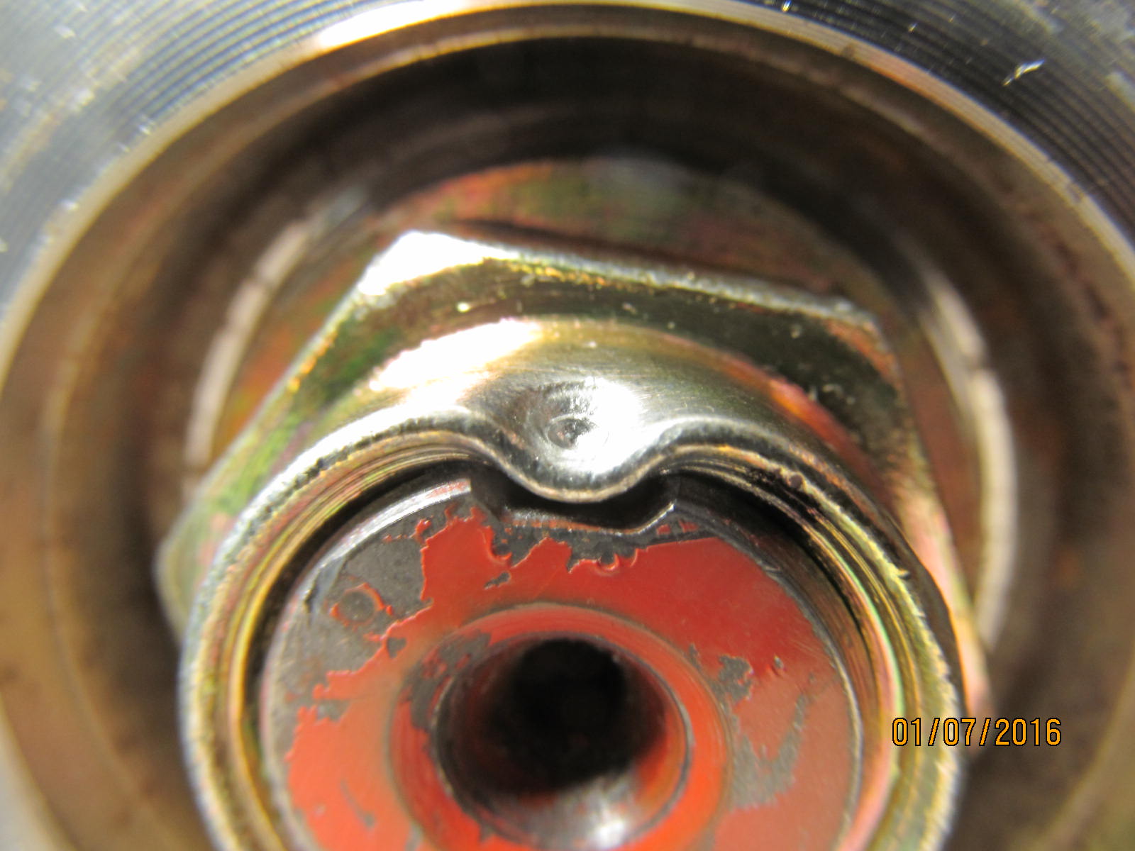
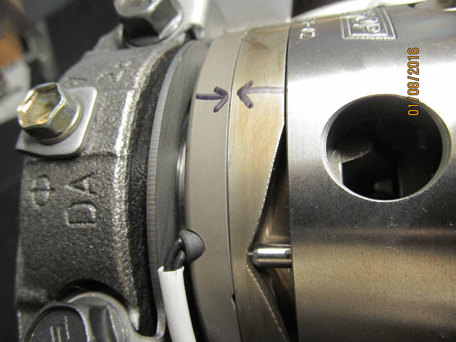
As the ring gear is rotated, the pin was now allowed to retract as shown above.
|
|
|
|
|
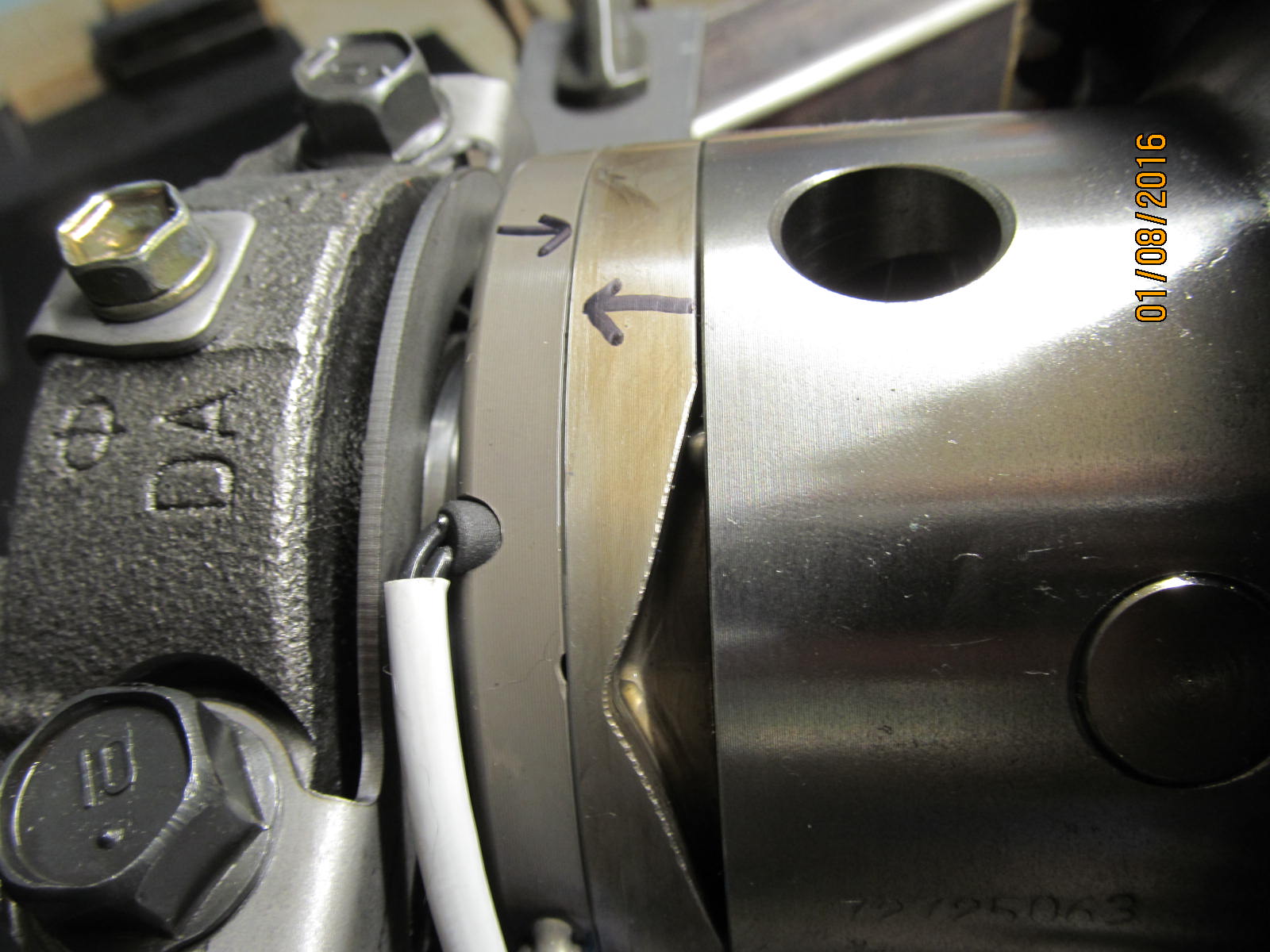
The locker is now locked.
|
|
|
|
|
Remove the 12v and the pin snapped back into place.
|
|
|
|
|
...................
|
|
|
|
|
....................
|
|
|
|
|
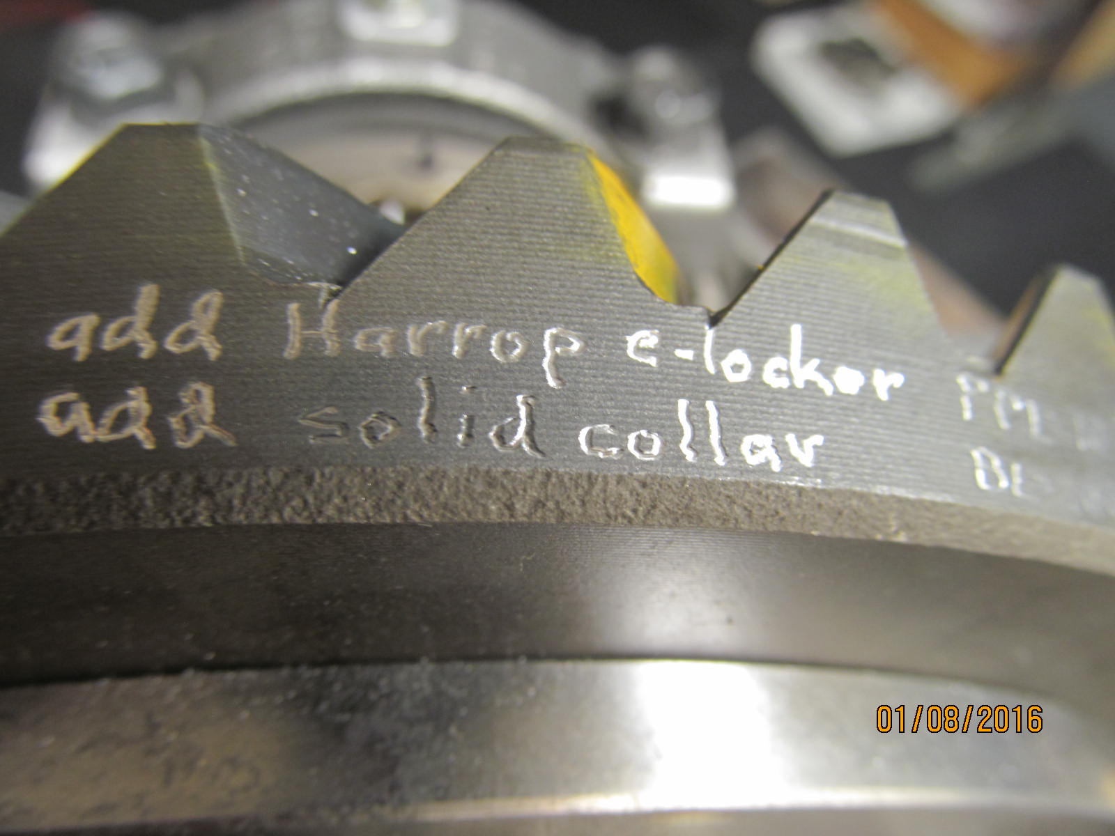
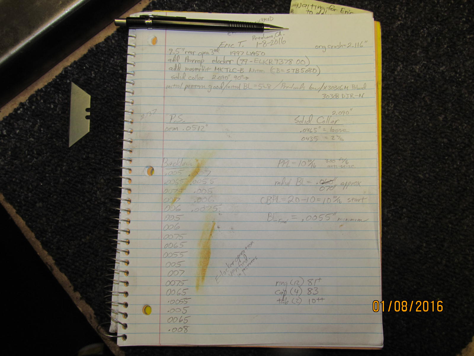
Notes taken for Erics' records...
|
|
|
|
|
Packing it back up for the trip to CA.
|
|
|
|
|
.....
|
|
|
|
Who else wants one of these Harrops installed?
Koyo carrier bearings are already included in the box.
Contact Ward Harris (National importer/authorized dealer for Harrop) at 1-800-224-7801
or email info@cruiserbrothers.com
|
|
|

|