|
|
|
|
|
|
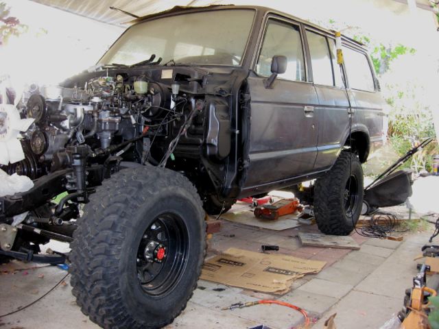
Alf Hayes, out of California, has a 1985 FJ60 work in progress. |
|
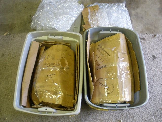
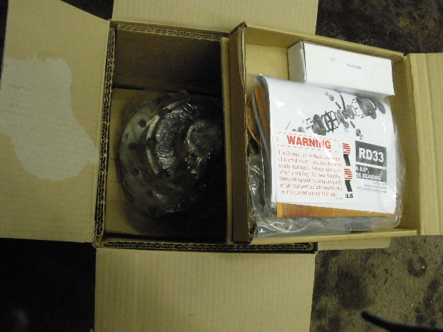
I received two 9.5" 3rds that were well boxed. Burrito wrapping them like this prevents the 3rds from punching through the plastic tote. |
|
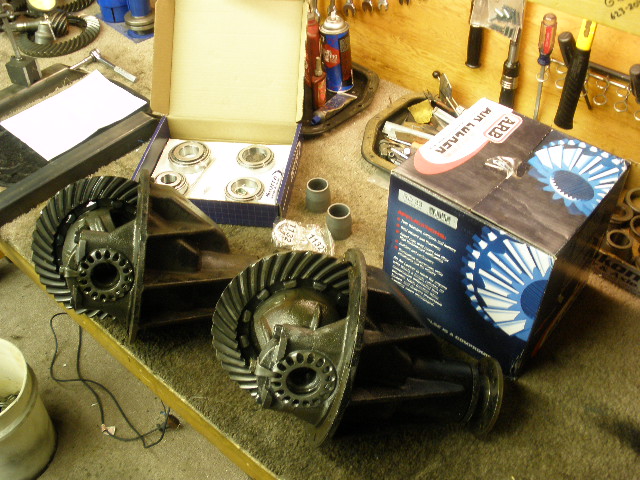
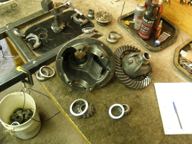
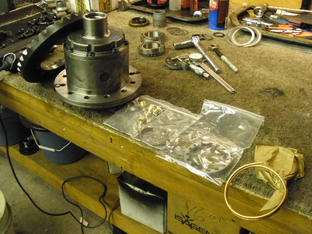
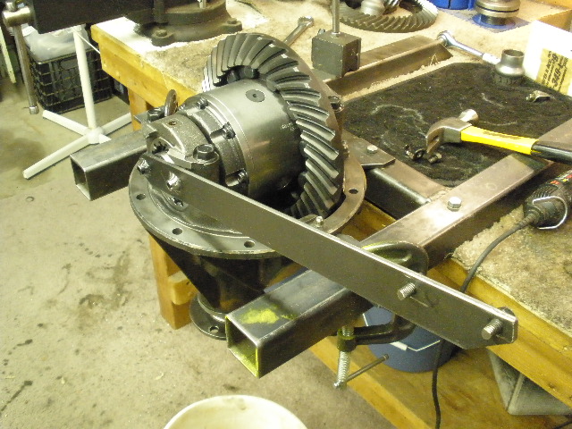
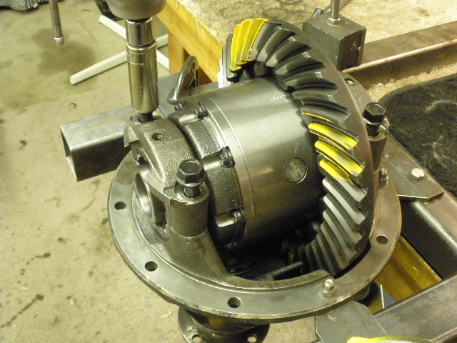
Both 3rds are shown on the bench but this link will only concern the rear 3rd with the RD33 ARB and solid collar. The factory 4.11 gears are to be re-used. |
|
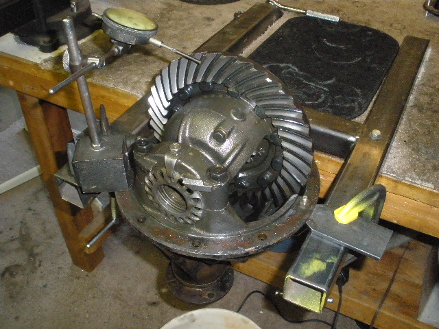
I was going to take a BL check and run a pattern but discovered that the pinion was so sloppy that the readings would be meaningless. |
|
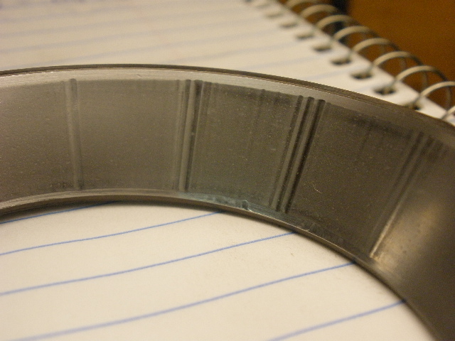
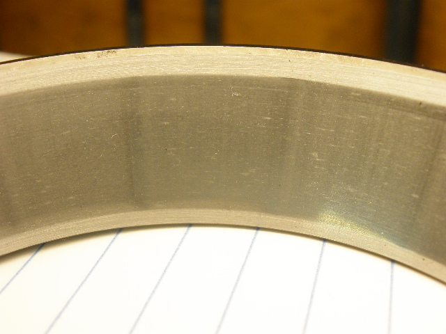
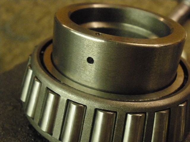
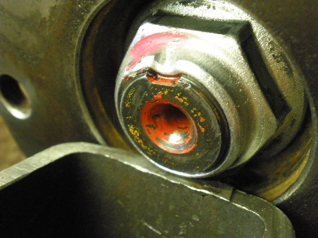
This is a close-up of one of the carrier bearing races....lots of pitting...as well as a wear groove near the bottom. |
|
........................................ |
|
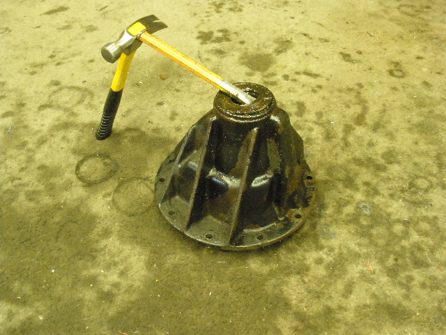
Now to tear into the top end and see what the pinion bearings look like... |
|
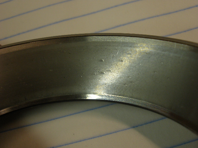
Outer pinion bearing....badly hammered. Those a deep vertical grooves from the rollers. |
|
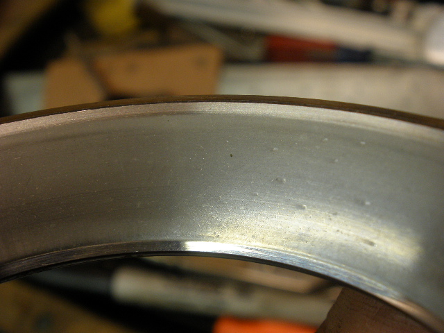
Even the much larger inner pinion race is history.....pitting and some vertical denting. |
|
Items are dis-assembled, cleaned, and inspected. |
|
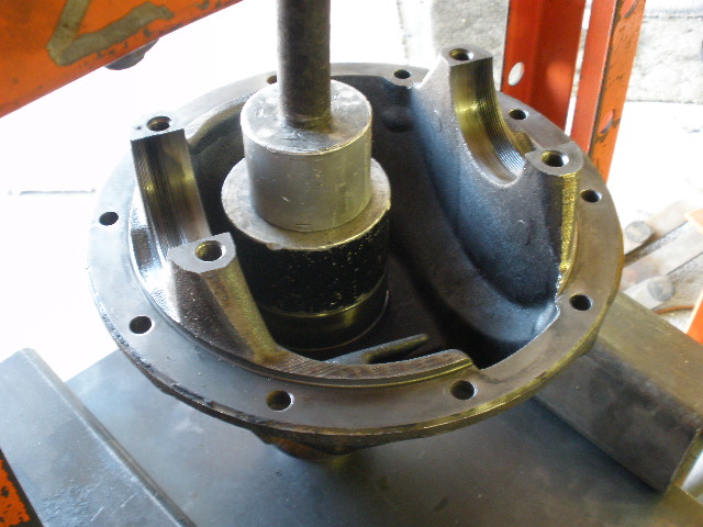
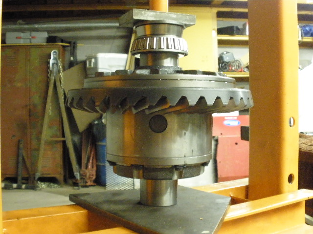
New races are pressed in. |
|
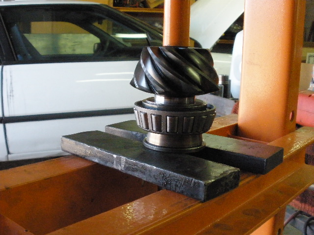
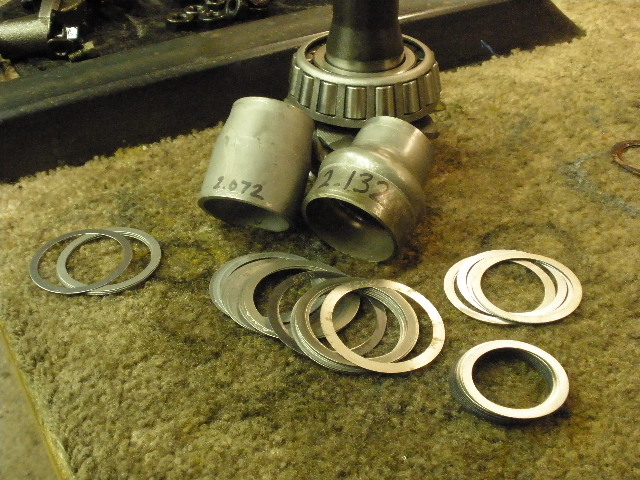
The factory .0475" shim is pressed on with the new bearing. |
|
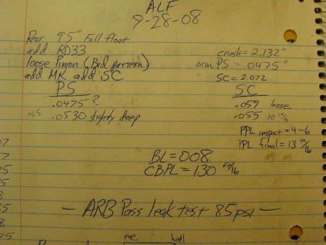
The old crush sleeve is measured against the new solid collar to help determine the shim stack needed. Doing the math, the shim pack will be somewhere's in the .060" area. |
|
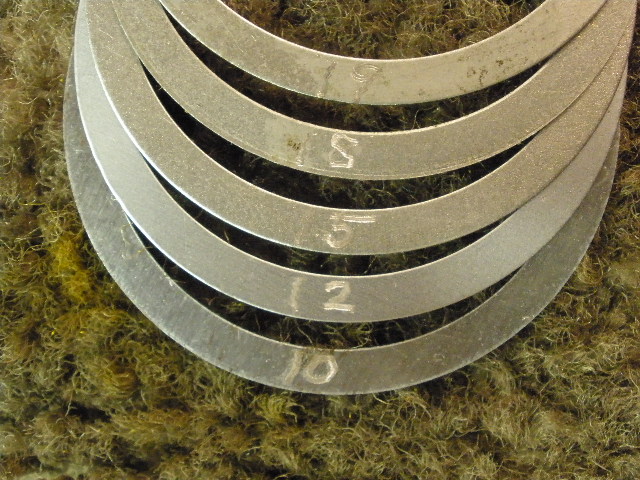
These are the shims that were included with the collar...not exactly a big selection... 010 012 015 018 019" |
|
I assembled it the first time with a stack of .059" and it was too loose (no pre-load). |
|
The second go-around I used .055" and that resulted in an acceptable 10 in/lb. |
|
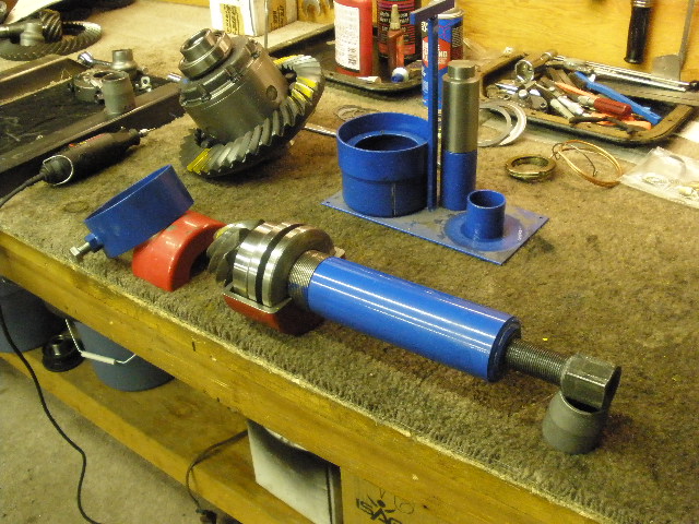
With the pinion end done now I can turn my attention to the ARB end. |
|
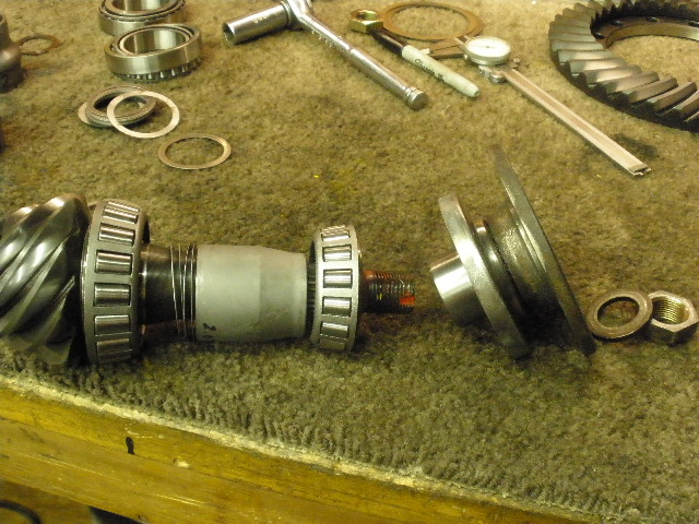
Items are lined up. |
|
The ring gear was a very tight fit onto the case but with some TLC it did go on. |
|
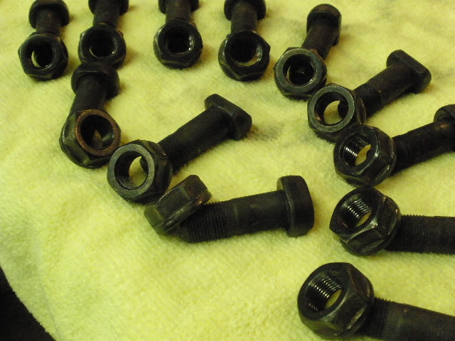
The factory ring bolts and nuts are cleaned. These are very high quality specialty bolts...and very pricey. As far as I know, none of the master kits have these in them. It's perfectly ok to re-use these as long as there's no obvious thread damage. |
|
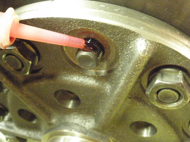
Red Loctite is applied. |
|
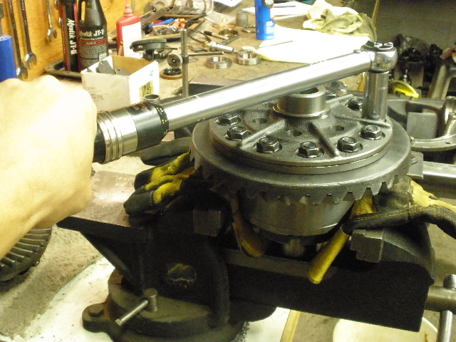
93 ft/lbs is the tightening torque. |
|
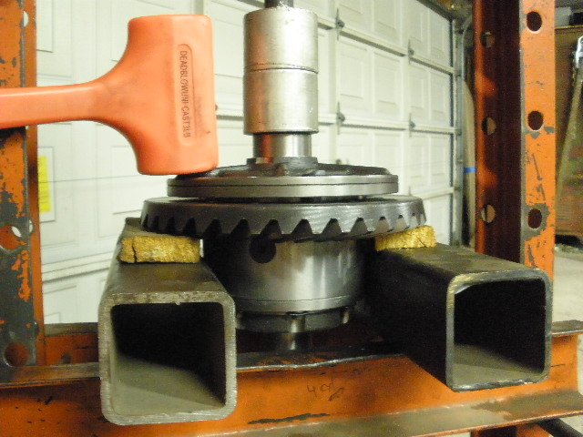
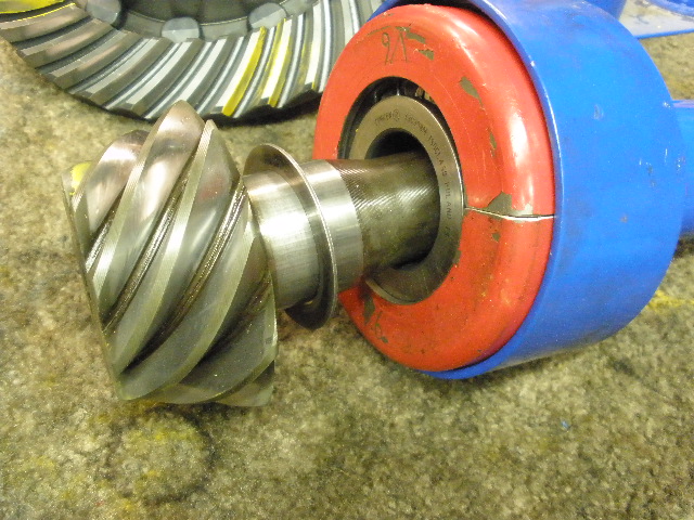
Carrier bearings are pressed on one at a time. |
|
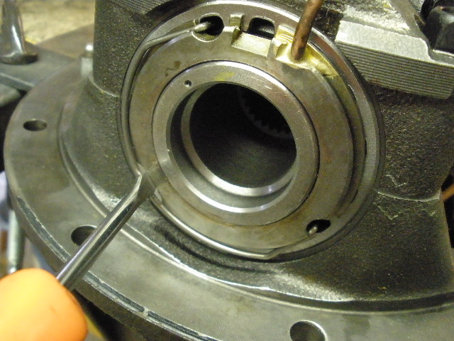
Care must be taken not to scratch or damage this surface as this is where the 2 o-rings ride. |
|
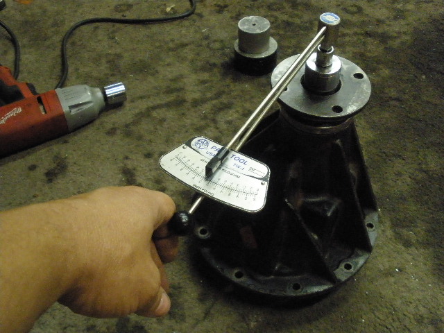
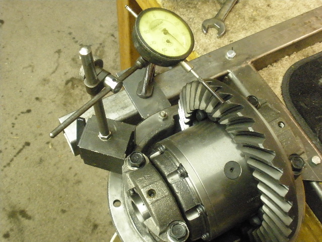
The wheel adjusters are tightened such that there is some CBPL... |
|
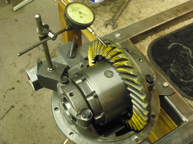
...and the BL is near .008" using a dial indicator with magnetic base. |
|
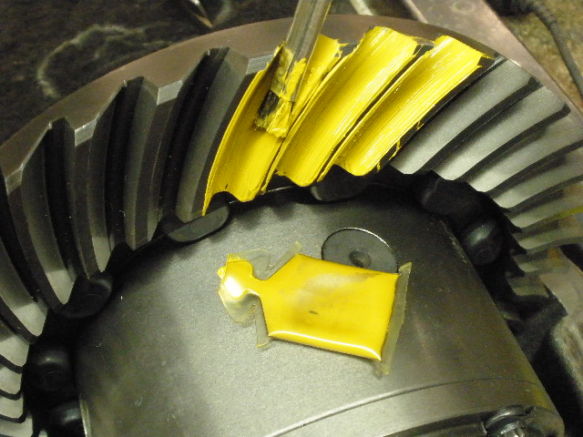
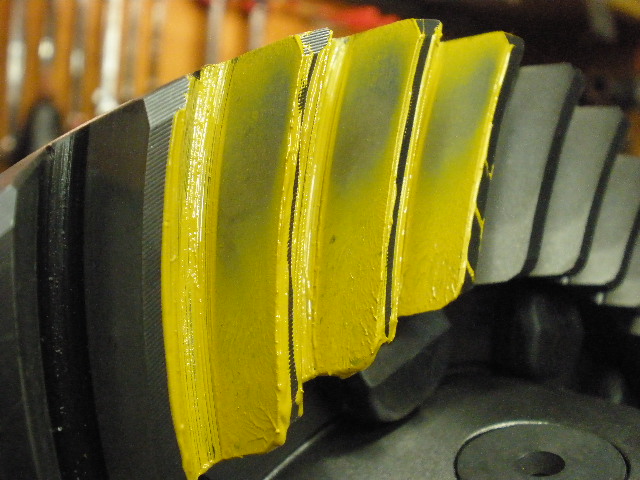
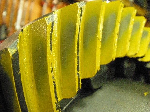
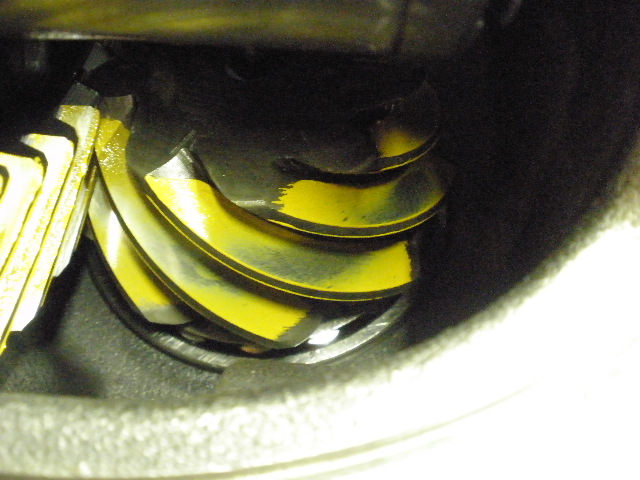
Yellow marking paint is applied to 3 of the teeth on both drive and coast sides. |
|
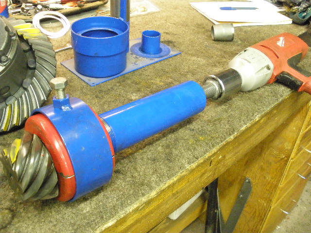
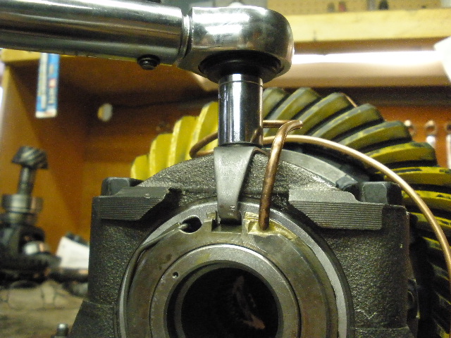
A 19mm wrench is then turned back and forth while some minor resistance is applied to the pinion flange with a rag. |
|
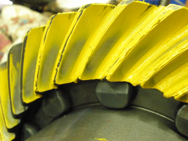
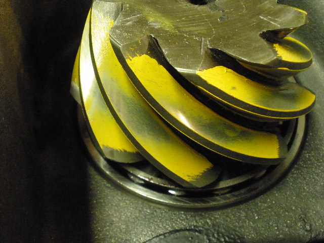
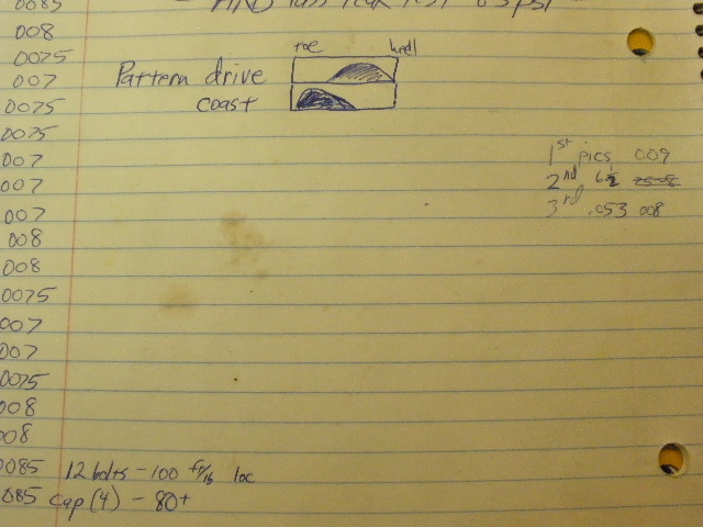
The result is an easy to read pattern. This drive pattern favors the heel end....I'd like to see it closer to center. |
|
Coast is heavy on the toe end...tighter BL will help both conditions but I can't see going any tighter than .008"... a thicker shim will have a positive influence on both conditions and I will do that. |
|
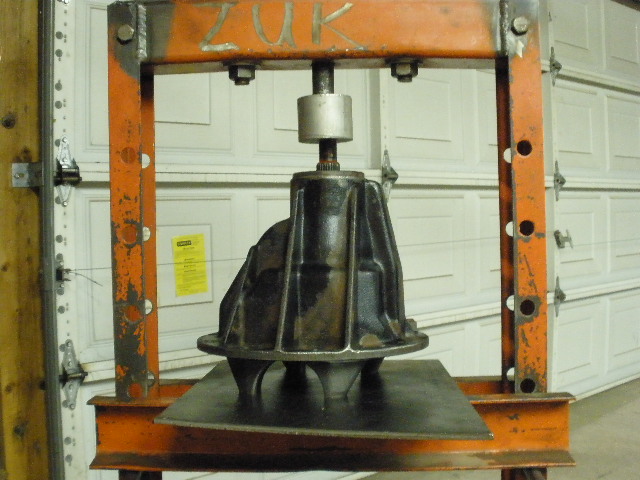
So, that means the case comes back out... |
|
...the pinion flange comes back off... |
|
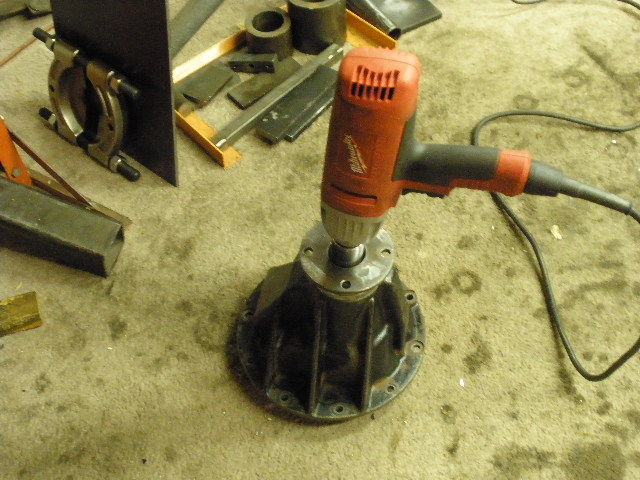
...push the pinion out... |
|
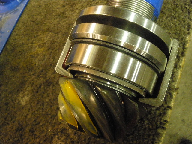
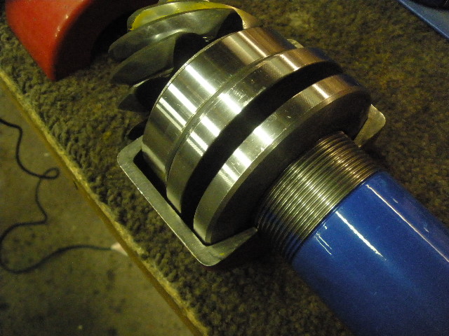
...remove the pinion bearing. The bearing separator would not clearance in the small gap between the pinion teeth and cage so this deluxe puller was brought out. |
|
... |
|
... |
|
... |
|
It's a $400 puller but it's either that or waste the expensive pinion bearing. |
|
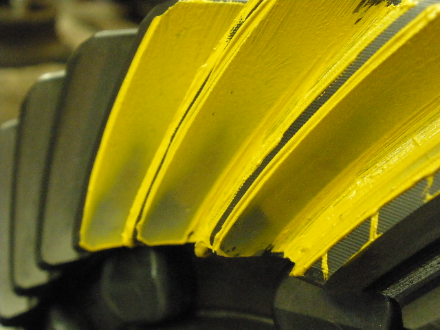
This is going from the factory .0475" shim to a .053" shim.....0055" deeper. This is an improvement. |
|
Coast has a better spread towards the center also. |
|
................................... |
|
The pinion pattern is in agreement also. |
|
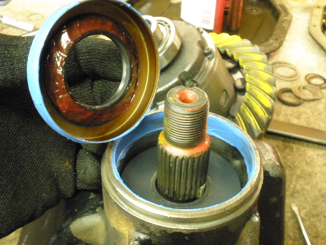
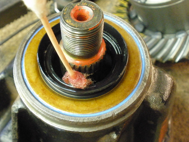
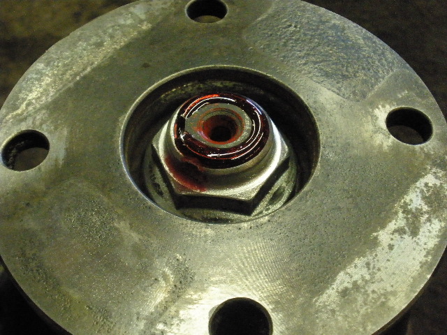
Satified, now I can install the seal. Grease is applied to the inside to prevent the tiny coil spring from popping off. Ultra-Blue RTV is applied to the outside to allow it to tap on easier and seal better. |
|
Gear oil is applied to the rubber seal surface to prevent a dry start-up. |
|
Red Loctite is applied to the threads and the electric impact tightens the nut to well over 150 ft/lbs. |
|
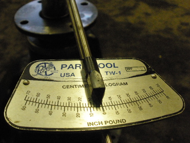
One would expect the same 10 inch/pounds established the first go-around but things can sometimes 'shift' and 4~6 inch/pounds was actually measured this time. |
|
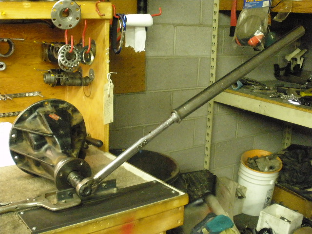
There is quite a bit of flexibility when using a 4 foot cheater bar...PPL can be increased by tightening the nut about 1/8th of a turn.... |
|
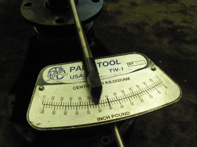
...resulting, in this case, a final PPL of 13 inch/pounds. Perfect. Something had to give almost .001" to increase the PPL from 4 to 13...maybe it was a combination of the shims compressing and the solid collar giving a little. Uncertain. |
|
Ding the nut and done on this end. |
|
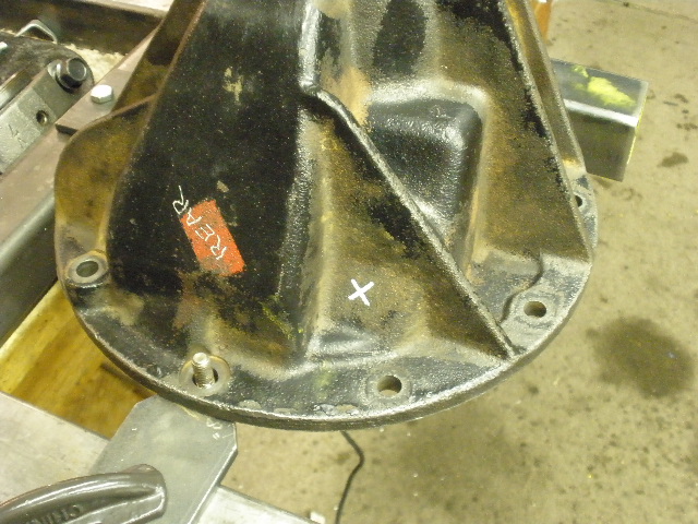
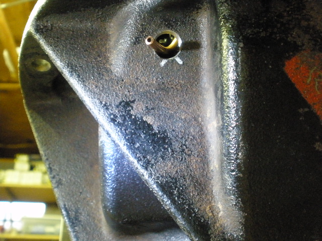
X marks the spot where the 7/16" hole will be drilled. |
|
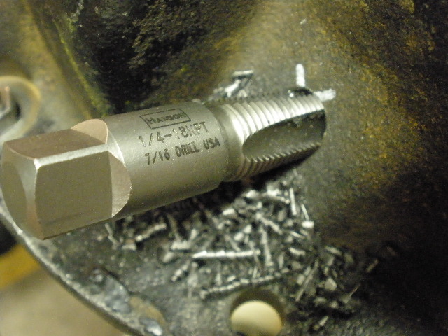
A sharp 1/4 NPT cuts very nicely. |
|
Do not let the tap run too deep as it will open up the hole til it's too big. I stopped the tap operation right about here... |
|
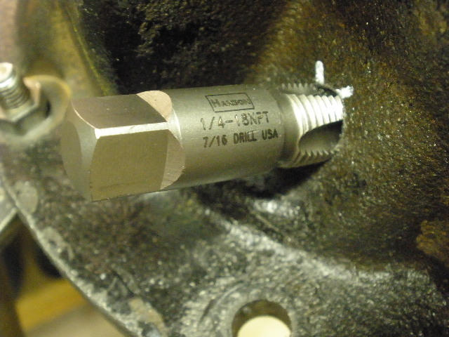
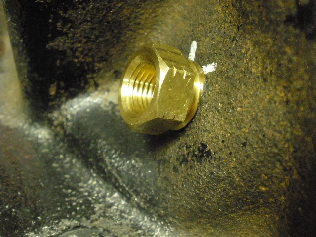
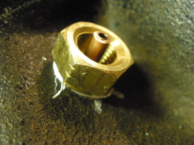
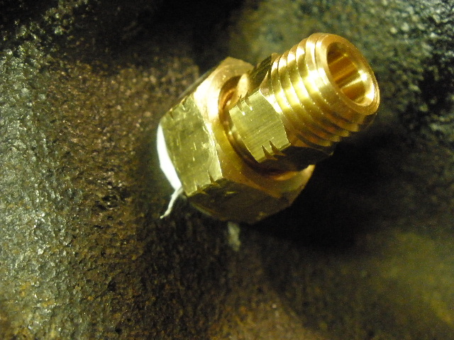
Perfect...the brass bulkhead fitting started to tighten up right about here. |
|
... |
|
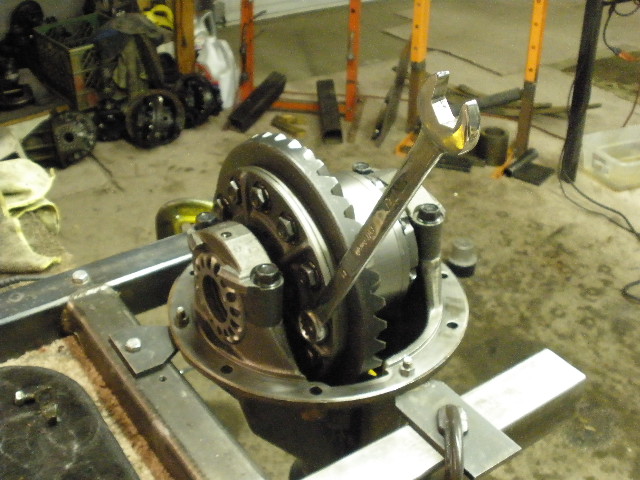
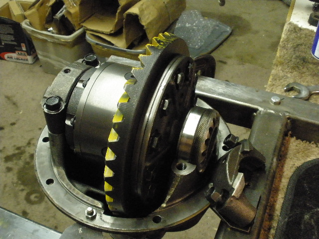
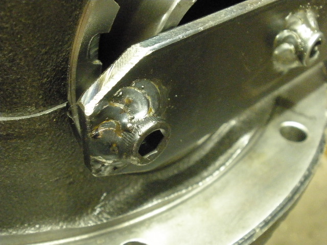
ARB is in place, adjuster wheels are aligned properly, and the bearing caps are bolted in place. |
|
They are tightened with a tool made from scratch. |
|
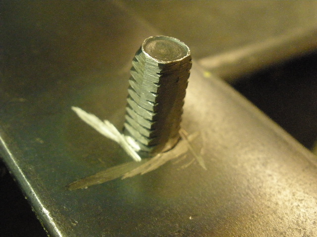
Allen bolts are among the hardest and durable. |
|
... |
|
I even ground down the threads to make it fit perfect in the ARB adjuster wheel notches. |
|
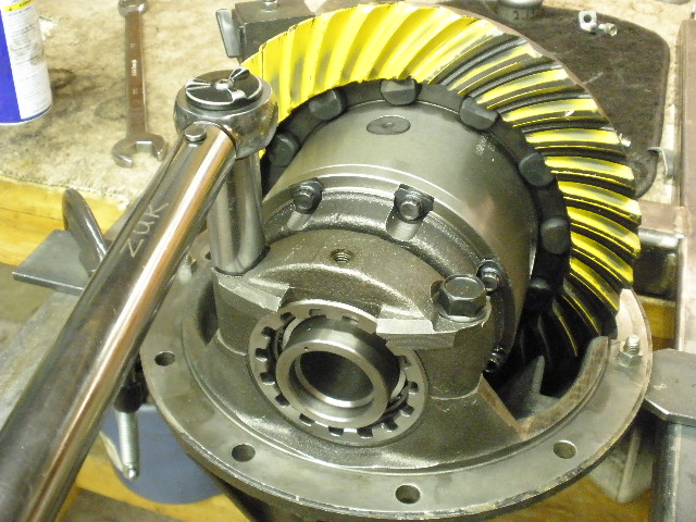
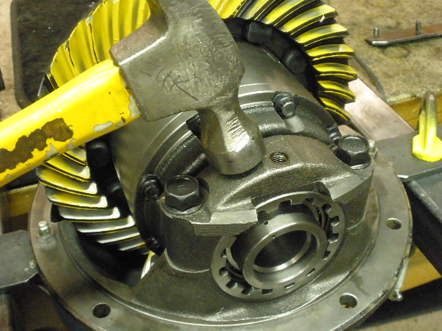
Light taps while turning the ring gear allows the carrier bearings to self center and equalize the tensions between each other. |
|
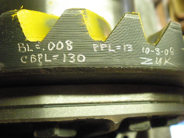
I tightened the wheels in an equal manner (with hammer taps) til the BL reached .008" and the CBPL was 130 ft/lb. |
|
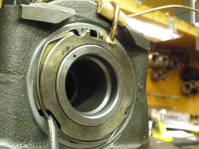
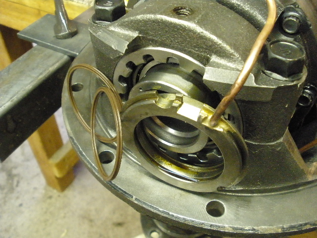
The air bearing assembly is temporarily clipped in place without the special rubber o-rings in place yet. |
|
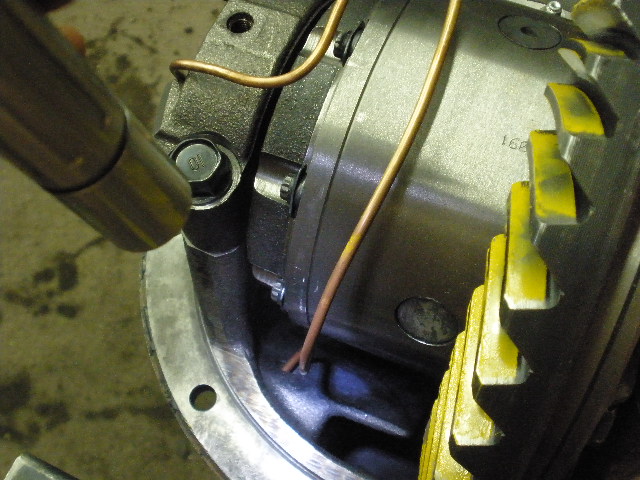
Forming the soft copper tubing can be time consuming, for me at least. |
|
The tubing is cut at the estimated spot. It's a good thing there is plenty of service loop just in case I cut it short. |
|
.......................................................... |
|
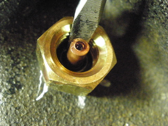
Without the brass bulkhead in place, it's easy to pass the copper through the hole and self center it at my leisure. |
|
The o-rings are now inserted and the air bearing assembly is ready. |
|
Use lots of gear oil on the o-rings and push the air bearing in place and then snap the retainer clip in place. |
|
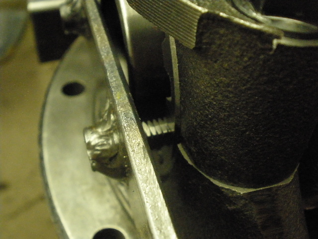
Tighten these to 10 ft/lb. The bottom of these tabs must not touch or press up against the air bearing. |
|
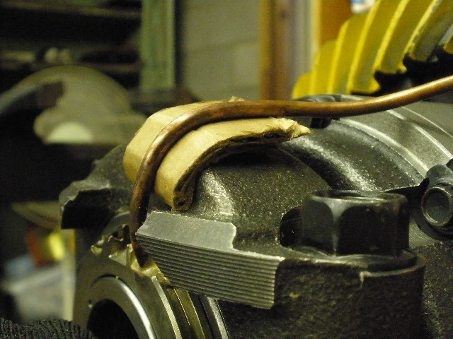
Now is the time to wrap teflon tape on the bulkhead and tighten it down with a 9/16" wrench. |
|
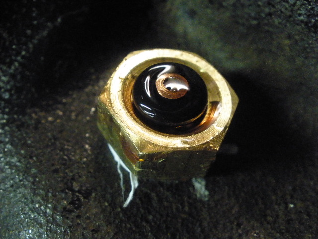
Gear oil on the fat o-ring.... |
|
...and push it in place without cutting the rubber. |
|
Screw the coupler on and it's ready to go. |
|
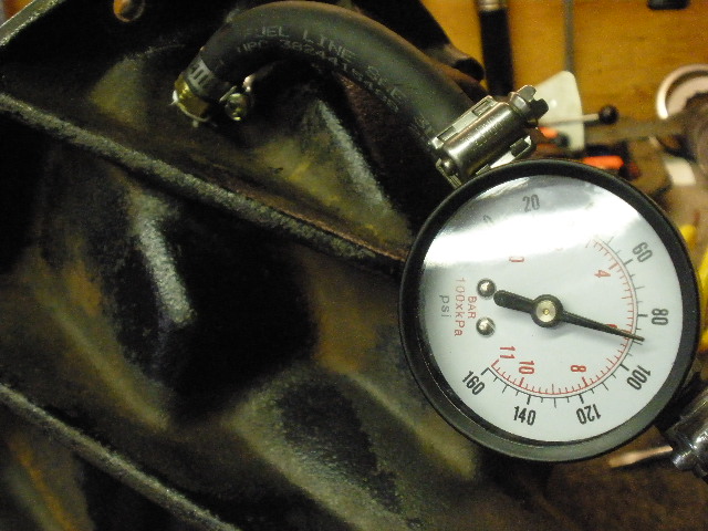
I have a test hose and tested it at about 85 psi and saw no leakdown after 5 minutes. |
|
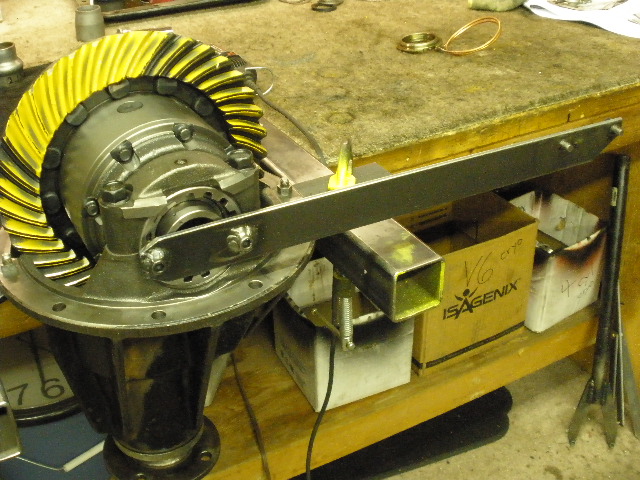
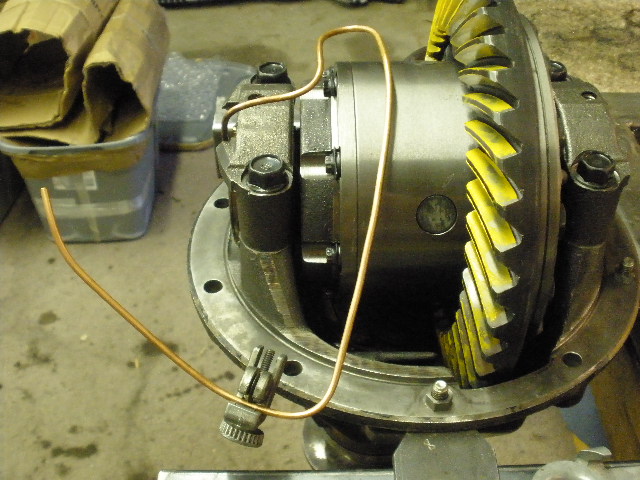
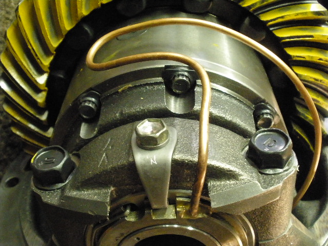
A look at the routing of the copper line. |
|
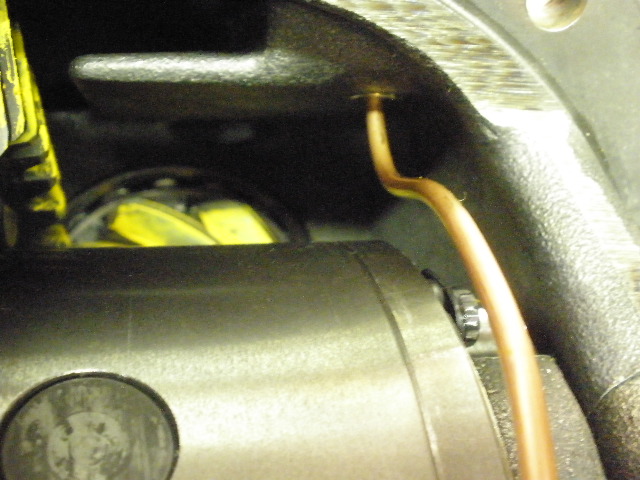
Everything is clear by 1/4". |
|
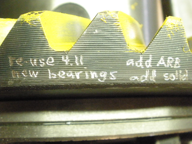
Every ring gear gets some sort of documentation like this. |
|
... |
|
... |
|
ZUK |

|