Genuine Gears went KABOOM, John upgrades to 29 spline Nitro Gear Install
(116 good size pics loading....may take a minute to see all pics)
MARCH 16 2013

John's 1985 Toyota 4Runner has a 22RE 5-speed, 37 12.5 15
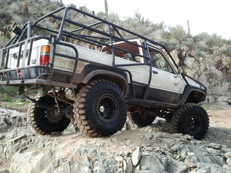
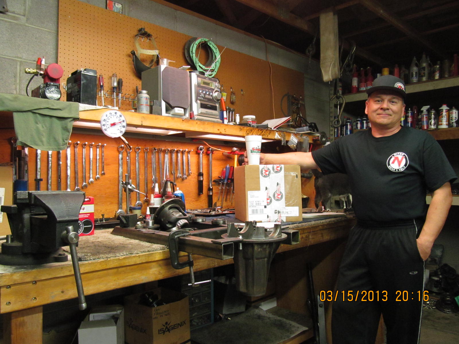
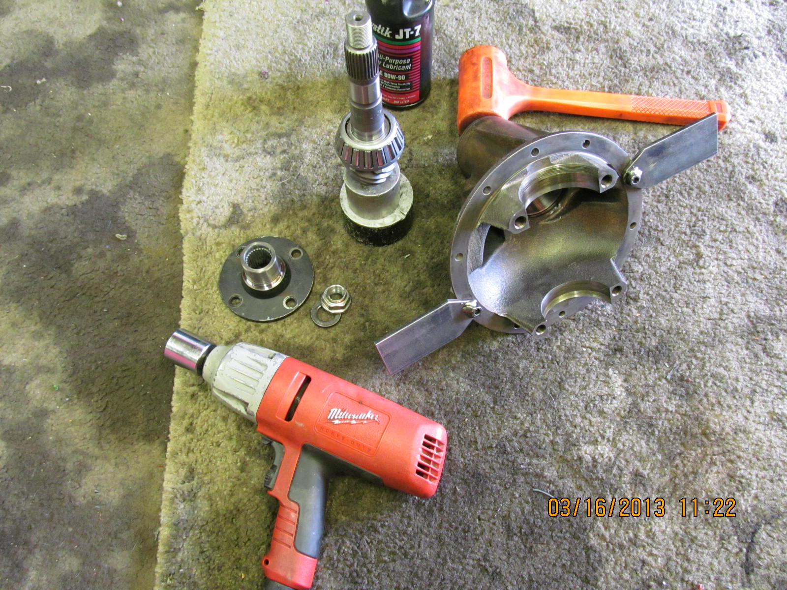
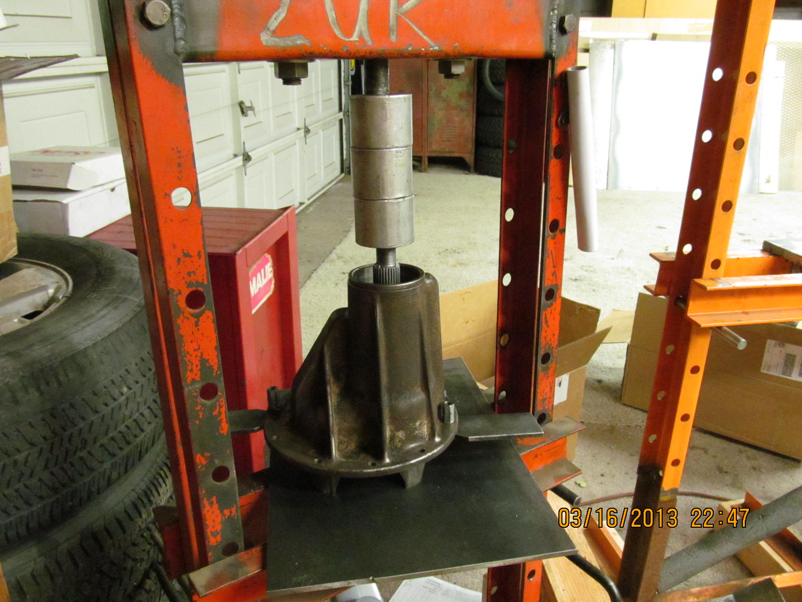
Creepy Crawlers, steel beadlock wheels(heavy), Longfield axles,
chromo hub gears, dual t-cases, full-bodied rig plus lots
of extra weight in exo tube work, winch, full size spare,
tools, spare parts and fluids. John carries a lot of tools
and spares on the trail. It's a weekend crawler that gets
trailered about 70% of the time. It's seen Sledgehammer,
Pritchett, Green Day, and a whole slew of others.

This carnage happened on a Colorado trail called "Carnage".

....

....

These are the cheap econo Genuine Gears and these are the ring
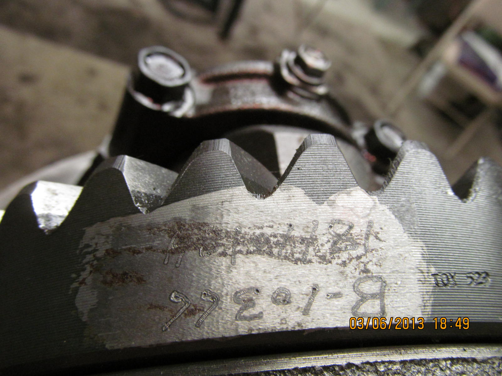
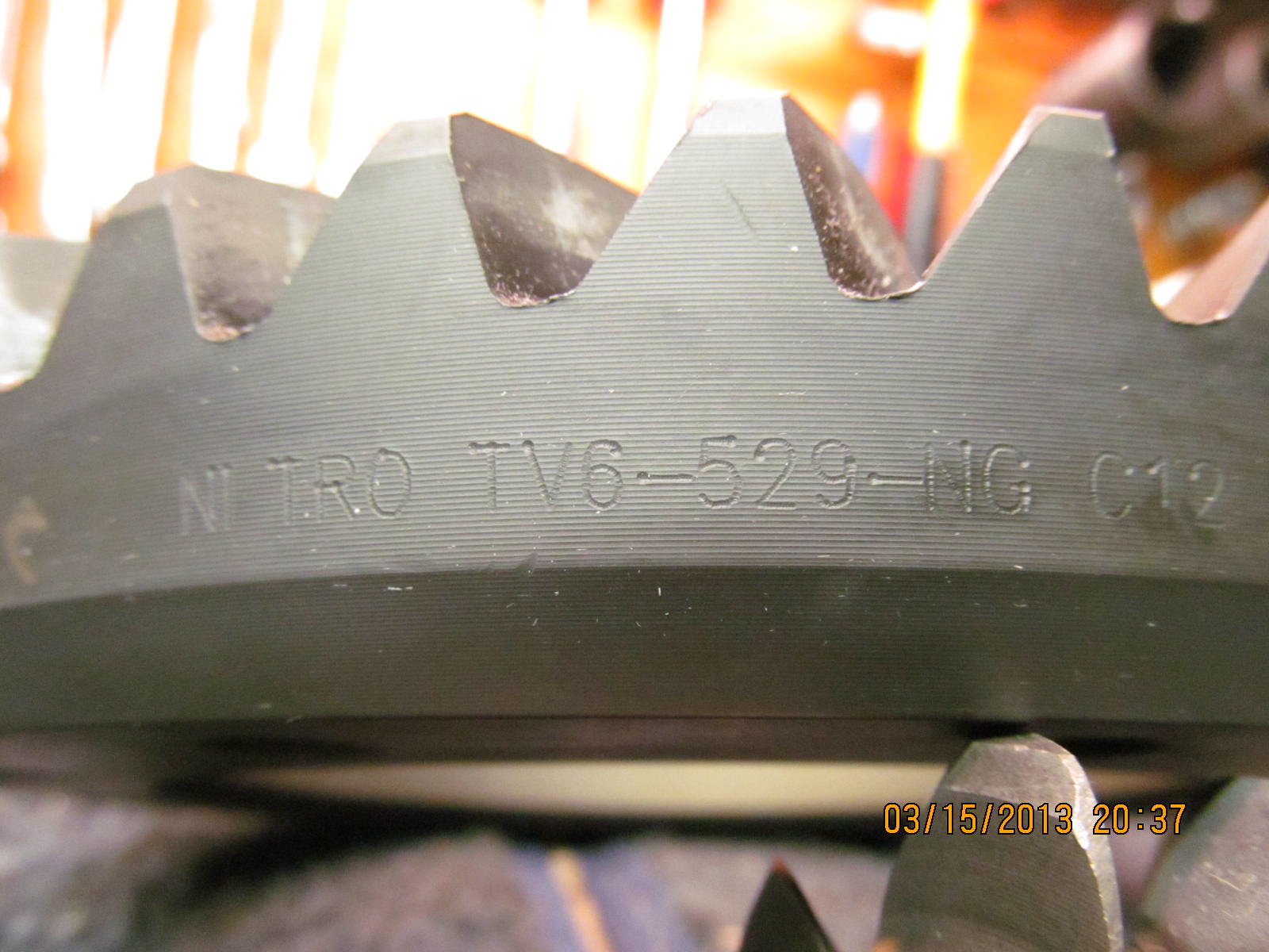
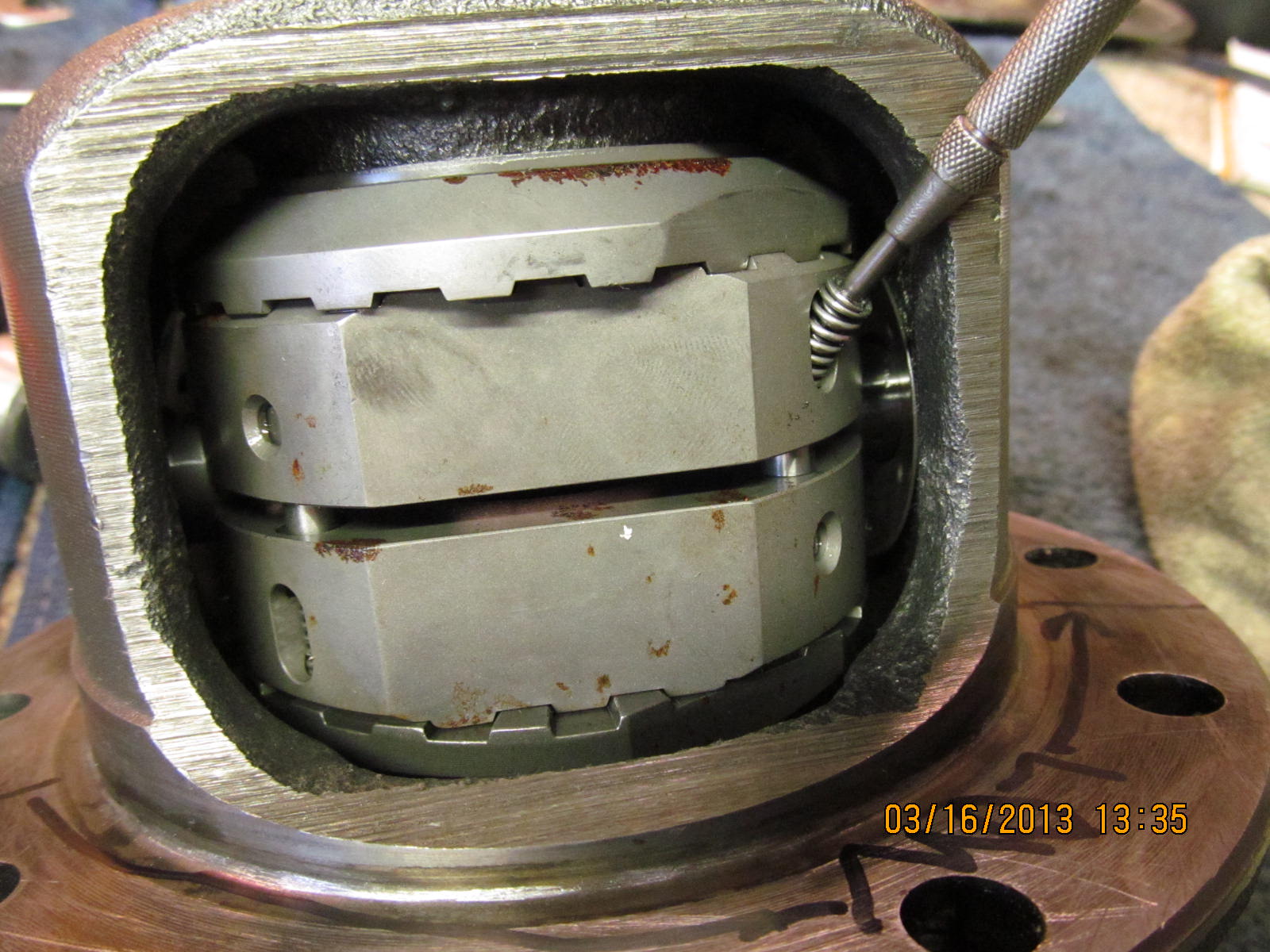
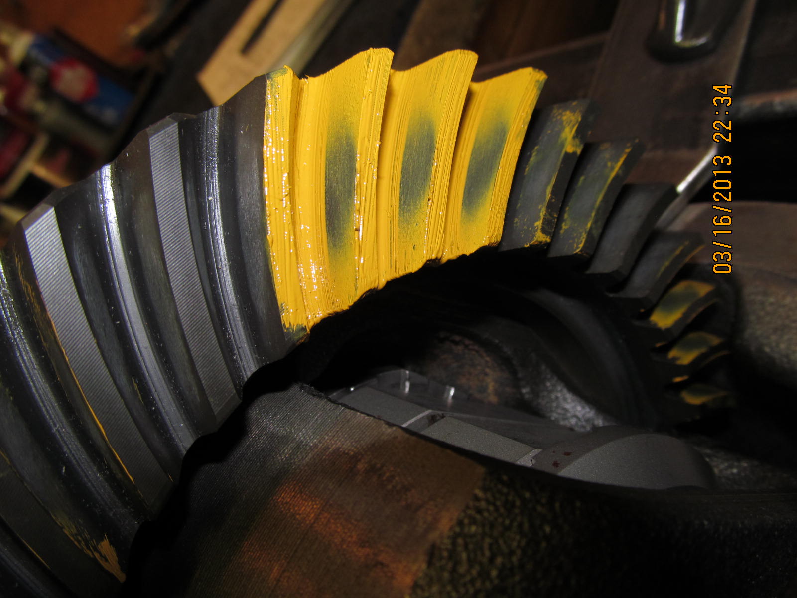
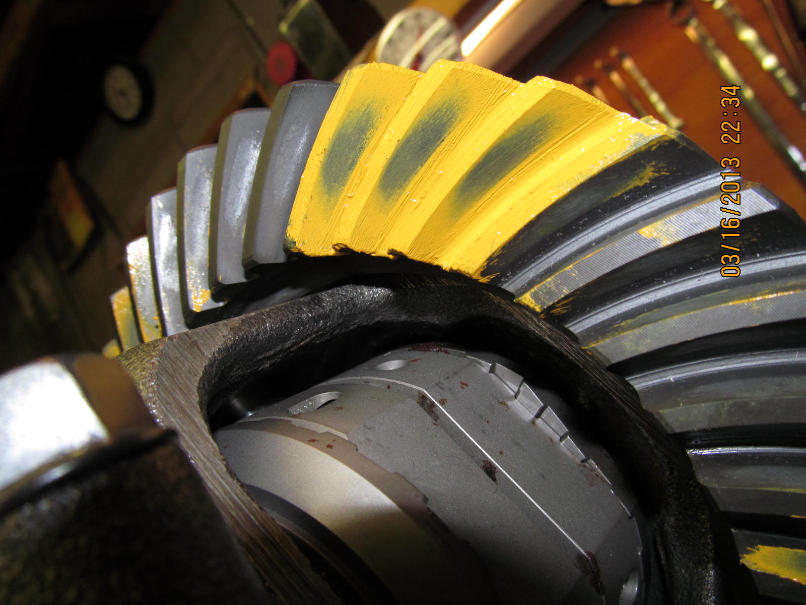
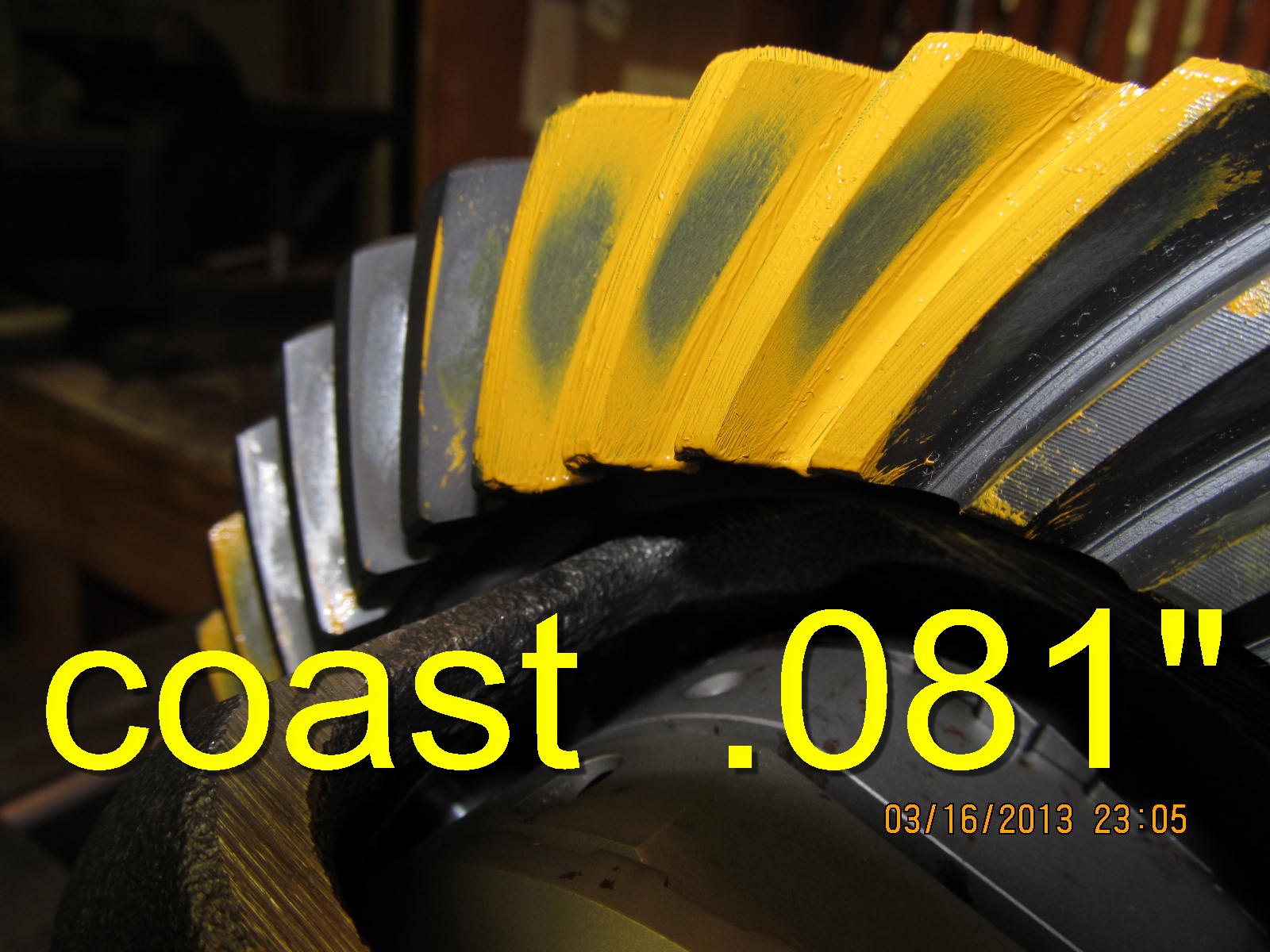
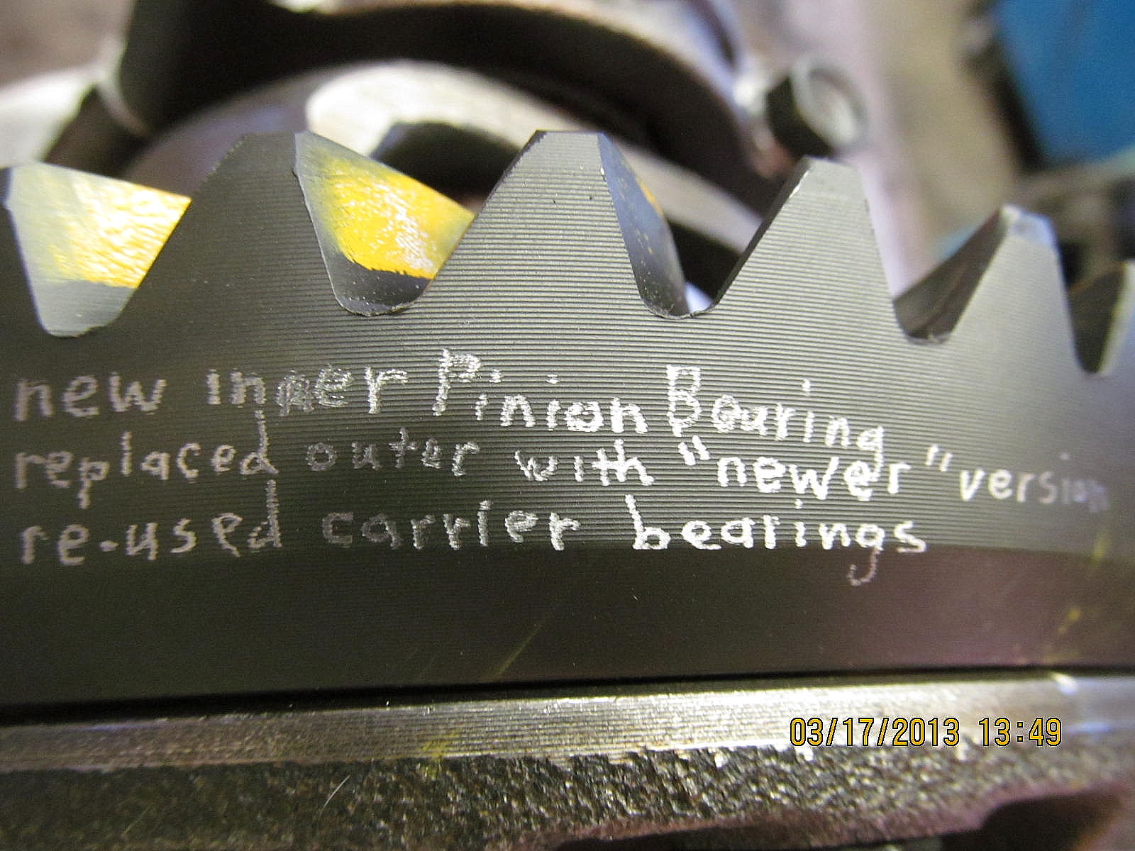
gear markings to help identify them.
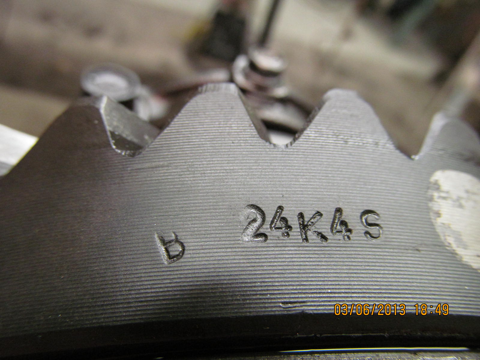
This is the Genuine trade mark. Crappily stamped uneven
characters.

Parts are now on order from JT's. In the meantime, this 3rd can be
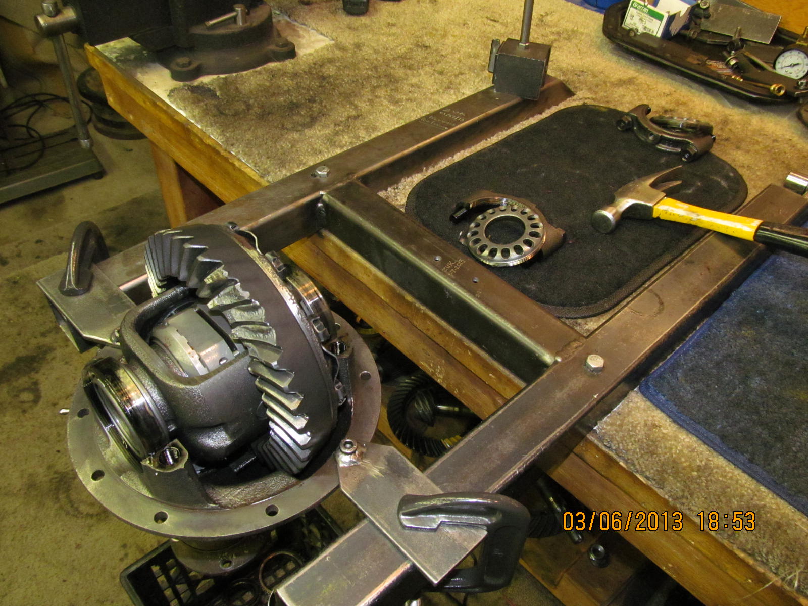
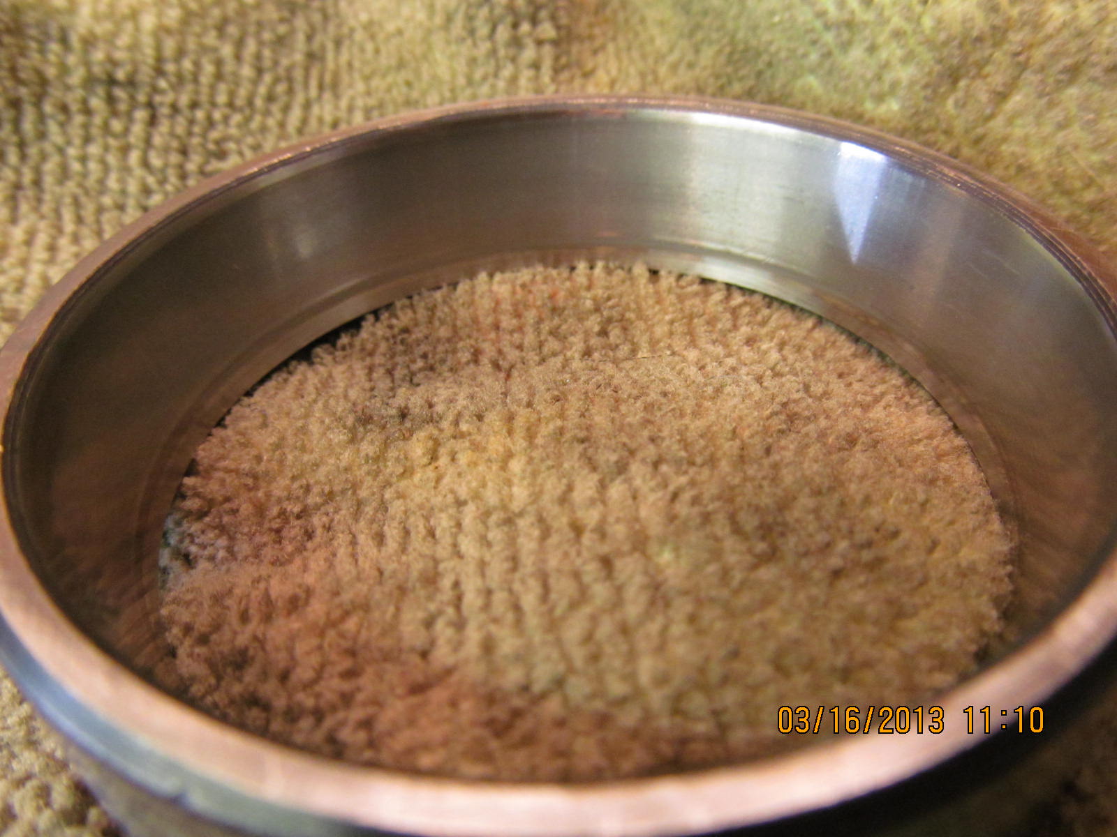
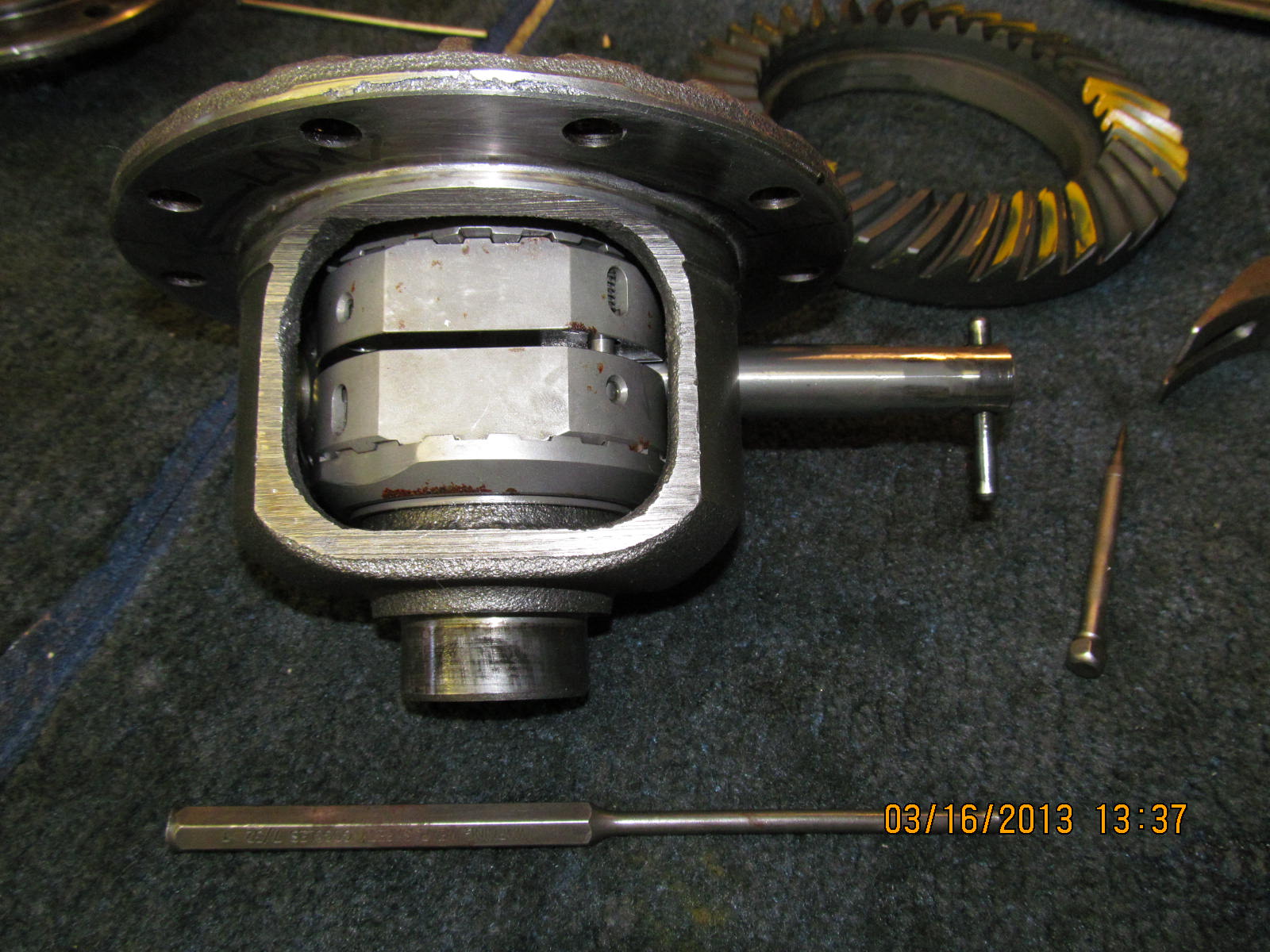
torn down and cleaned up.

John requested saving what bearings we could. Carrier bearings
are ok...just will lighten up on the pre-load final values.

CB races look ok also.

Pinion nut is wizzed off with the electric impact and the pinion drops
down on its own accord.

This one had a crush sleeve...a solid collar will be replacing it.

The light does strange things to some of these digital camera
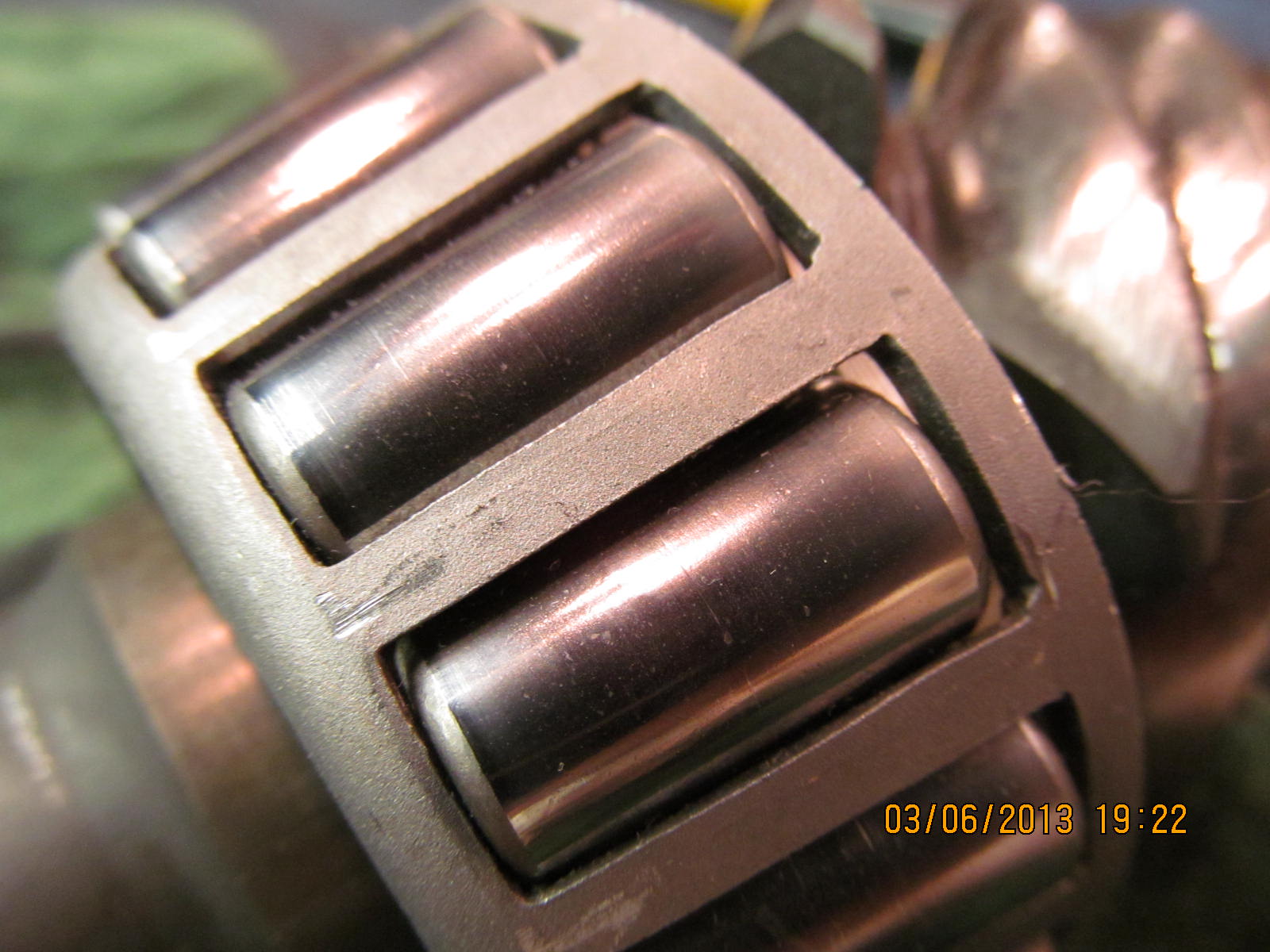
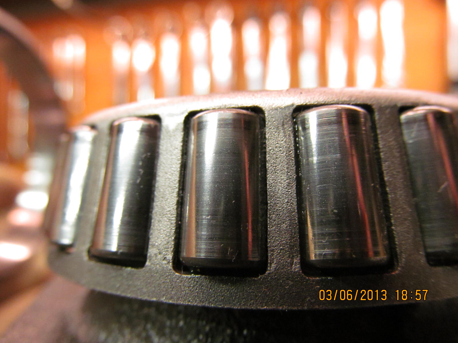
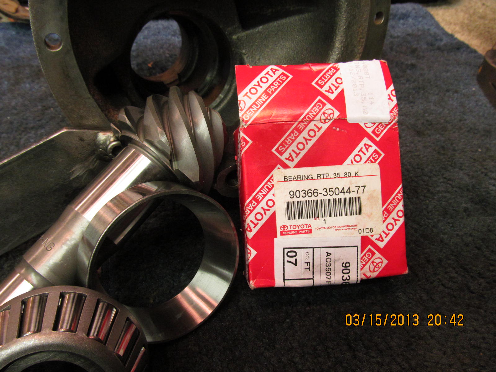
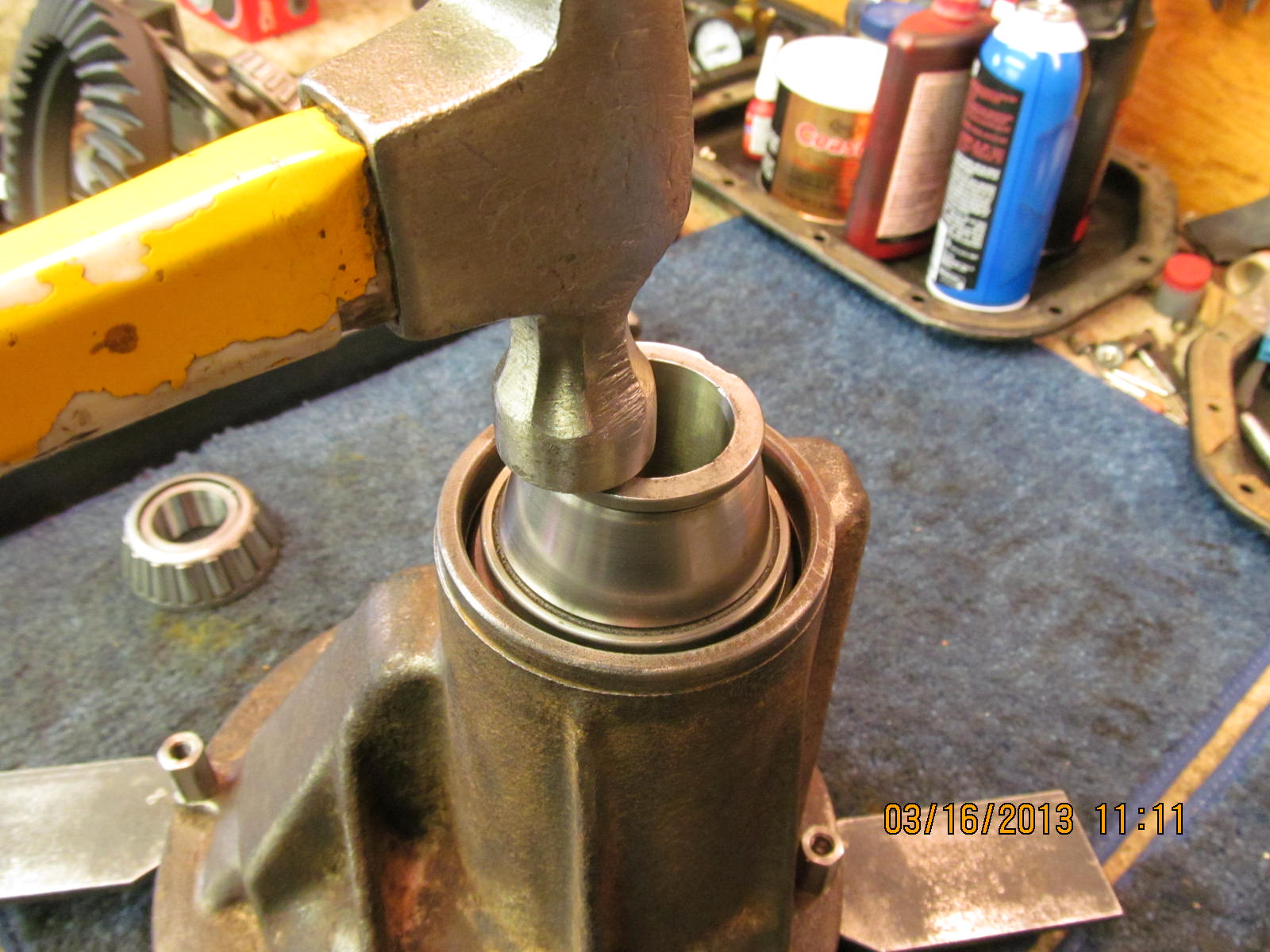
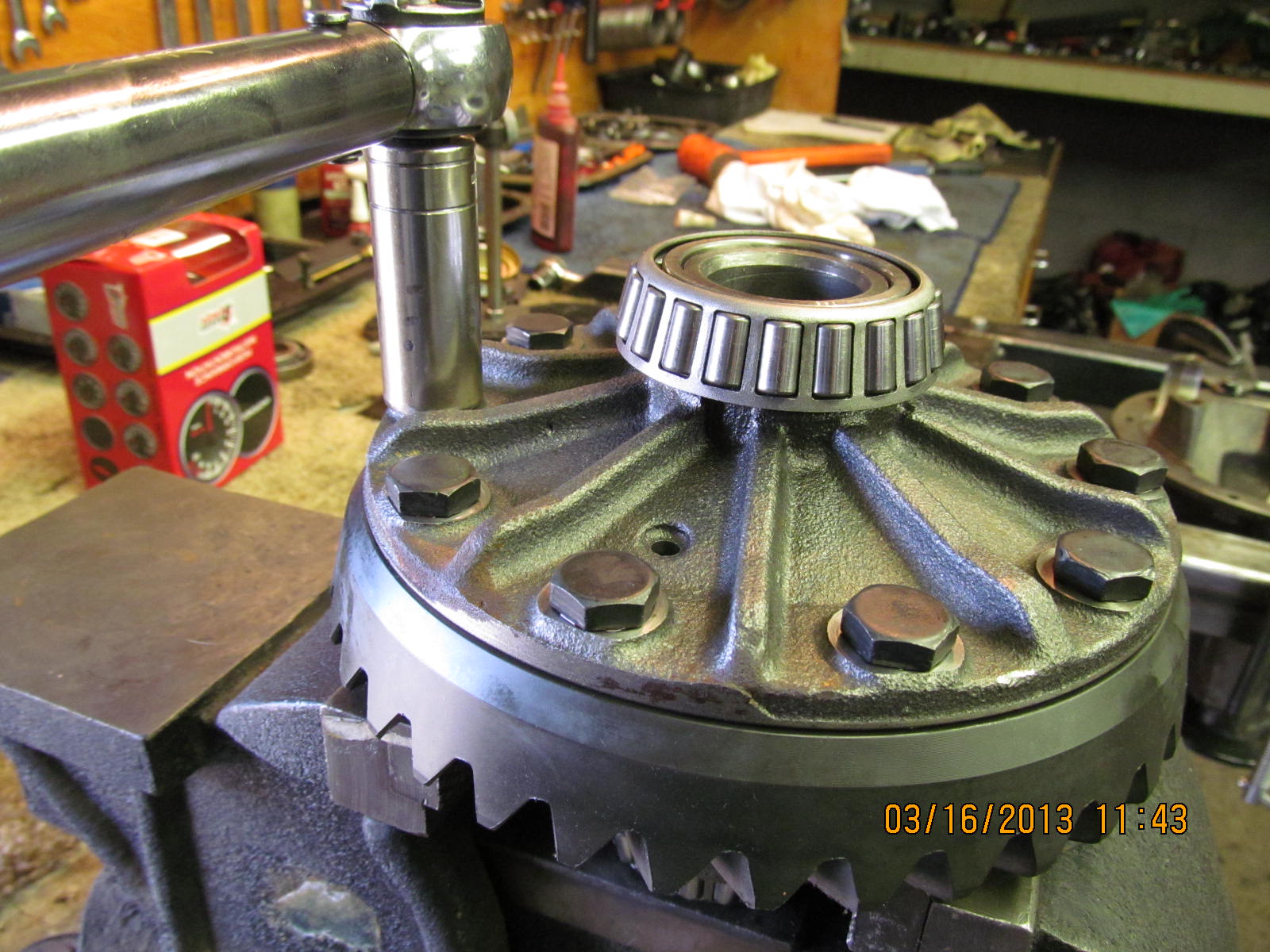
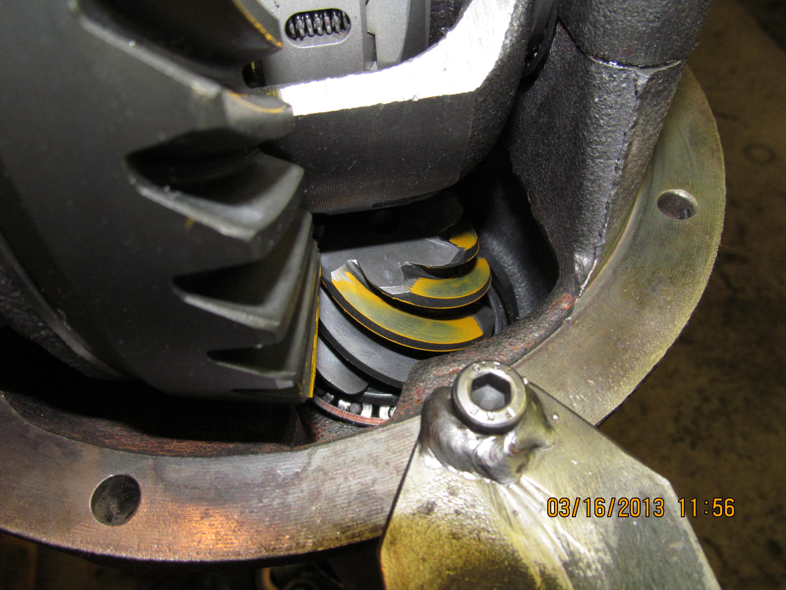
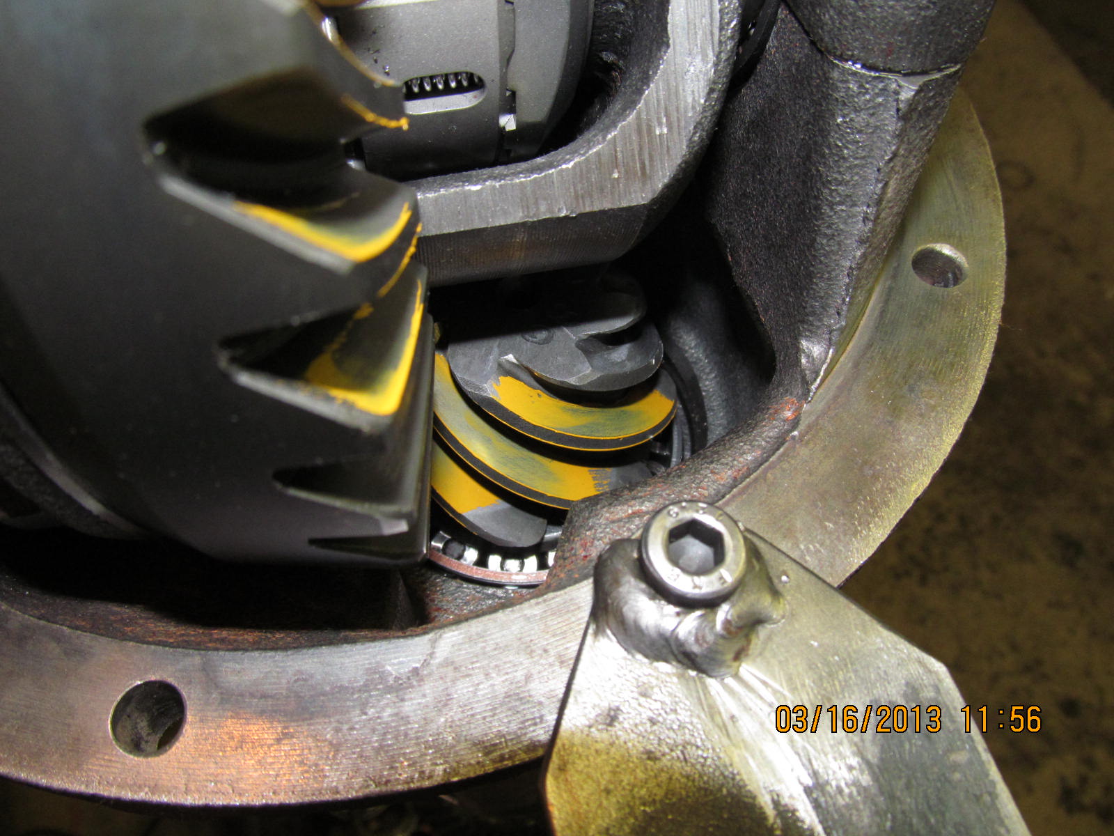
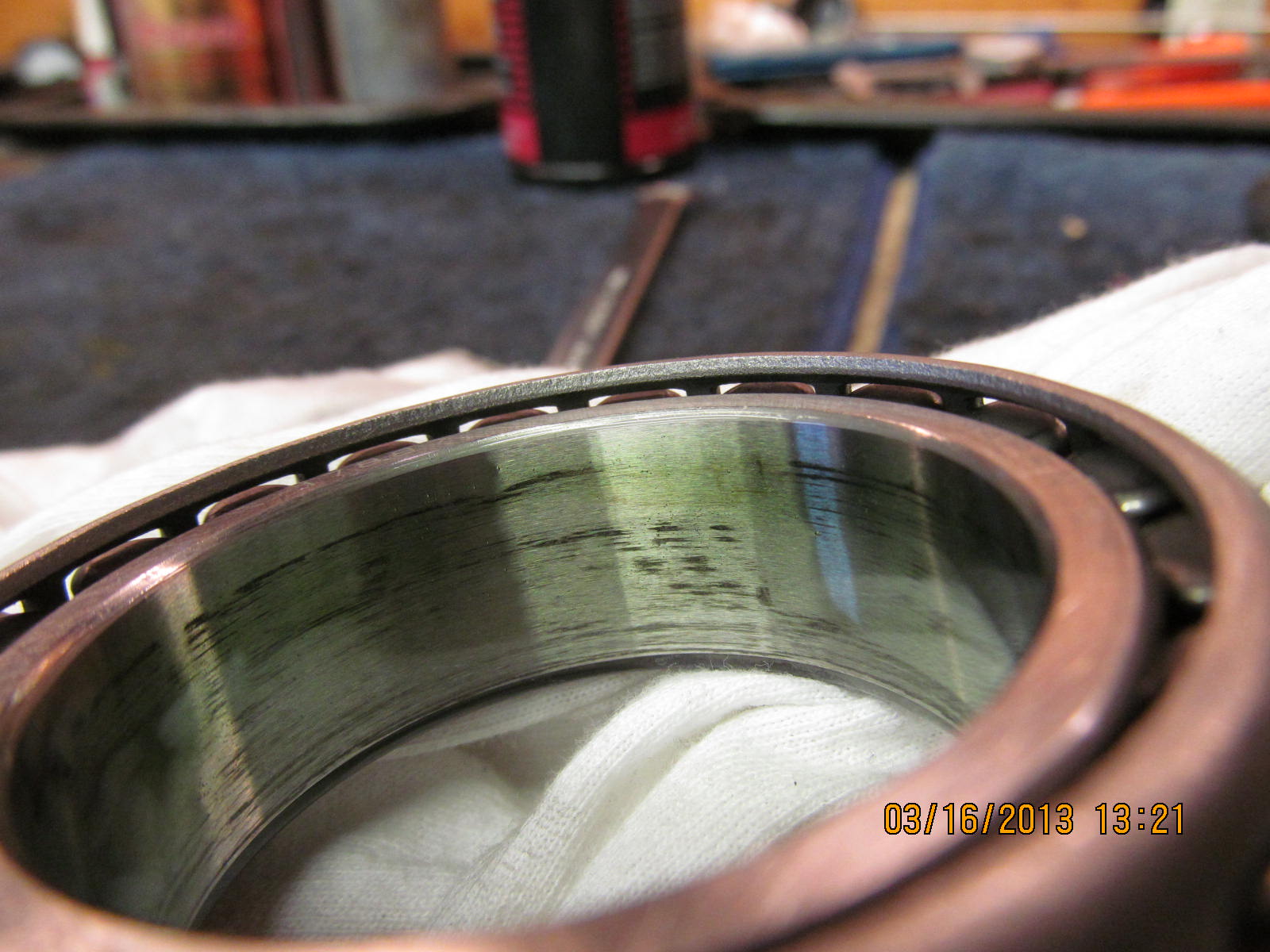
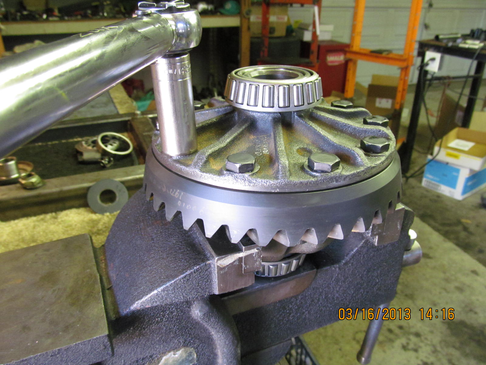
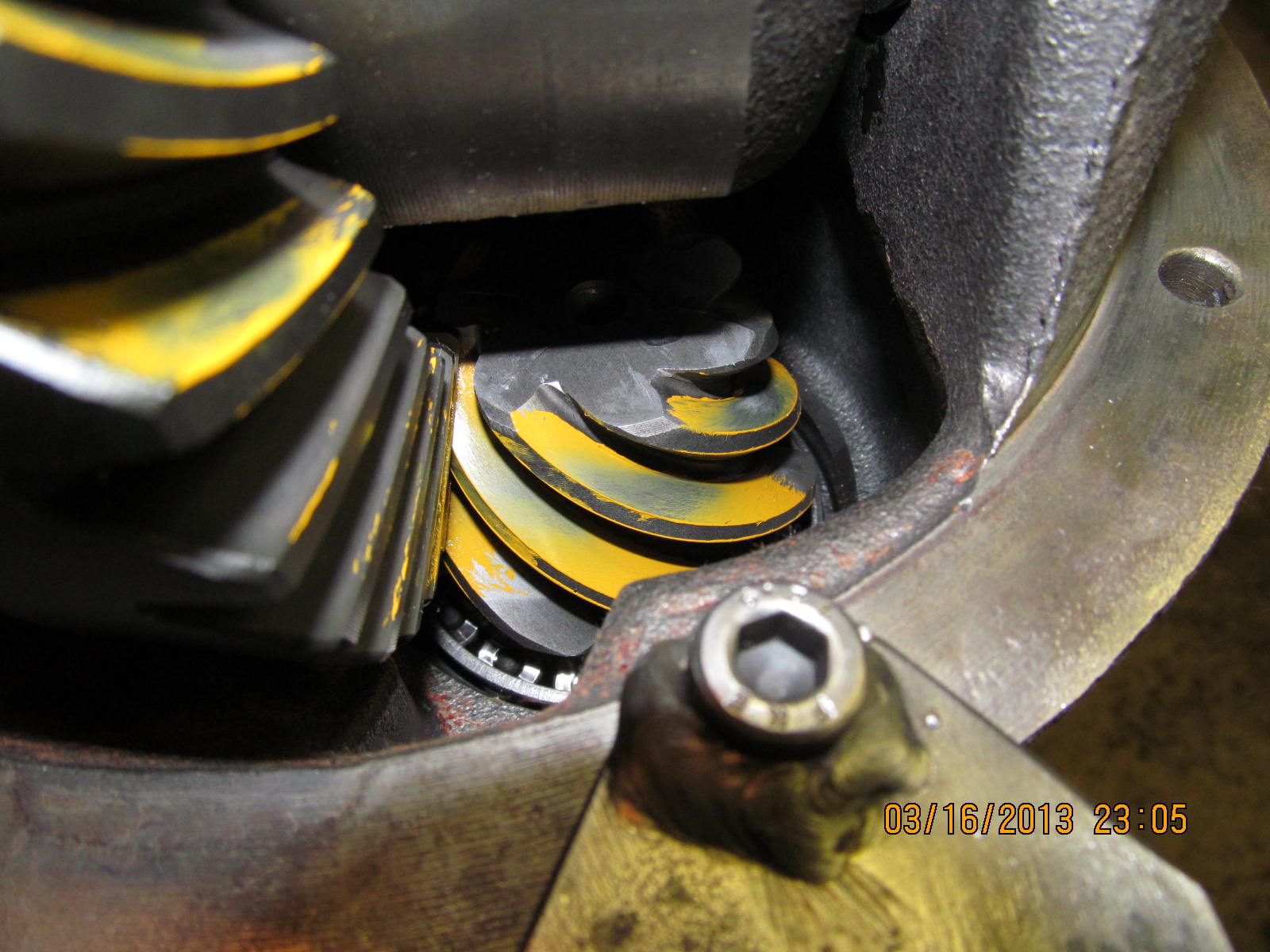
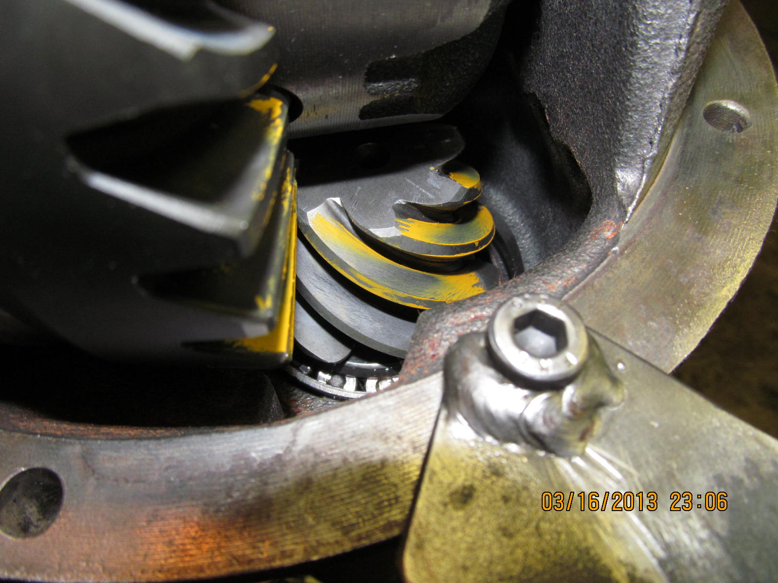
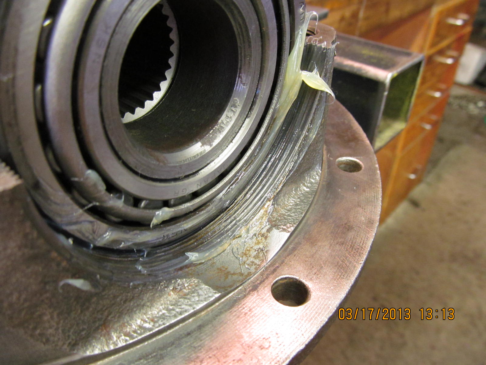
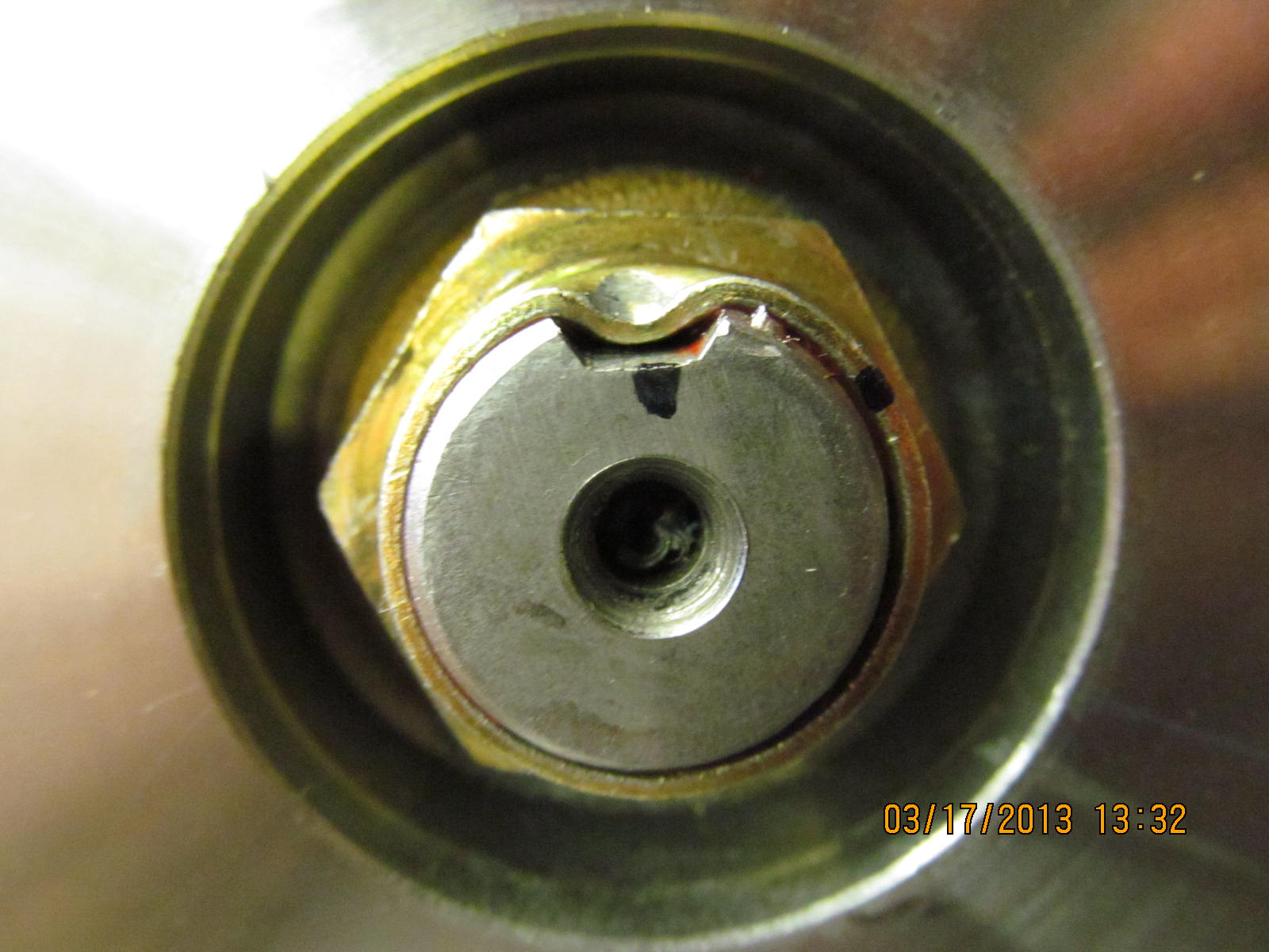
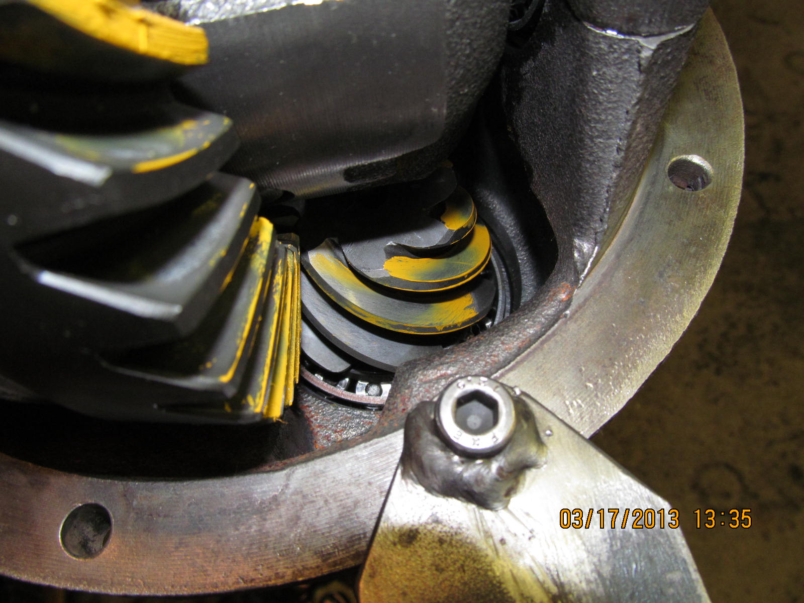
pictures...this 32307 bearing is in ok shape and because we
will be installing a V6 style pinion in this "4 cylinder 3rd"
means a brand new skinny bearing will be used. A skinny bearing
is what I am calling the "low profile " inner pinion bearing
that the 1986 thru 1985 trucks use in the 4 cyl 3rds....even
though those 4 cyl 3rds actually use the long pinion head V6 pinions.

....

Small outer pinion race...some pitting. I have a slightly used
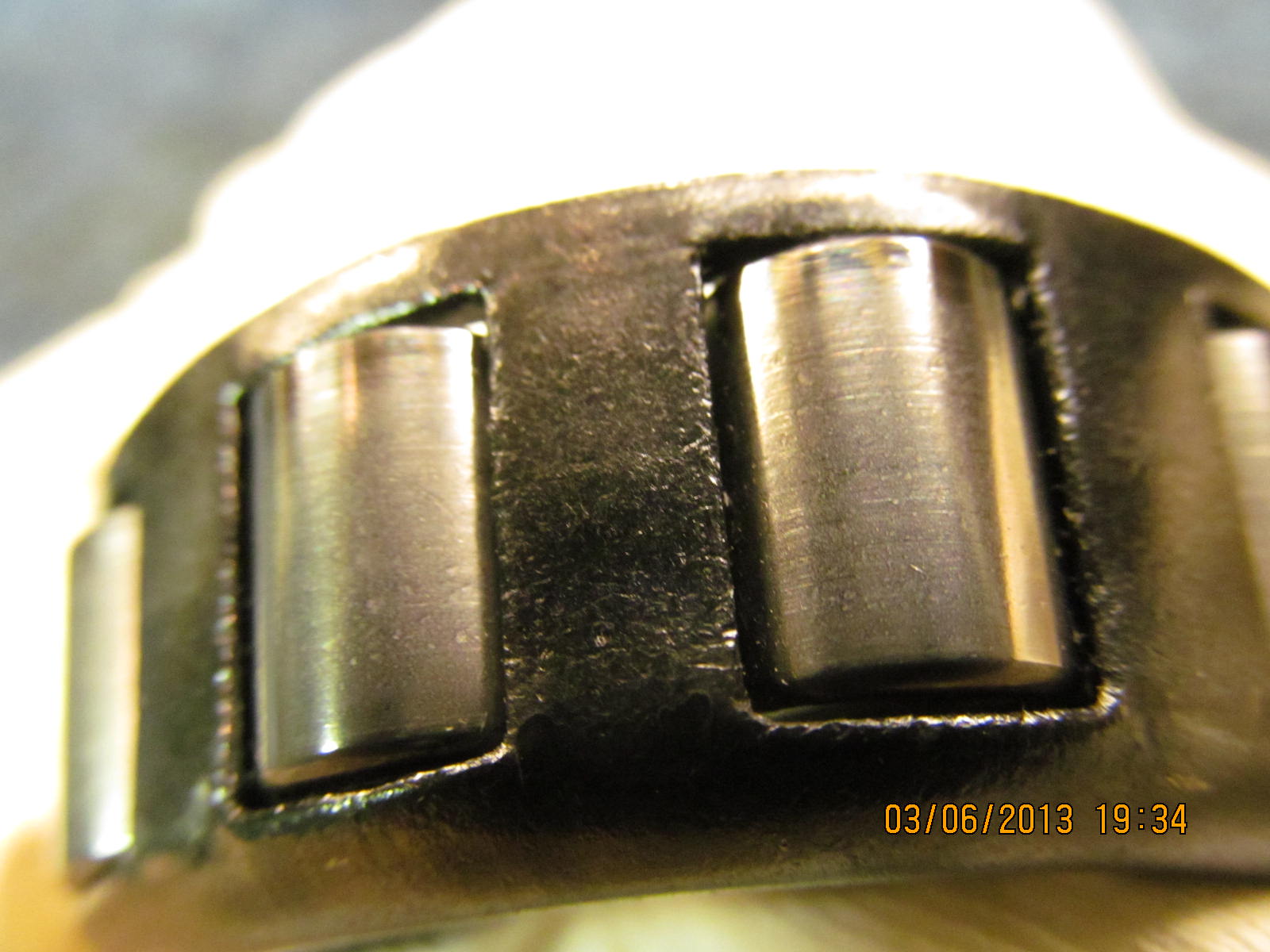
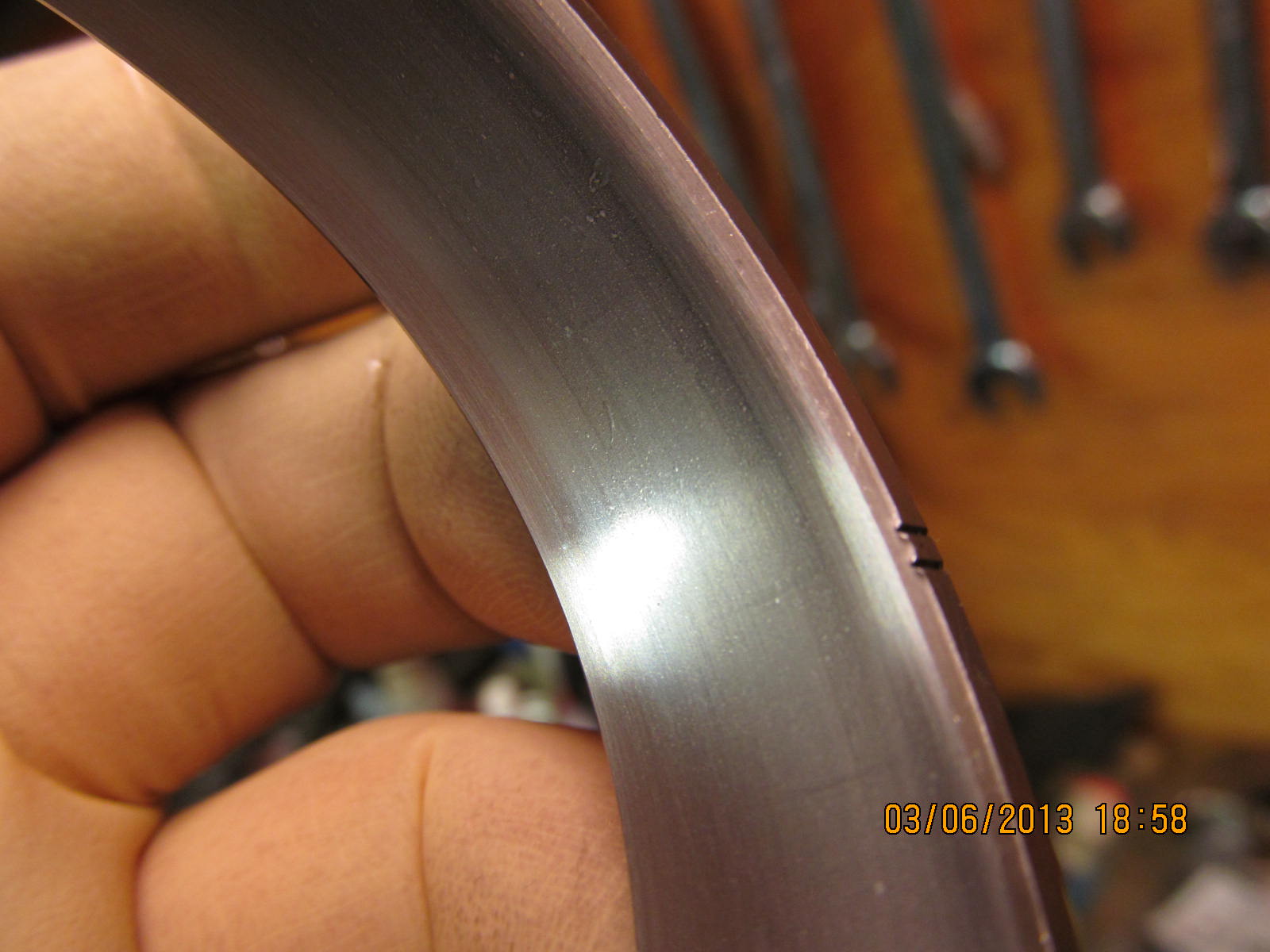
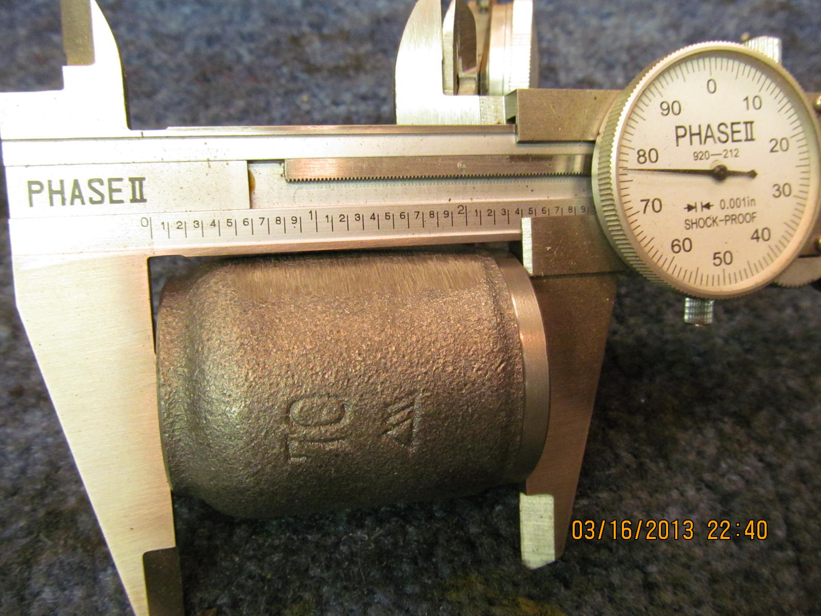
alternate bearing that is in much better shape than this one.

Larger inner pinion race...ok shape but will not be used.

27 spline flange...

I cleaned it up with the high speed wire wheel....

....and the seal surface saw 1000 grade sandpaper. This surface is in
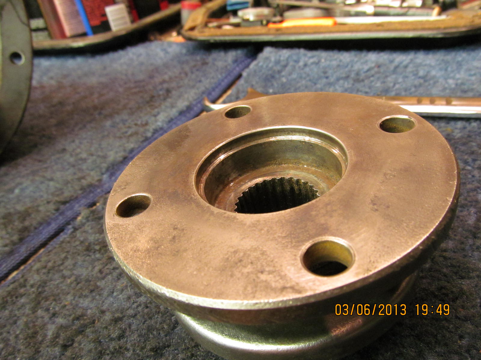
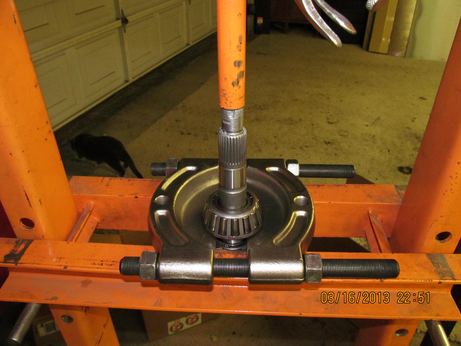
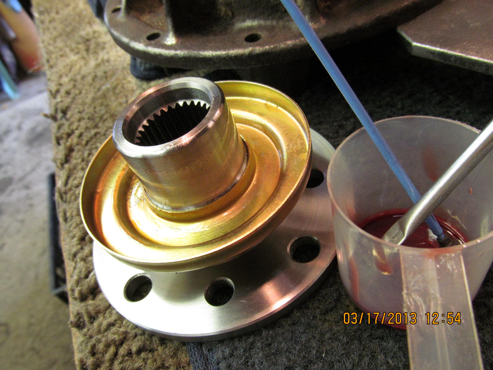
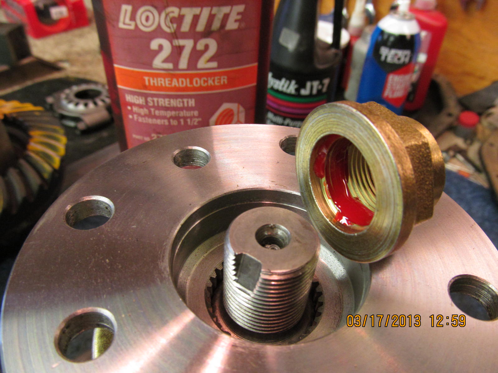
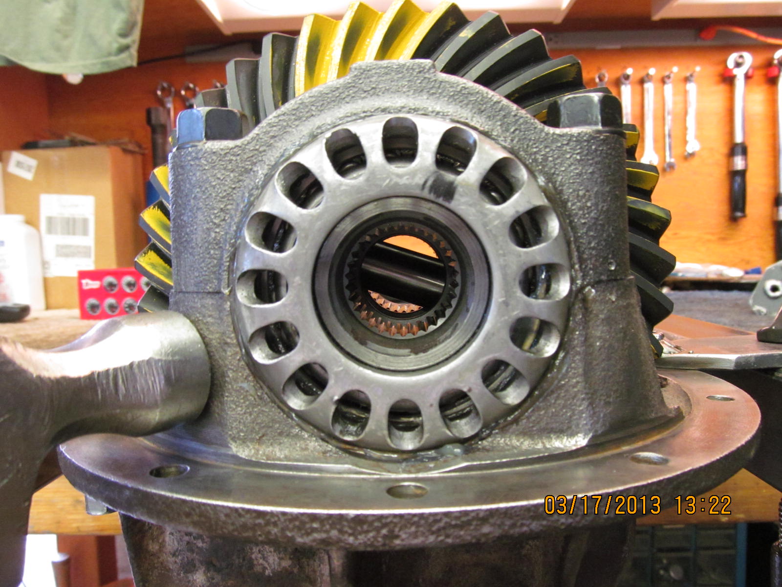
very good shape. The new 529 pinion is a 29 spliner so this 27
spliner will not be used.

The Genuine piece of ring gear is removed and tossed away.

3 days later, a package arrives from JustDifferentials. :)

Carl sent me the 29 spline heavy duty Nitro Gear 529 with
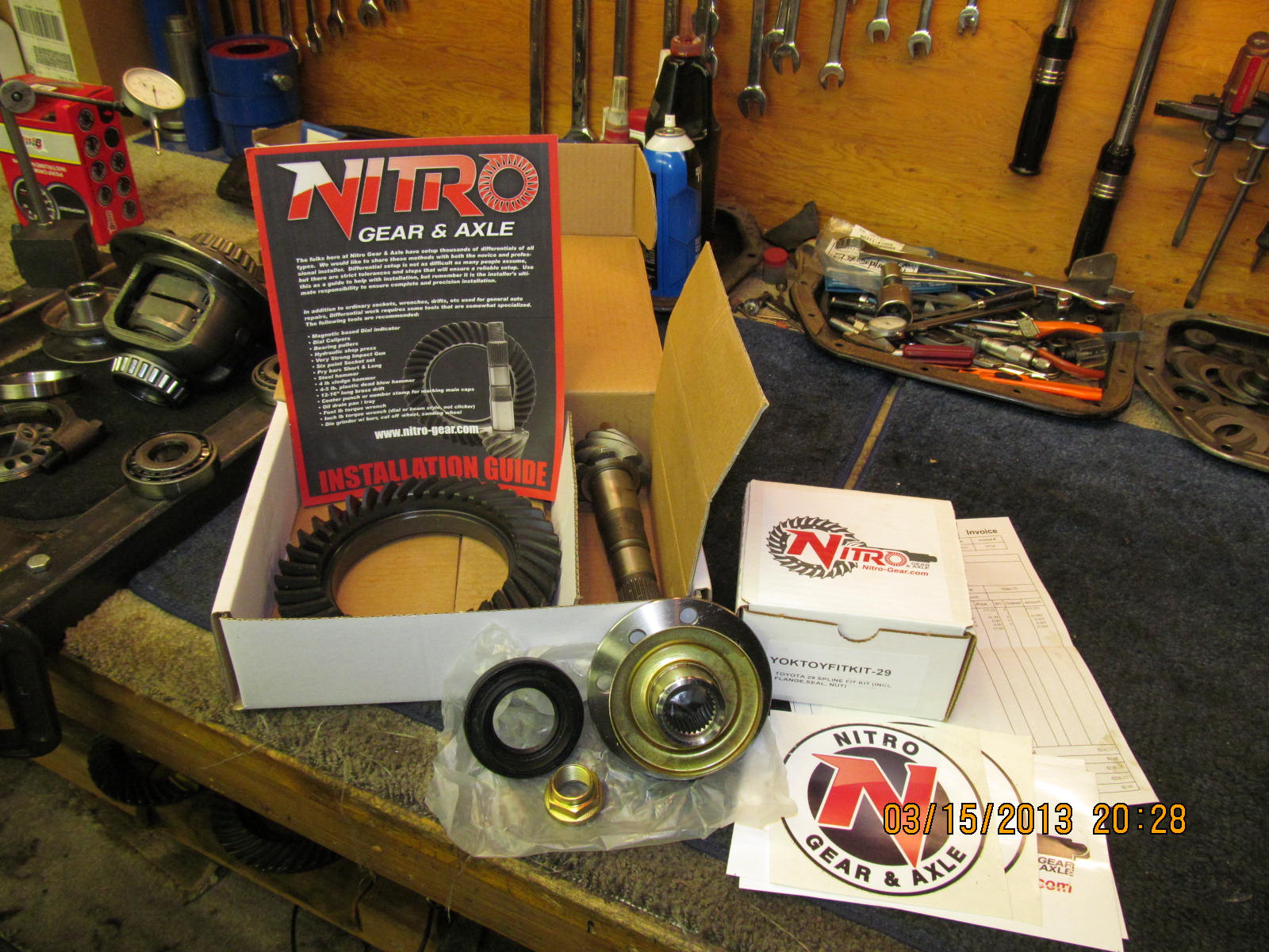
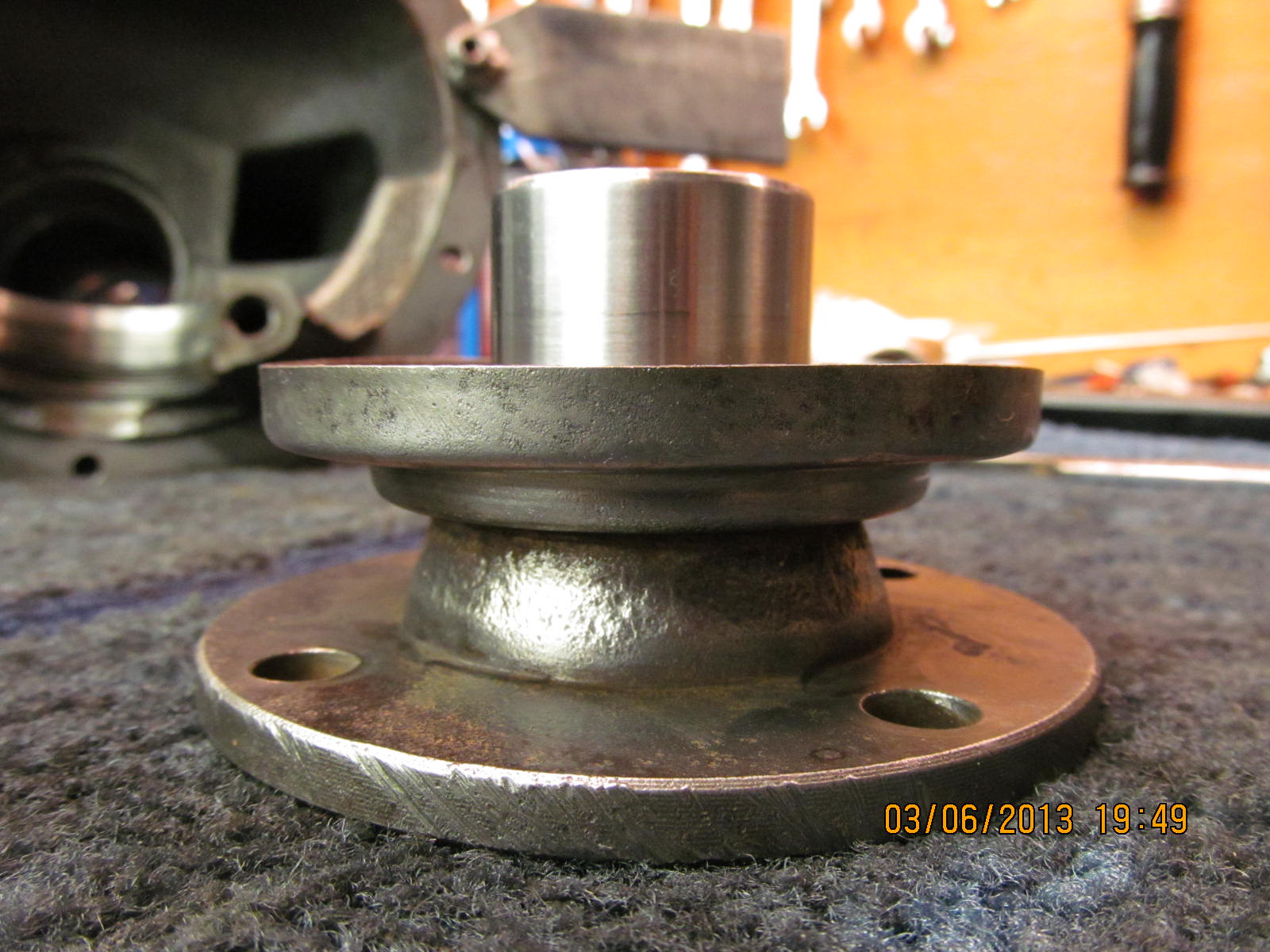
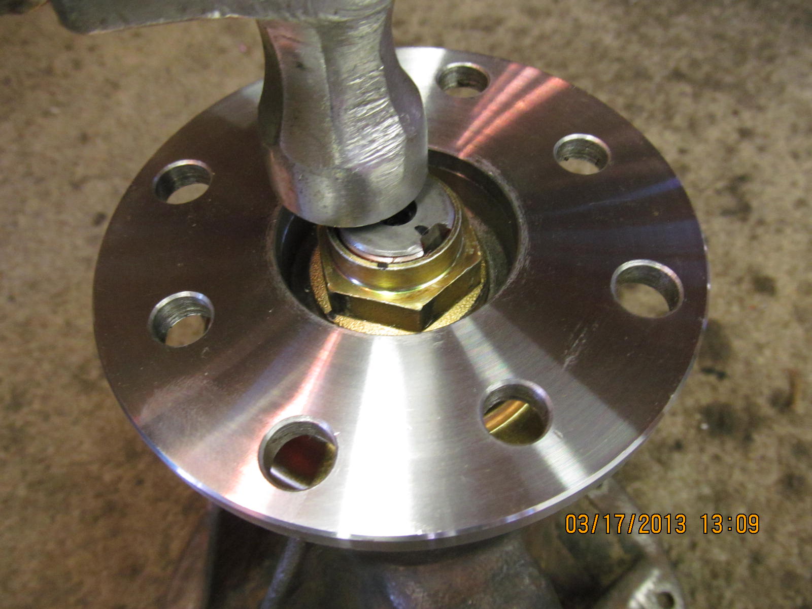
matching 29 spline flange and seal and nut.

Markings on the Nitro Gear.

This is a 4 cylinder 3rd....with a V6 pinion....that requires this
"low profile" OEM bearing to make it work out perfectly.

Inner race is pressed in.

The replacement outer pinion bearing and race that I located ....still
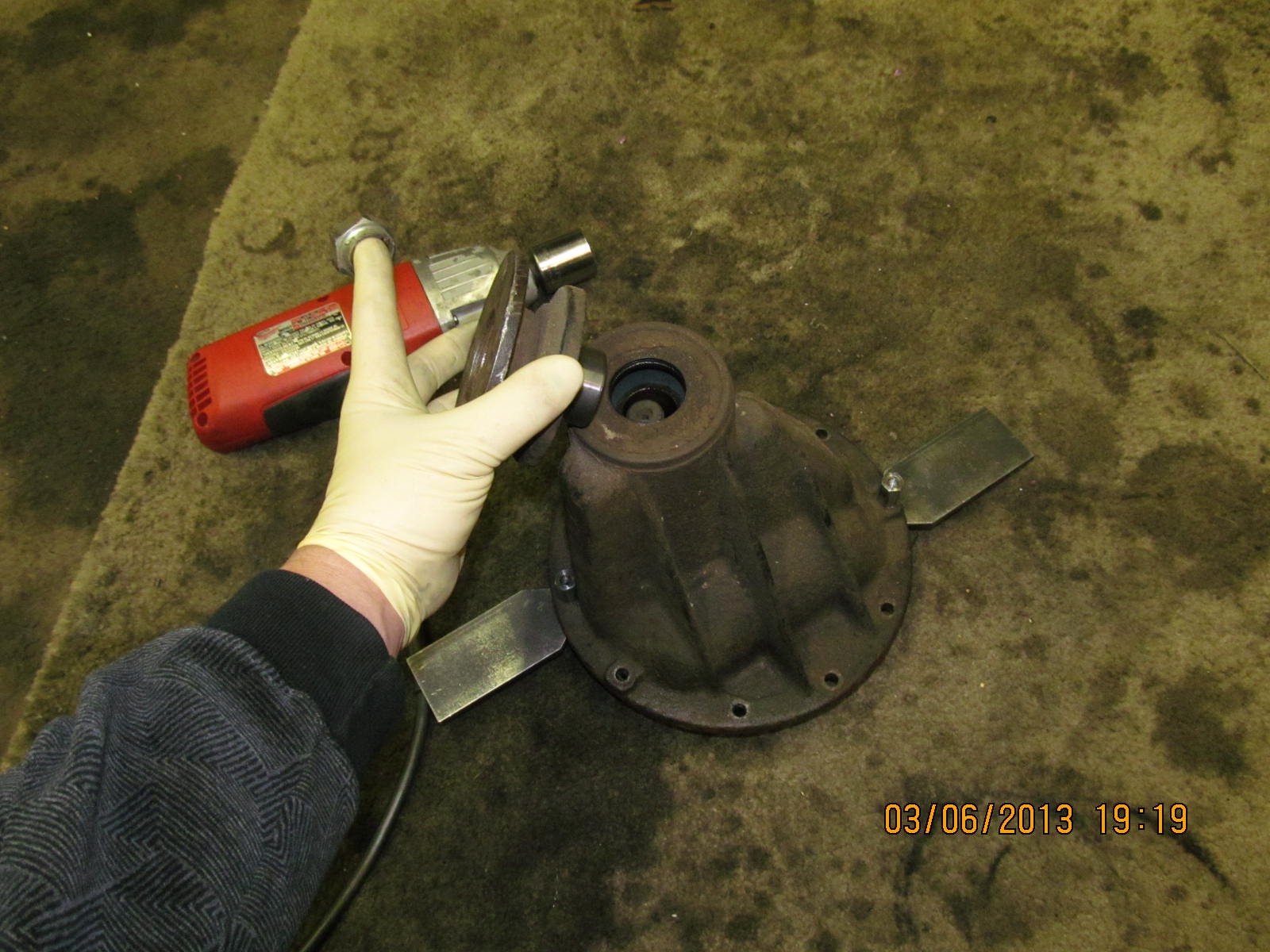
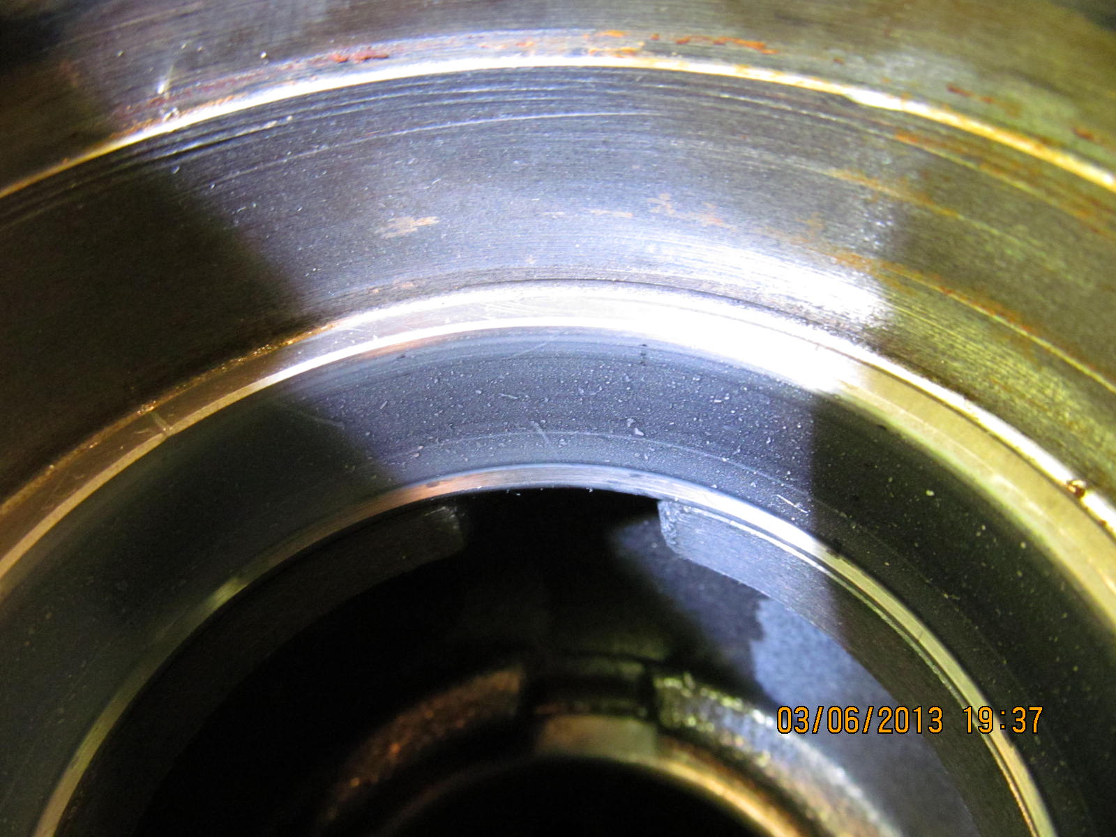
a used one but twice as good a shape as the original pitted one. Since
this outer bearing/race is a used one, I will factor that in when I
set the PPL.

Tapping the outer race in place....

...and pressing the .0785" pinion depth shim on the brand new
inner bearing.

Mounting up the pinion assembly inside the bare carrier housing
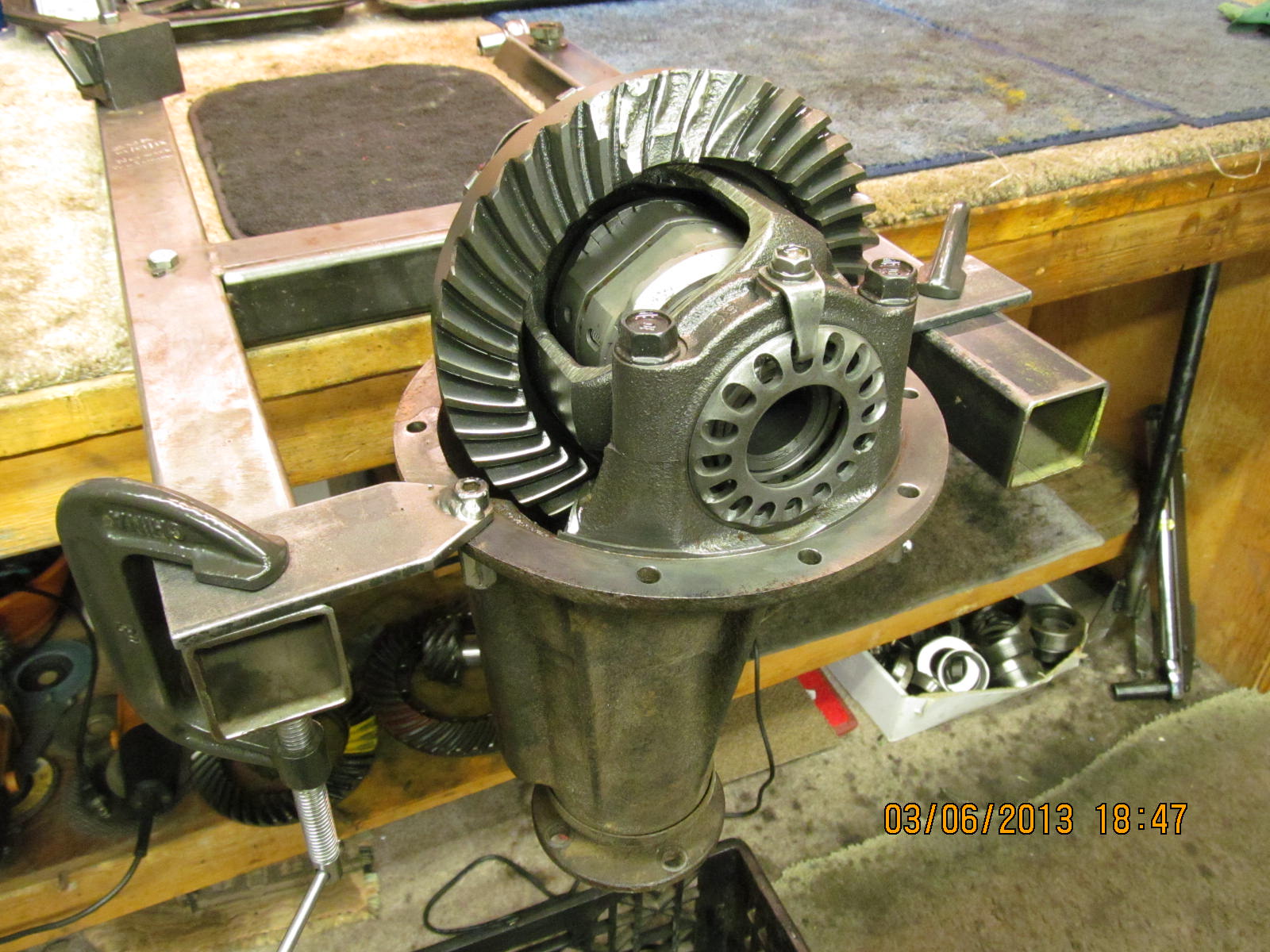
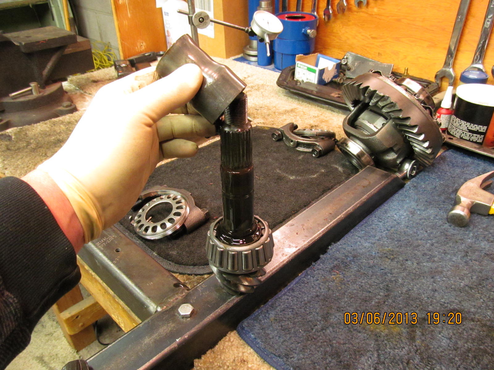
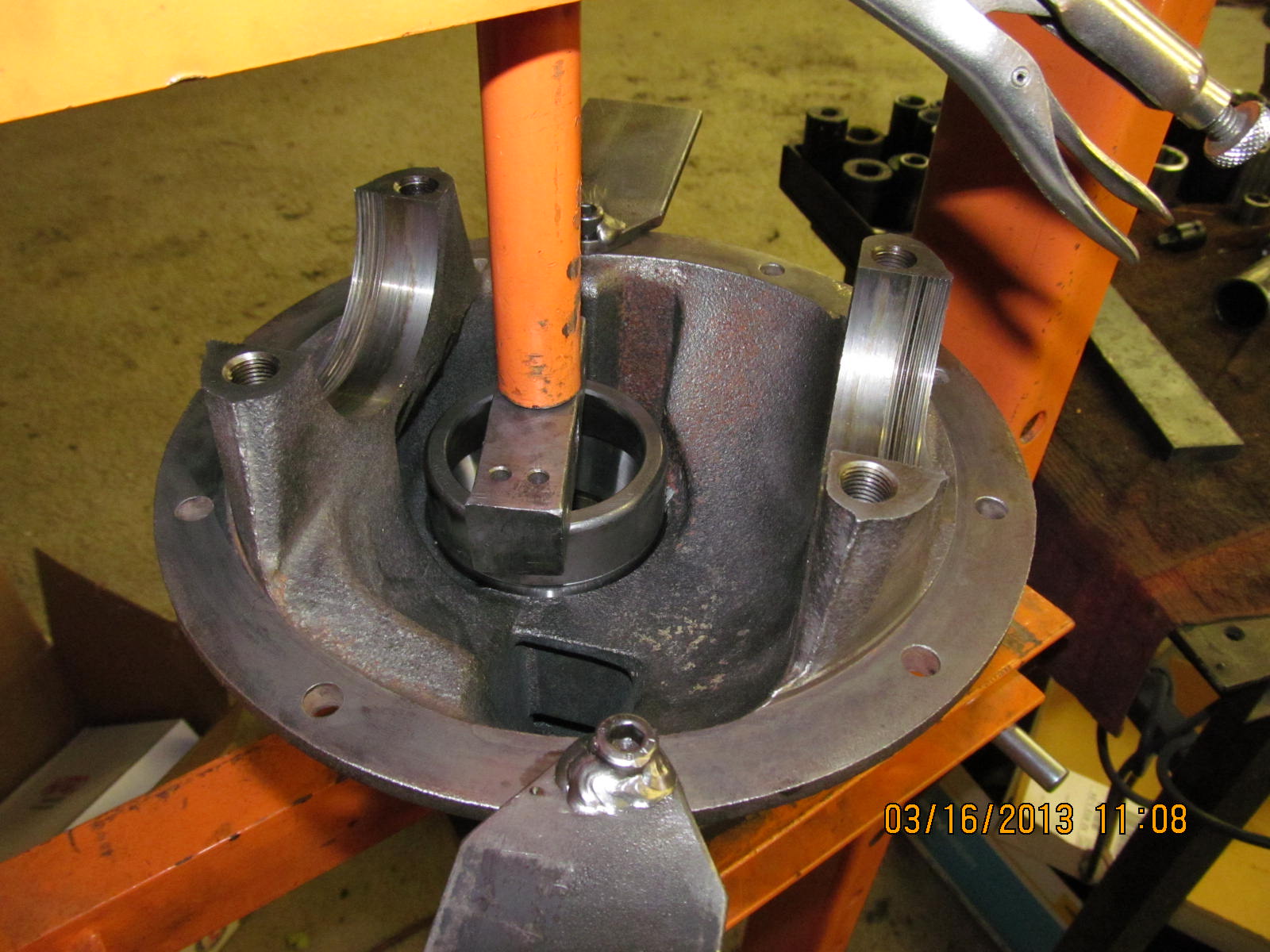
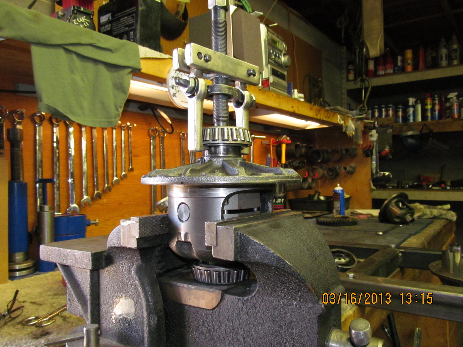
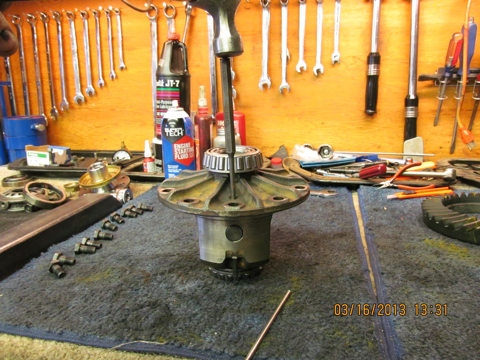
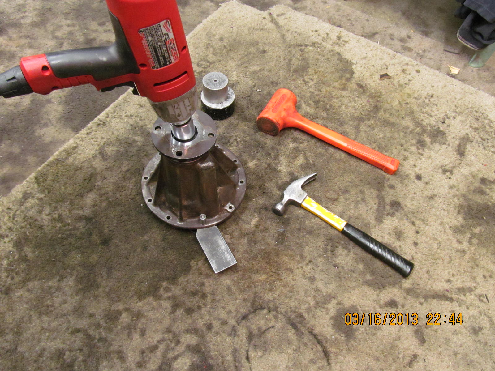
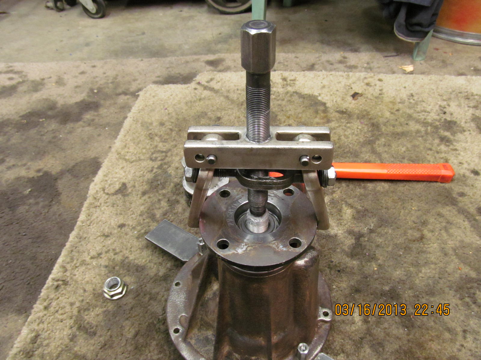
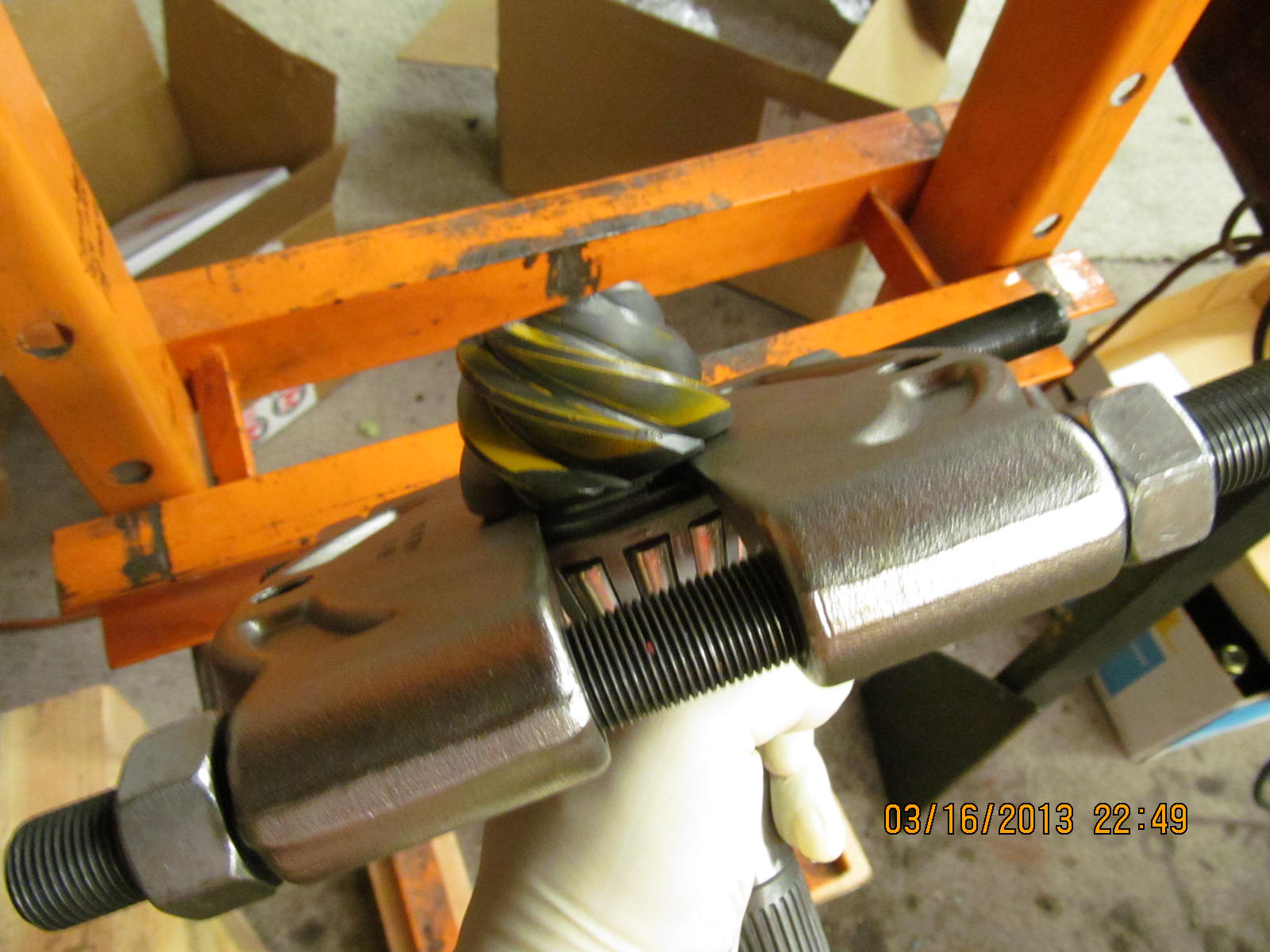
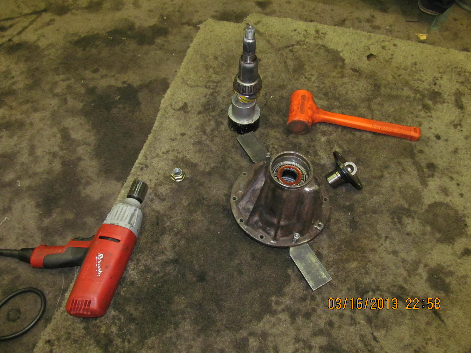
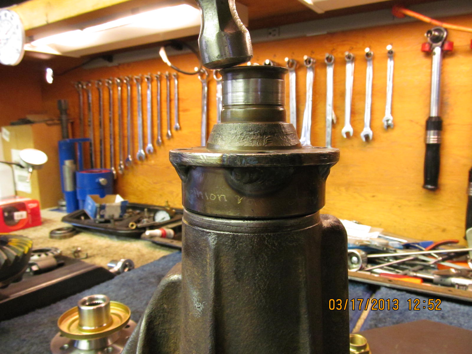
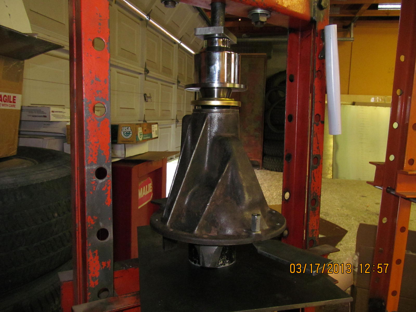
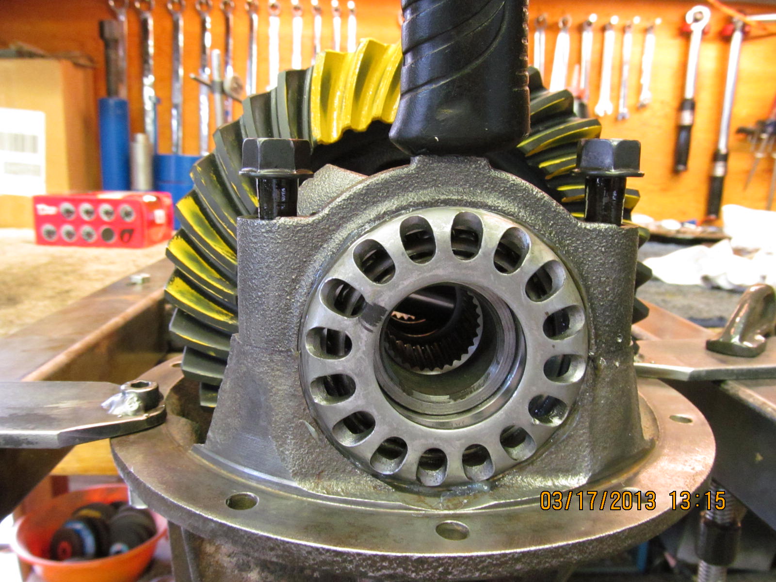
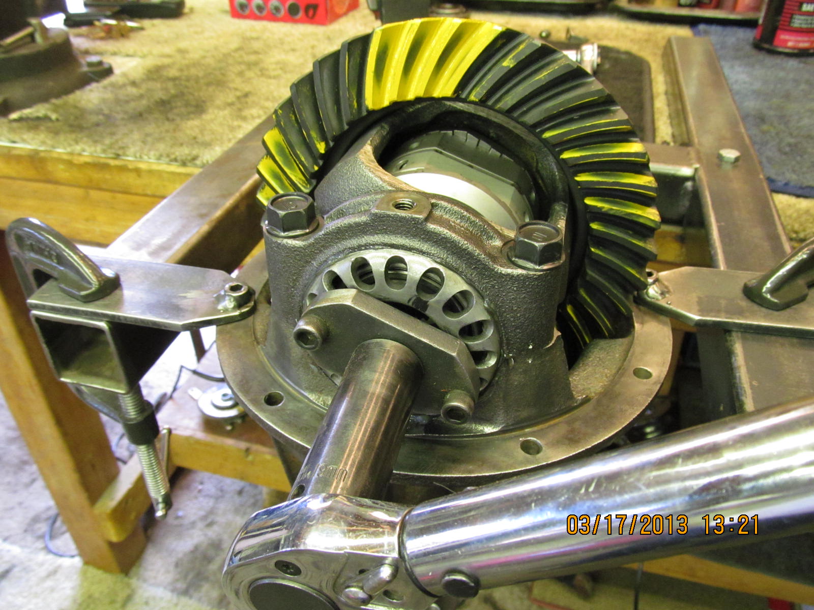
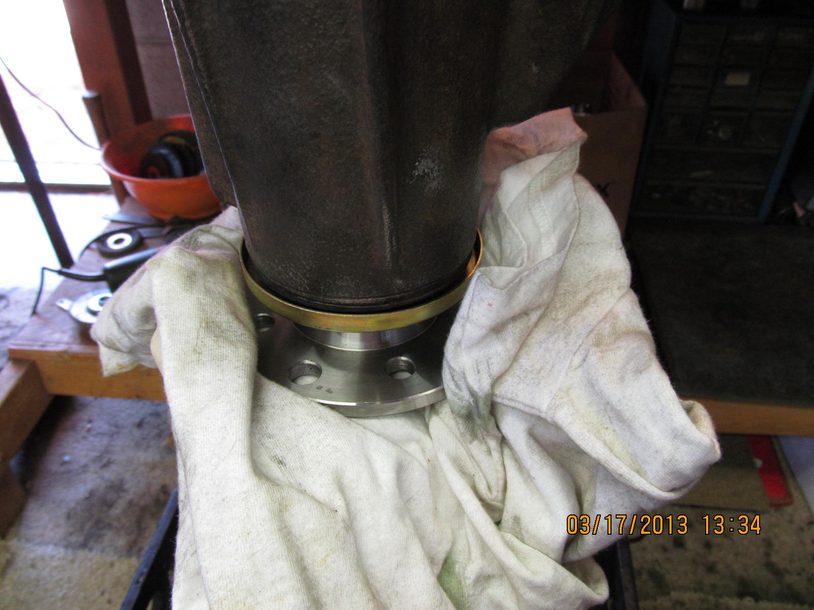
is fairly easy. Place housing over pinion...outer pinion
bearing....29 spline shop flange...tap down with lead filled
plastic hammer....start the 30mm nut and wizz it down with
the electric impact. Oil the bearings and continue the gradual
tightening of the nut until some pre-load is felt.

This is ok for a paint depth check...not very critical at all
at this stage.

The open differential case is checked with a very robust course file
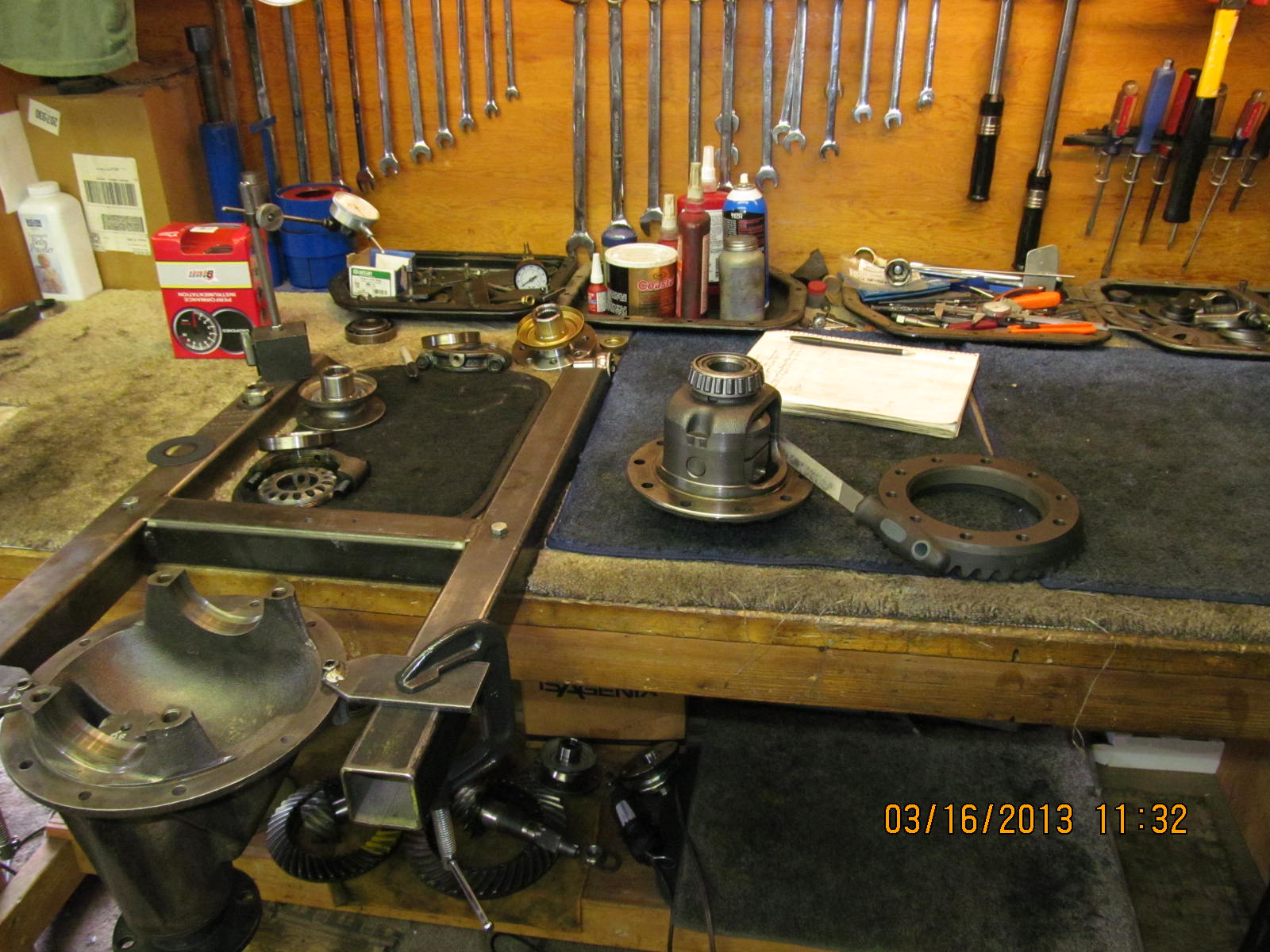
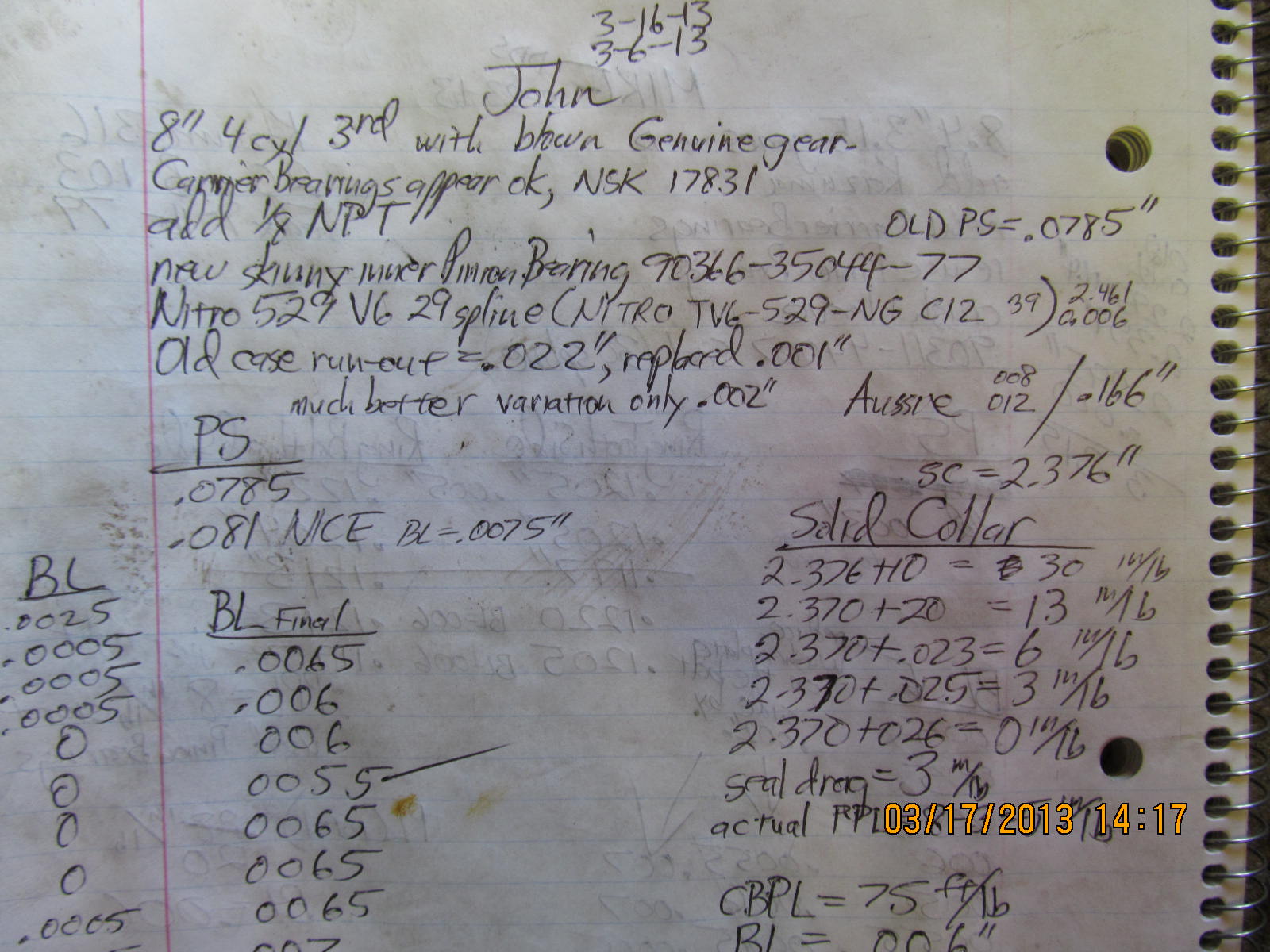
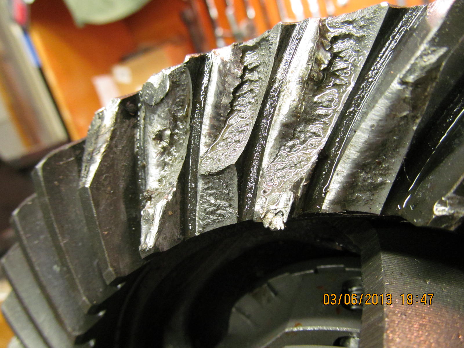
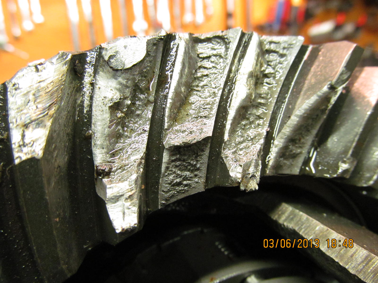
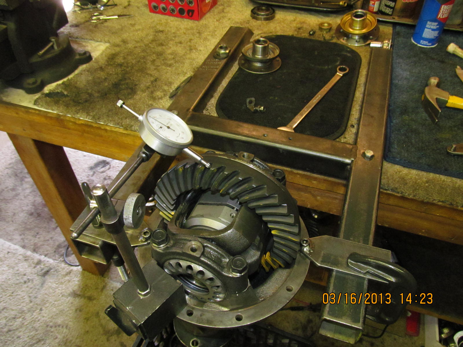
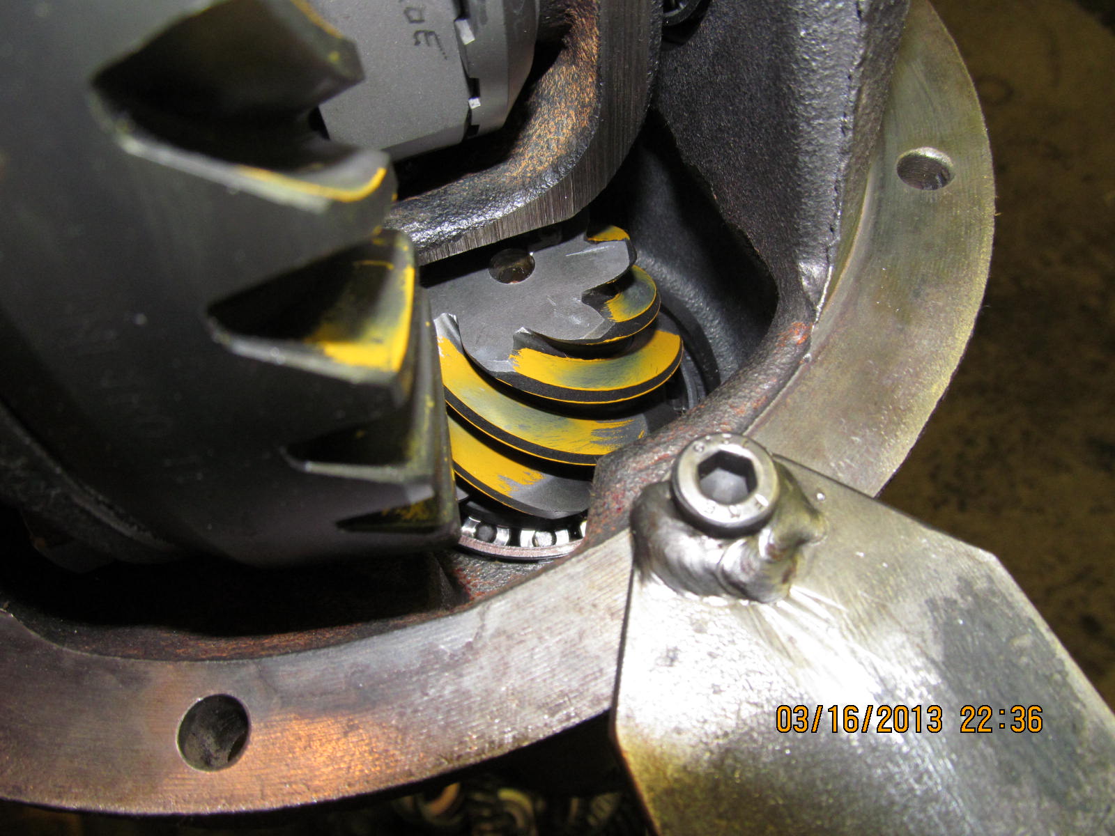
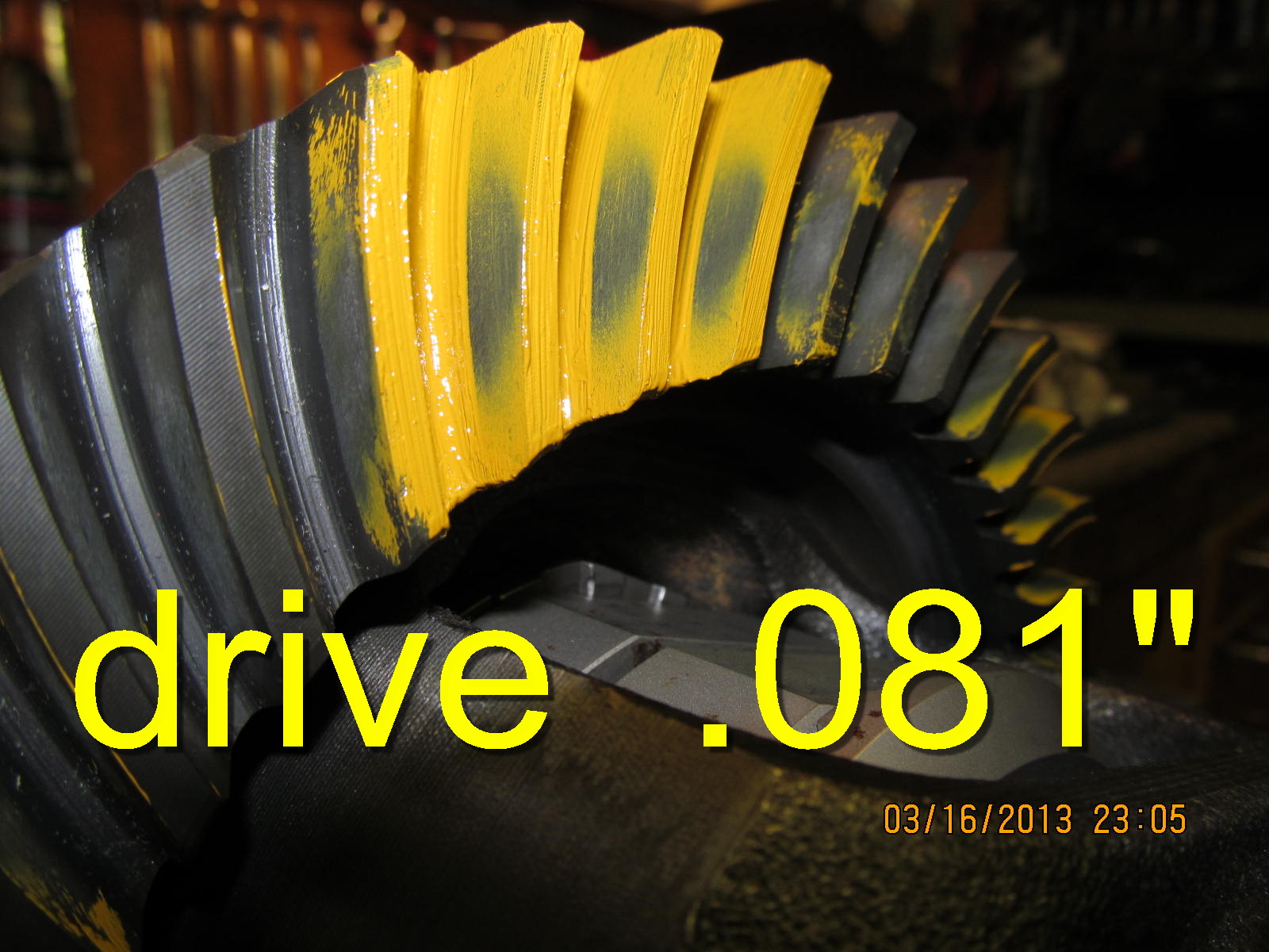
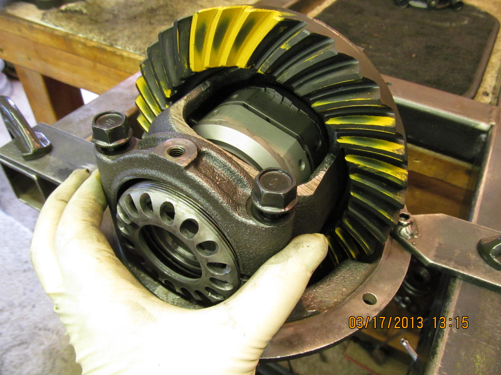
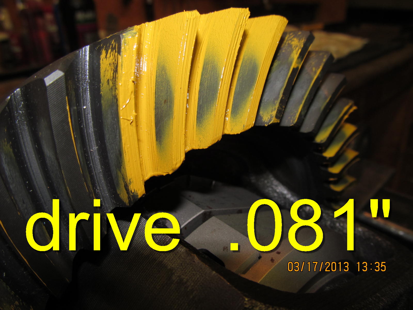
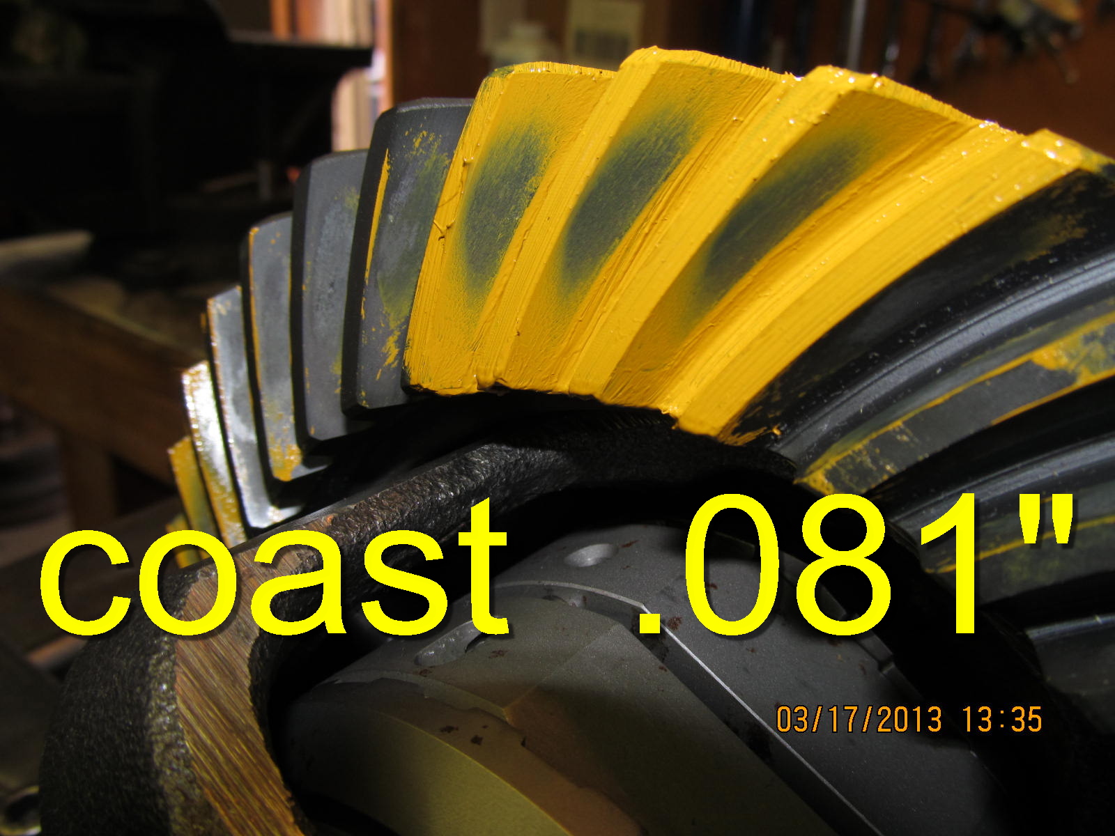
and nothing unusual was found. Ring gear also saw the file.

Red loctite is applied to all 10 fine threaded 11mm x 1mm bolts.

The usual 75 ft/lbs.

hmmm....backlash varied from ZERO to .009"....not good.
I was tempted to think that these Nitro Gears were
manufactured wrong but these gears are known to be
excellent gears. Logically, the case that the ring is
bolted to must have excessive run-out.

But, I can still run a pattern check and this tells me that the depth
is "exact" and I can go a couple thou deeper to promote better
overall strength with no increase in noise.

Coast.

Drive side on the pinion tooth.

...............

Pull case...remove ring...place case back in carrier. I "zero'd" the
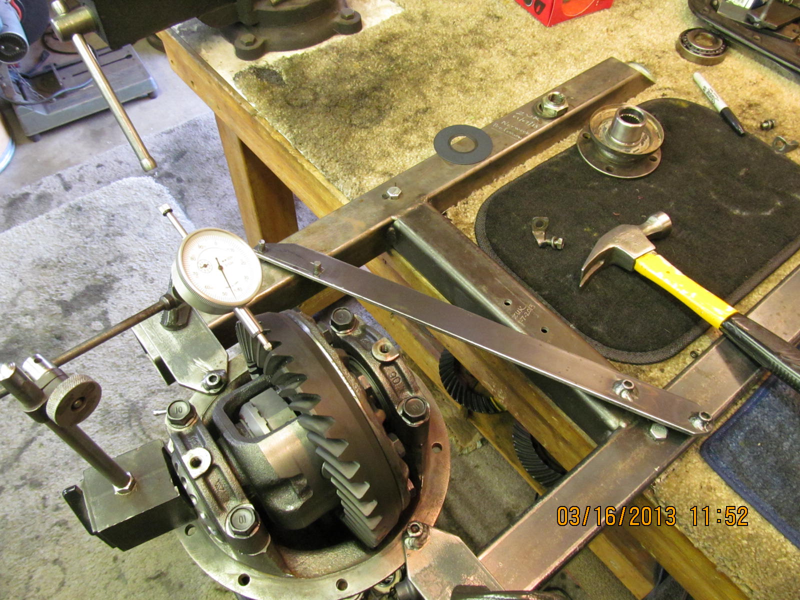
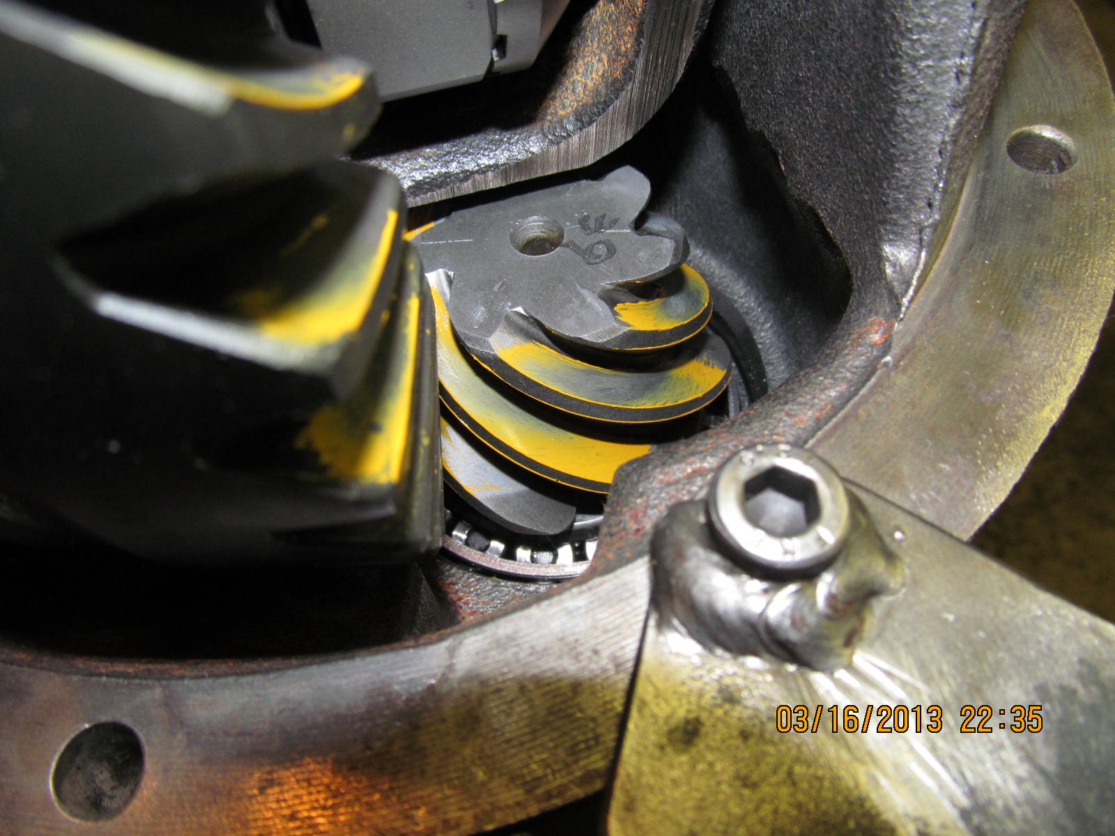
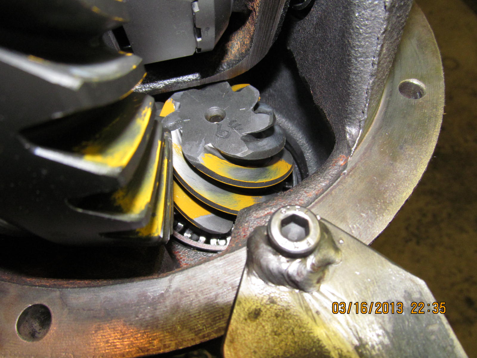
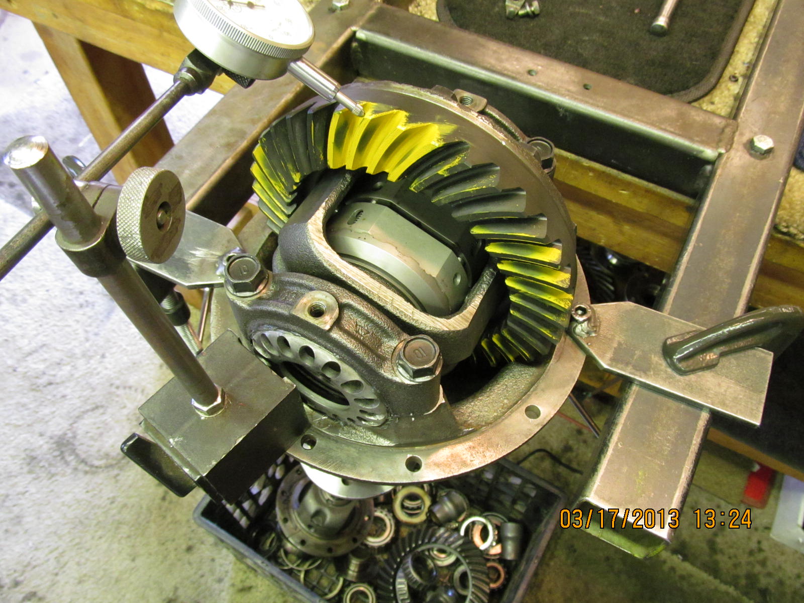
gauge on the low spot on the ring gear surface.

....and about 180 degrees on the other side, I found the high spot...
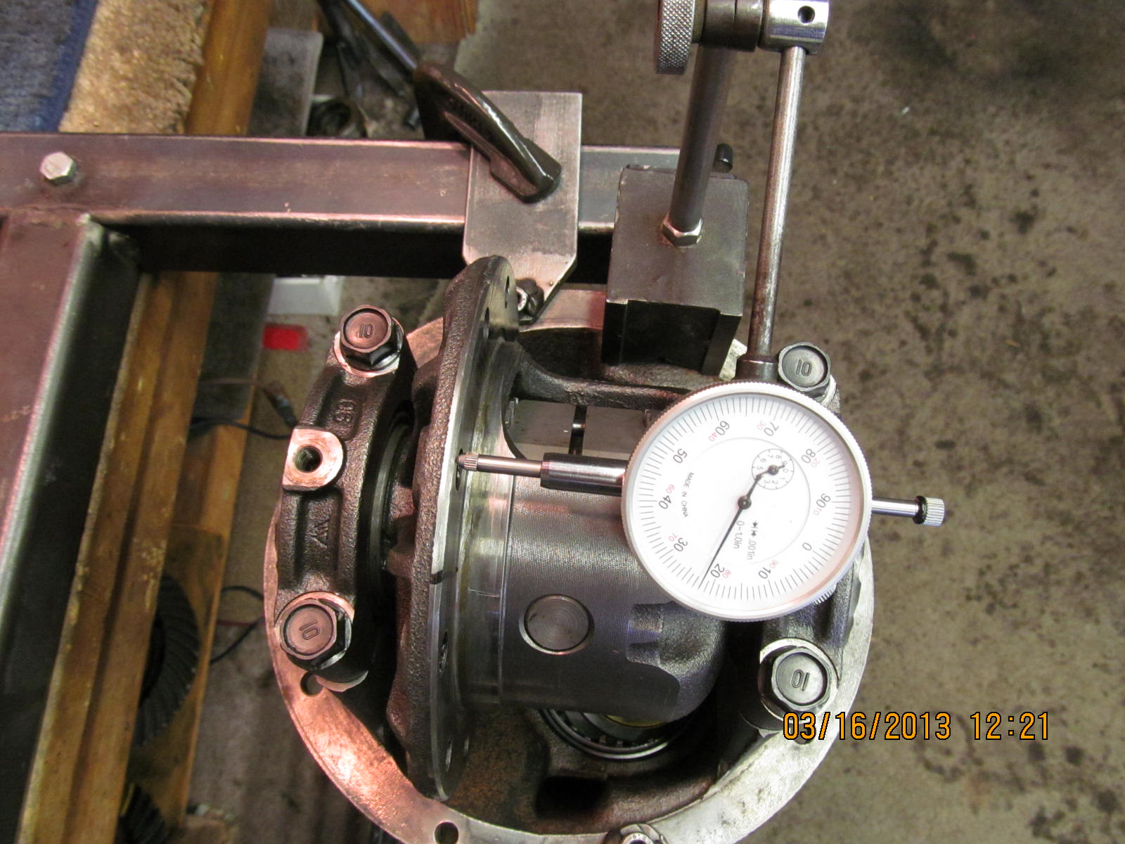
22 thou run-out which is about 10 times out of spec. This case
is un-usable.

I happen to have a spare 4 cylinder case that John could have
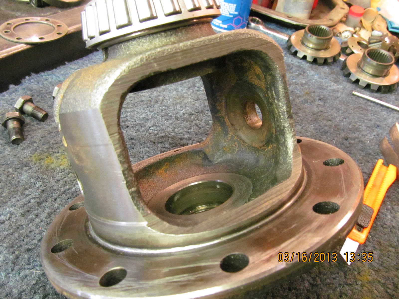
(as seen in the background). It was just a small matter of
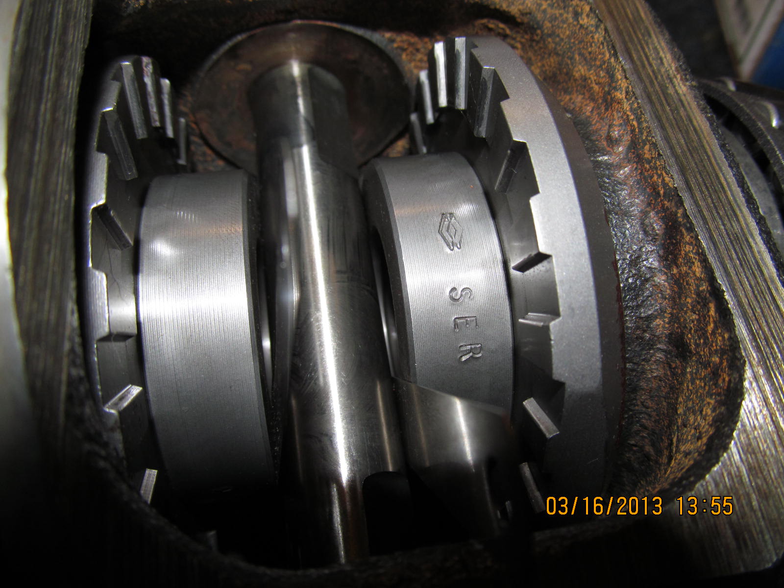
swapping the bearing over and the Lockrite also. These bearings
came off these journals fairly easy.

I wasn't sure if the bearings would be a good press fit on the new
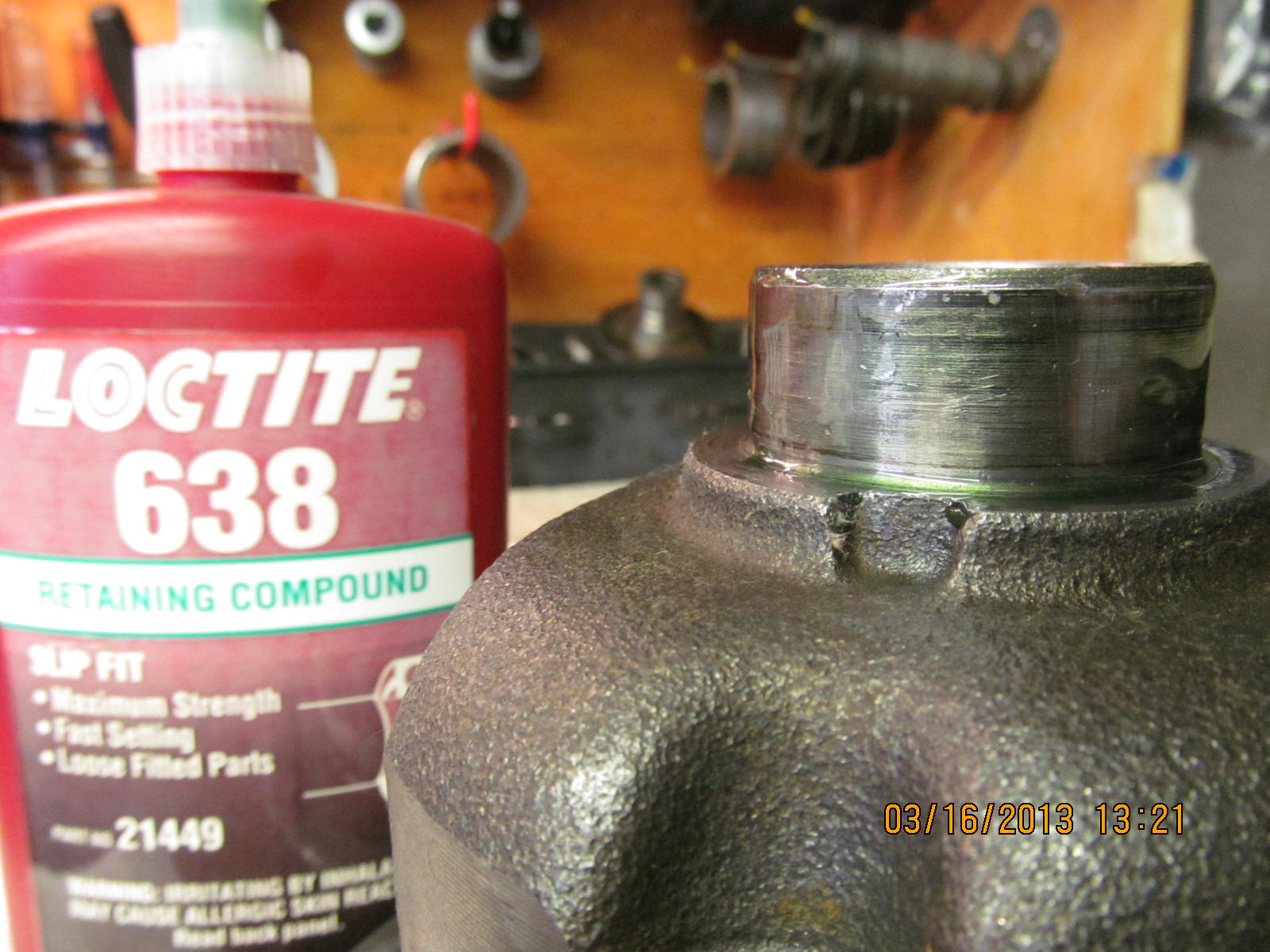
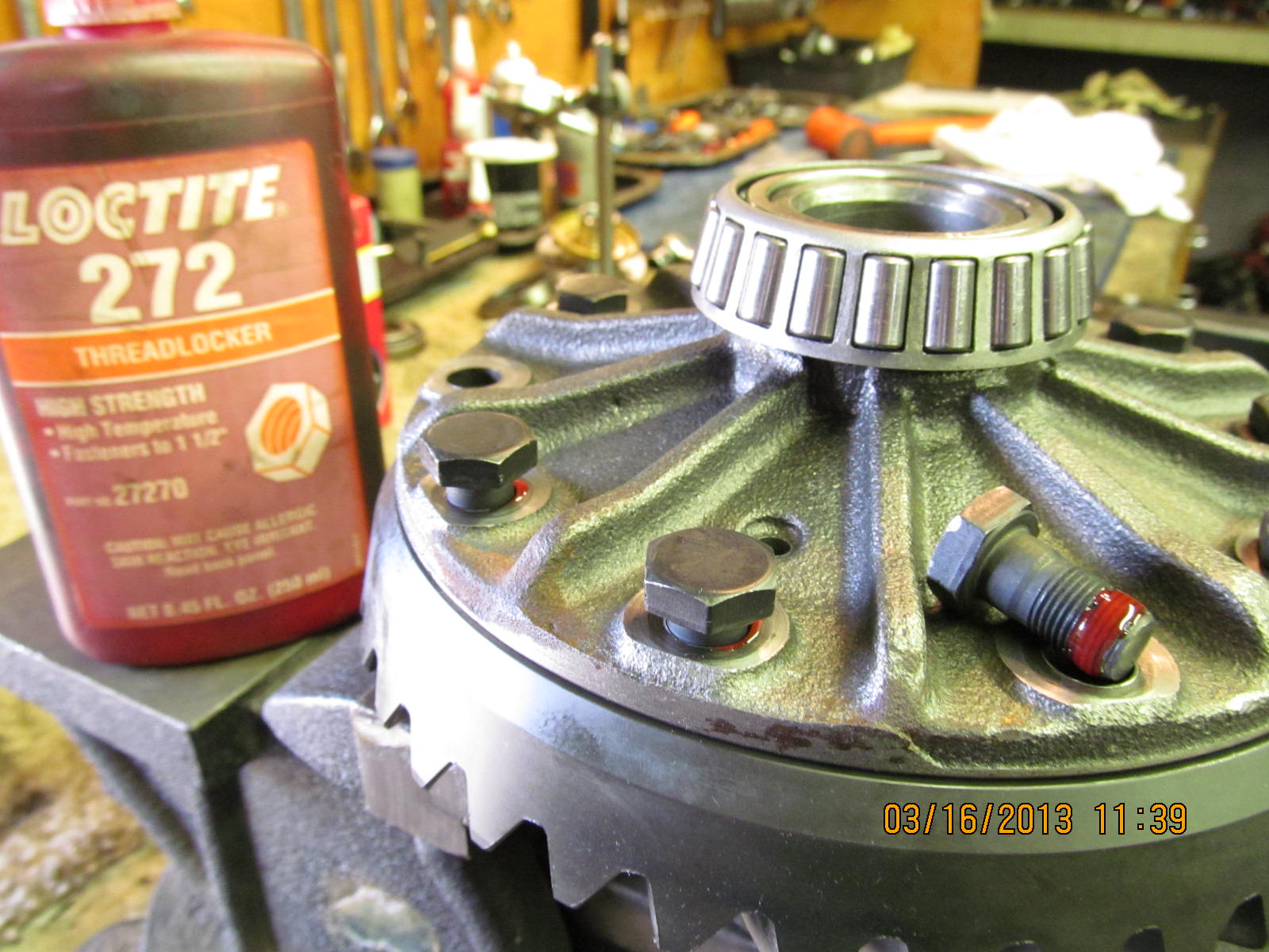
journals so, to play it safe, I cleaned and applied retaining compound.

It's hard to see the green retainer coating but it's there. As it turns
out, the bearings both pressed on very tight which means God help
the next guy that has to remove them :) Consider it extra insurance
that these carrier bearings will never loosen up on the journals
like some of the other 4 cylinder cases.

Now, to remove the spiders and side gears. Use a roll punch to knock
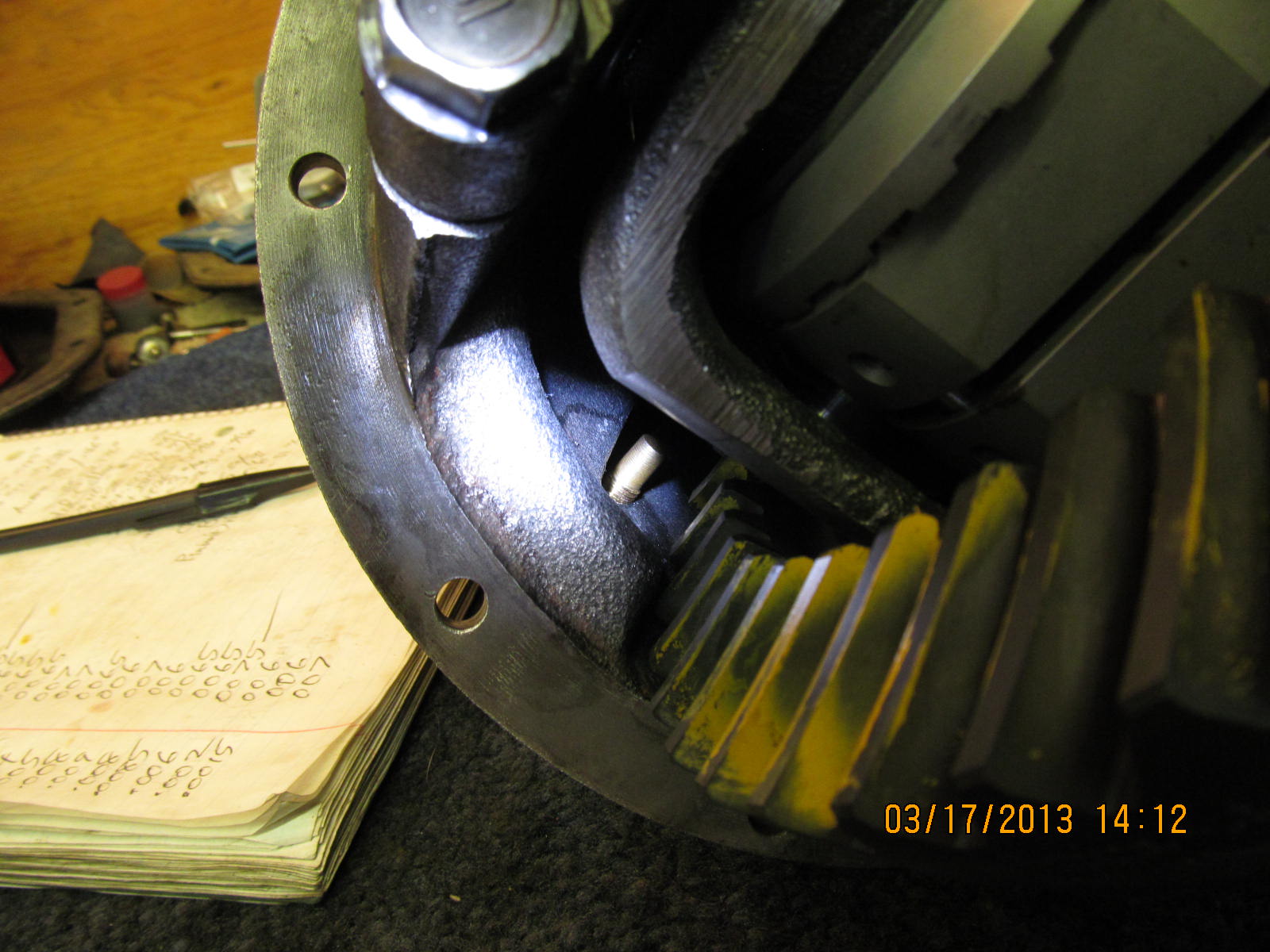
the roll pin out. Easier said than done. Some of those roll pins take
some good hits to break loose. 3/16" or 7/32 diameter punch works
best.

Everything is out...surface was touched up with a file...and a quick
run-out check shows only .001" variation this time.

The Lockrite is now removed from the warped case. Springs actually
came out pretty easy.

Cross-pin removed

One of 2 checks to make sure the Lockrite is in tolerance. Crosspin
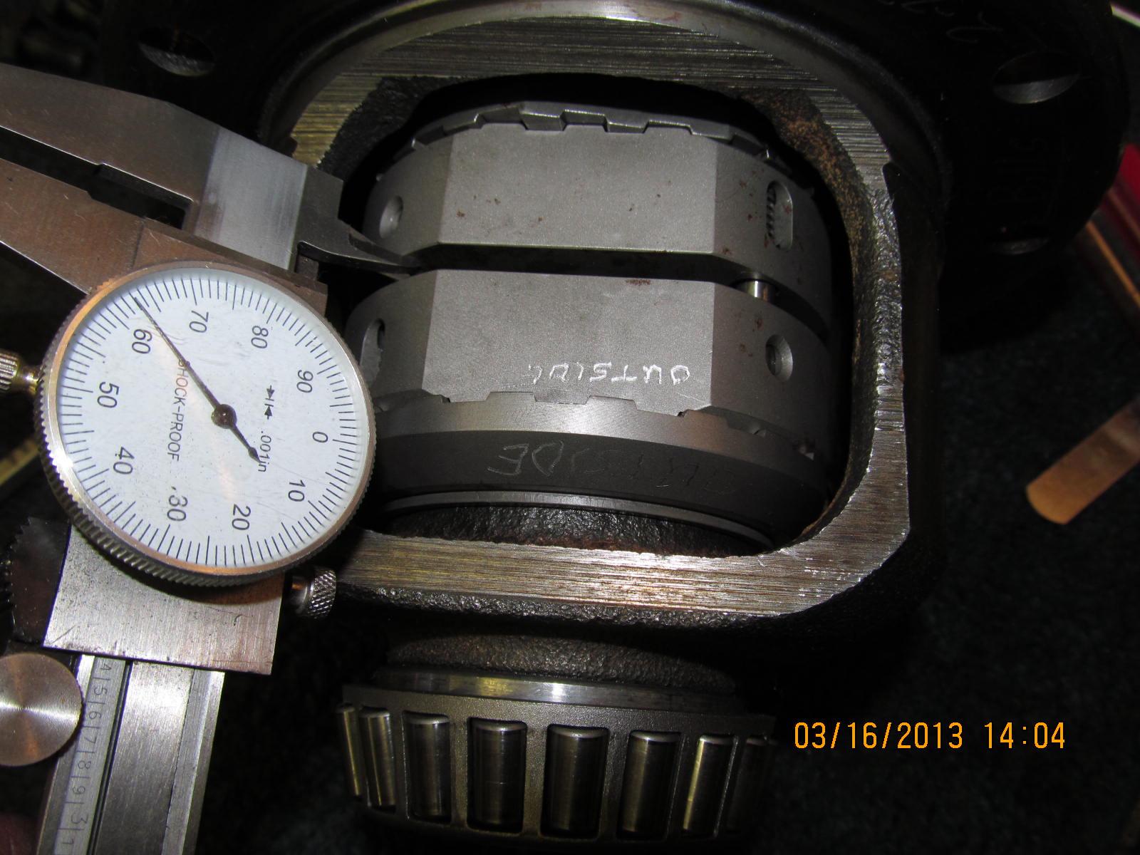
to spacer play. I measured about .010" on each side.
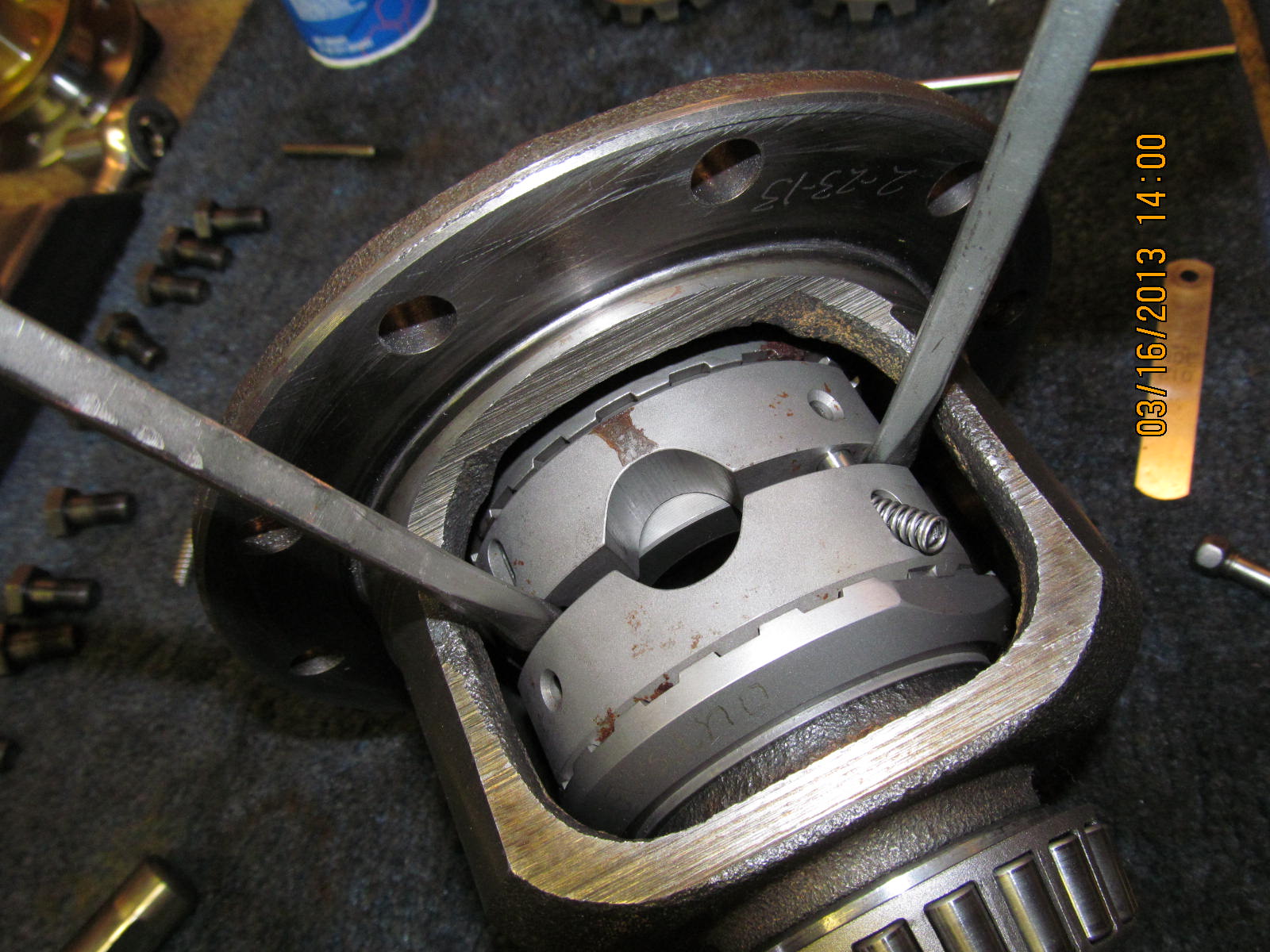
Wedged screwdrivers keep the drivers apart while the springs
are inserted.

The springs popped into place rather easy using a small
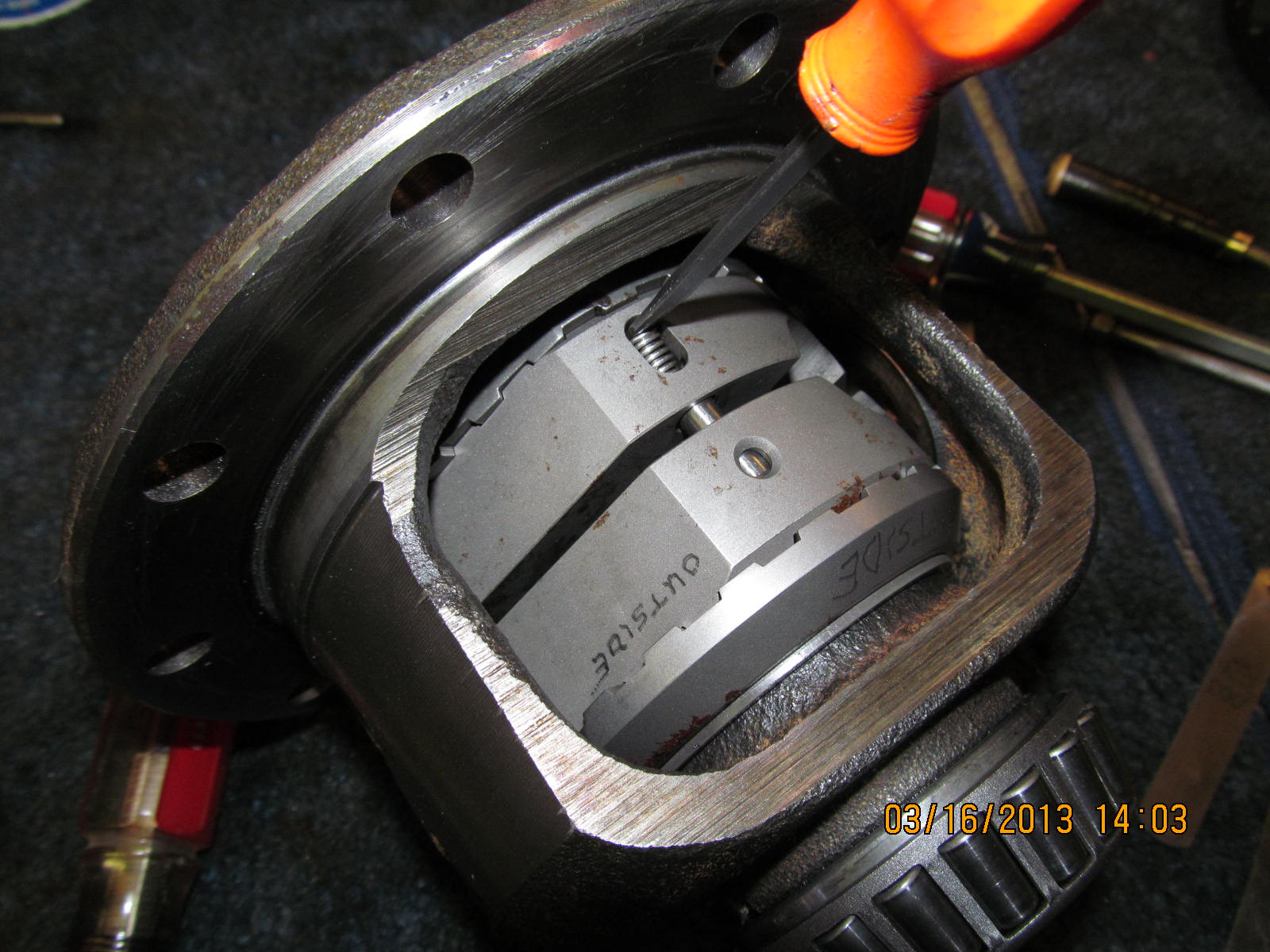
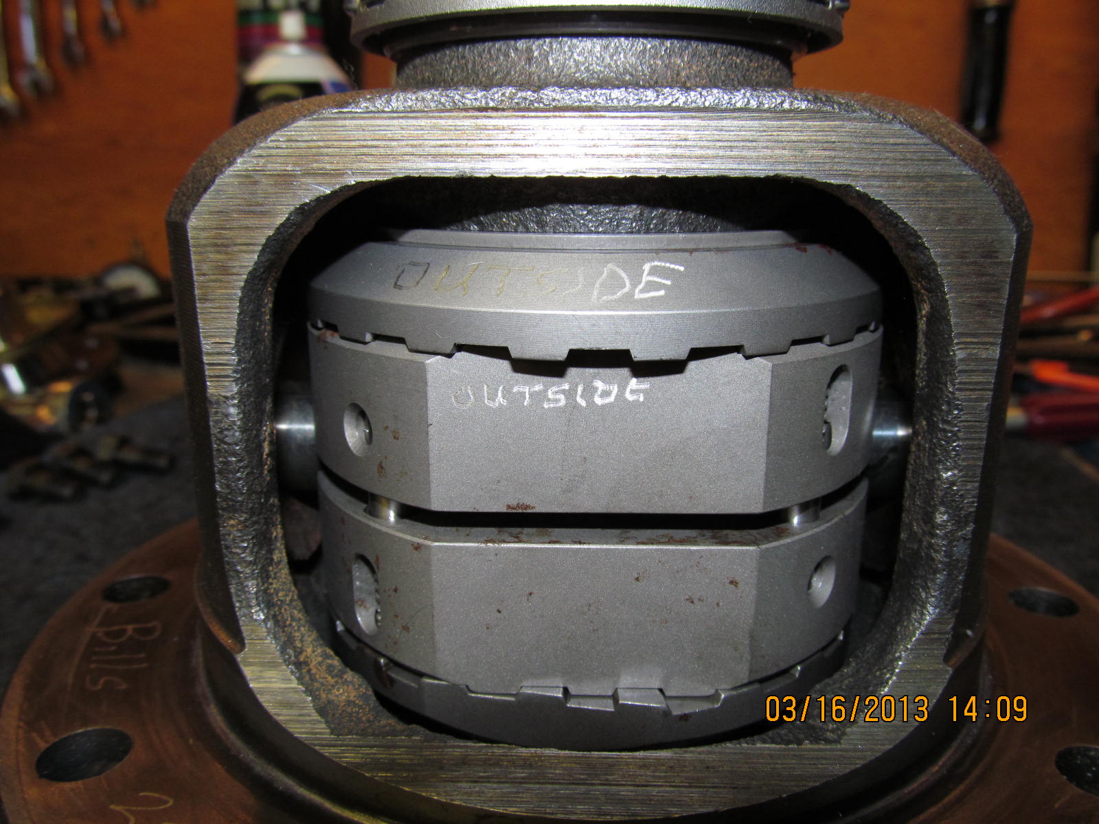
screwdriver. Notice thatI have the outside driver and coupler
marked as outside. The teeth might have developed some
wear on the leading edges and I didn't want to disturb the
wear engagement in this new case.

The second measurement....should be less than .168" and it is.

That's a dimple I made using a center punch to cave in a portion
of the hole. The roll pin will never wander out.

Done. Looks good.

Same thing again...apply a fresh splash of red loctite
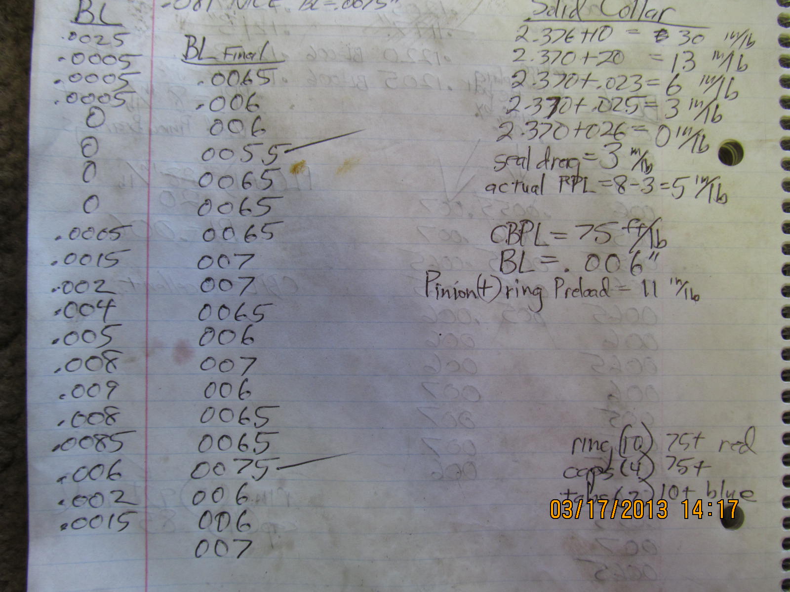
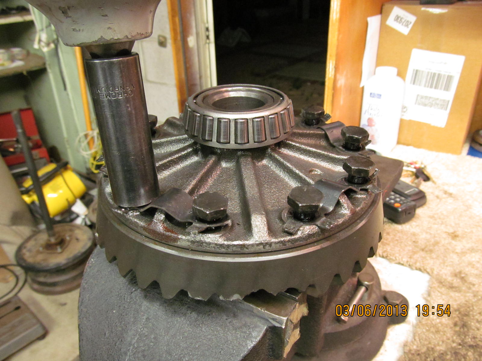
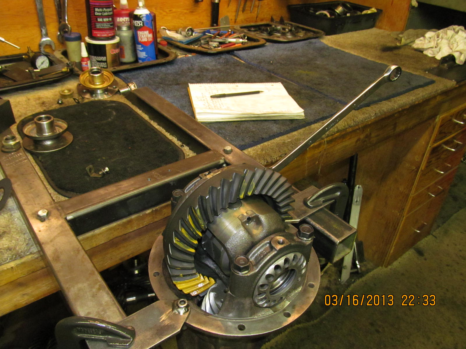
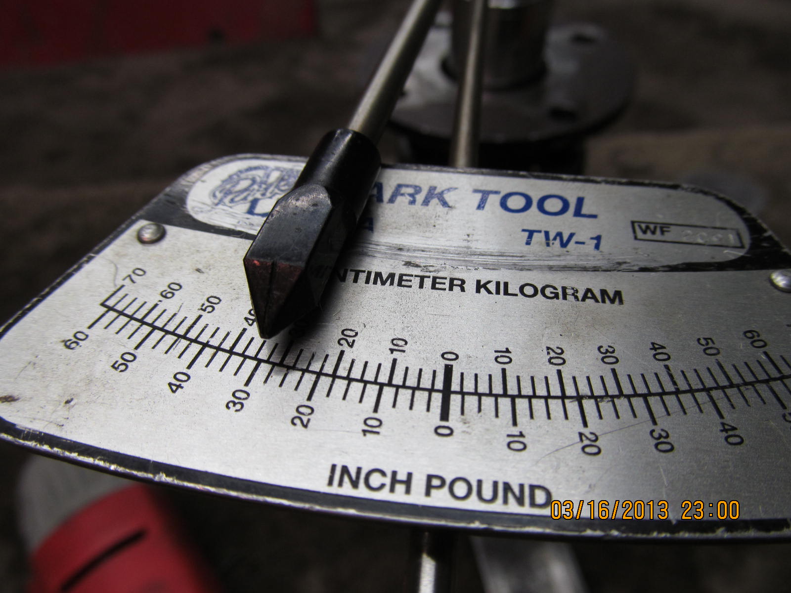
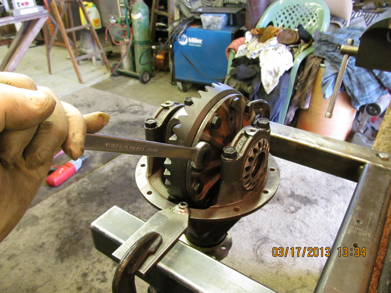
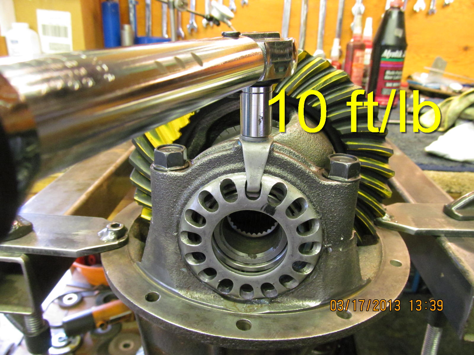
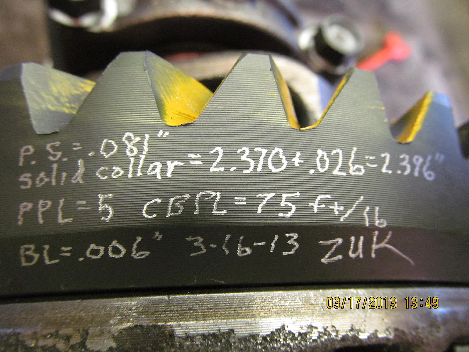
and 75 ft/lb torque.

Backlash is adjusted and this time the variations are almost zero.
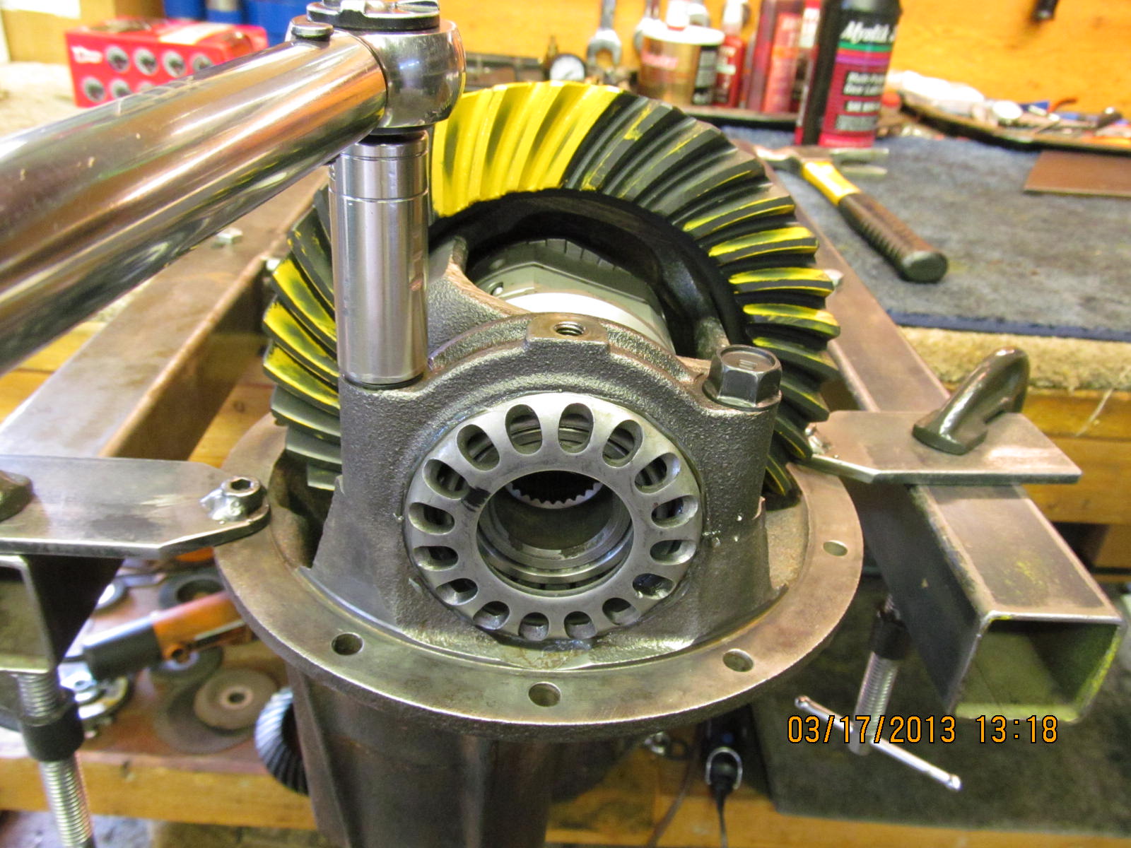
Some carrier bearing pre-load was also dialed in.

The pinion depth shim is still .0785" but I wanted to check the
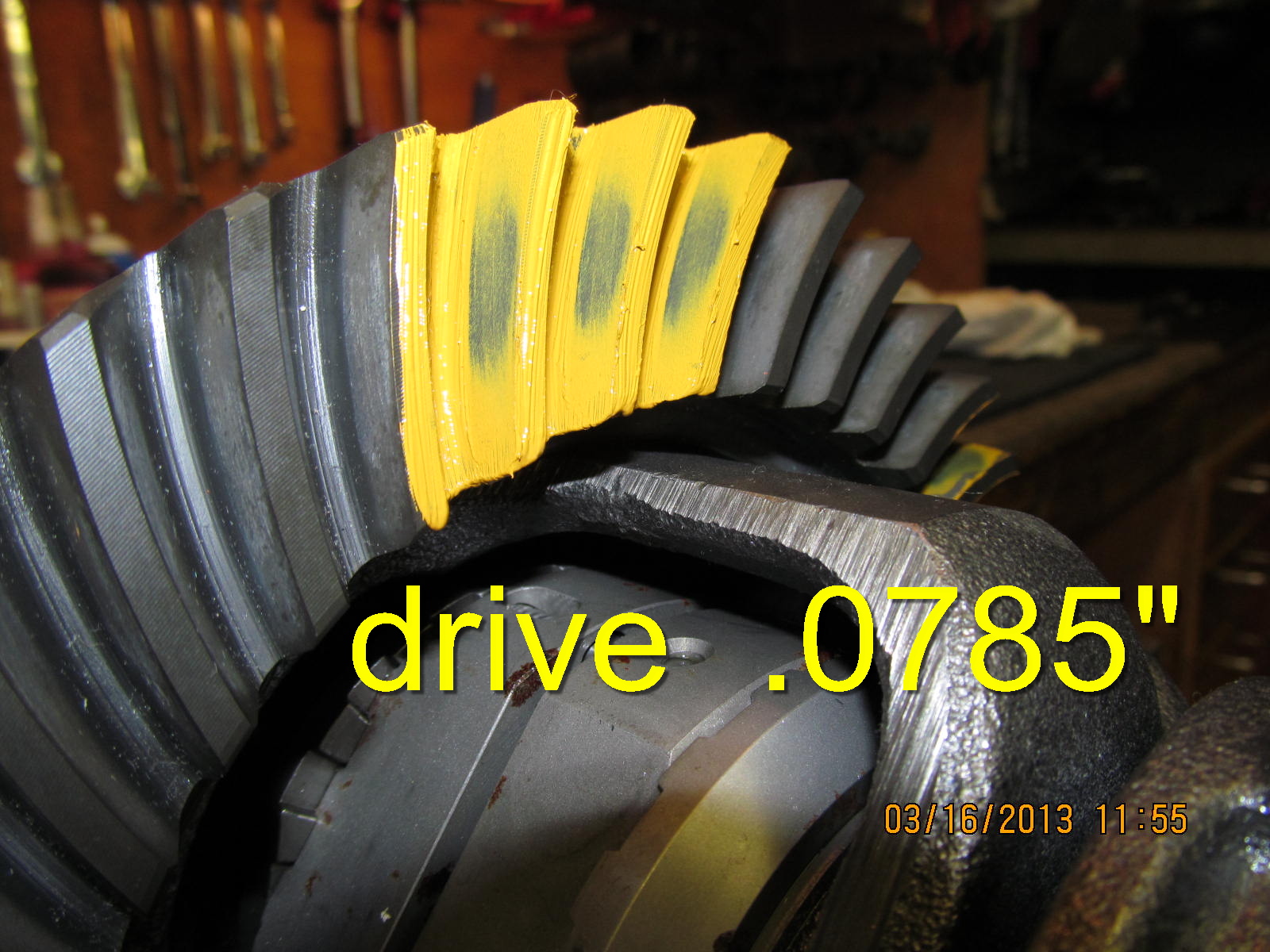
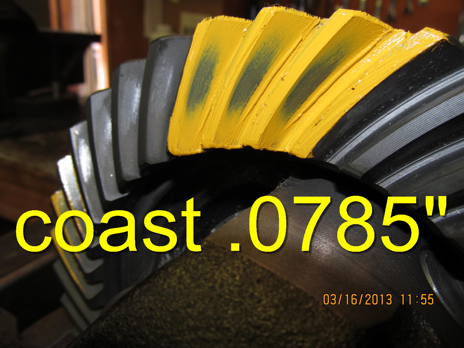
pattern once more. Using a rag to offer some resistance....

...turn the ring gear back and forth perhaps 3 times with a
17mm wrench.

Pattern looks good.

Coast ok also.

.............

Pinion says I can go a little deeper if I want based on the comet
tail tucking into the root so much.

..............

I figure this will be the final setting of pinion depth so might as
well put the solid collar in. This is the Toyota OEM solid collar.

So, first to remove the pinion and change the shim.

Most of the 29 spline flanges are a tight fit. It's more trouble to
remove them but I still wish the all-so-common 27 spline versions
would fit this snug. All you Russian guys that are using the universal
online language translators, I imagine it's hard to understand some
of the English phrases (colloquialisms) that I use :)

Now, press the pinion out.

The OTC-1130 bearing splitter easily grabs the base of the pinion
bearing.

Press the pinion out.

The .0785" shim is replaced with an .081" (.0025" thicker).

At the same time, I will set the shimming on the solid collar to get
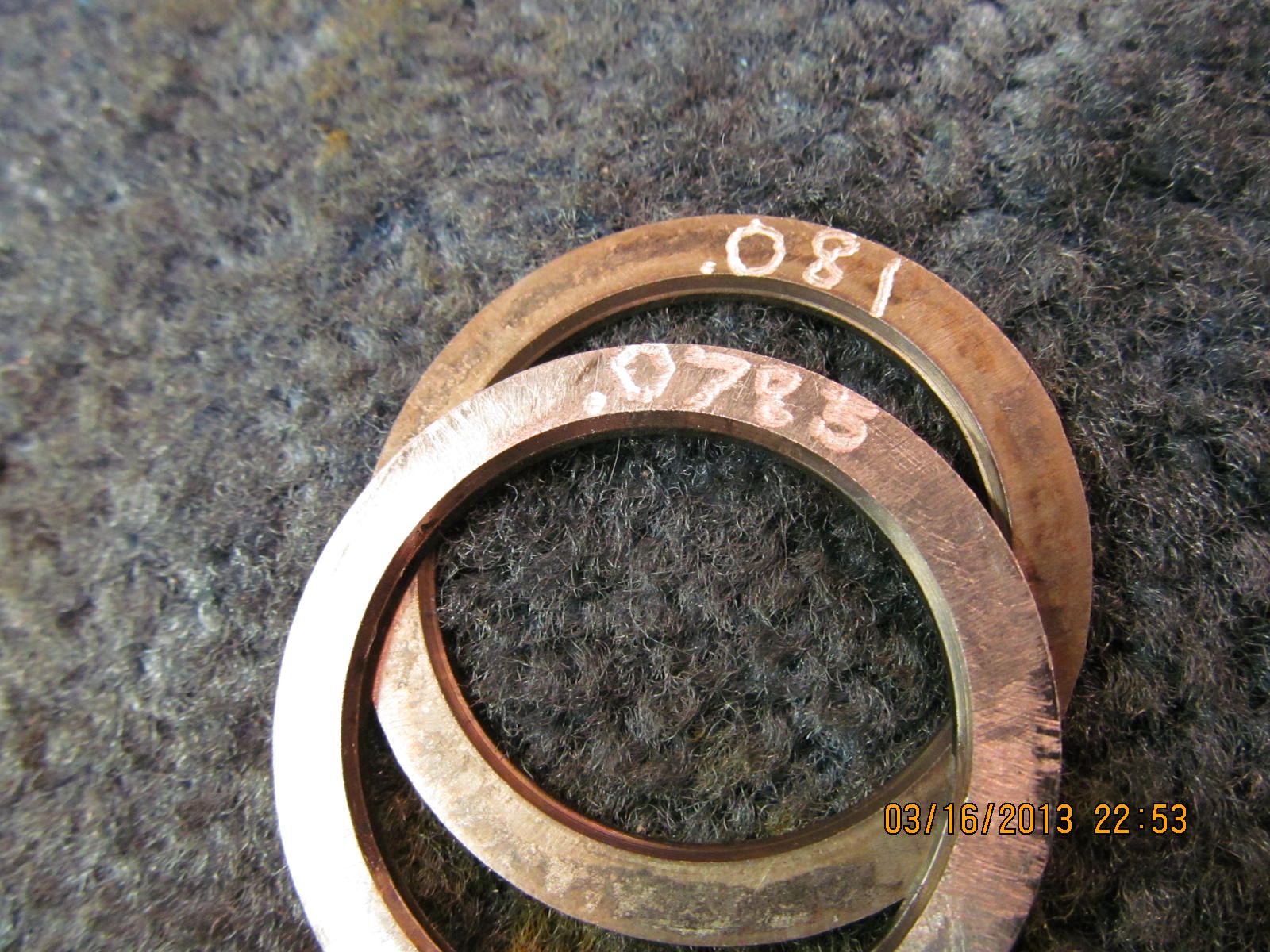
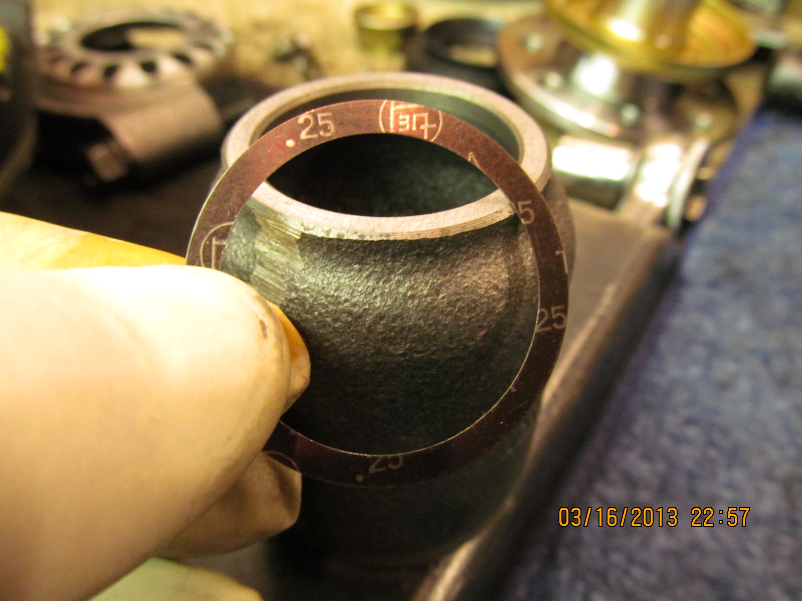
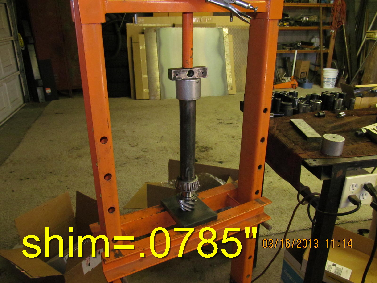
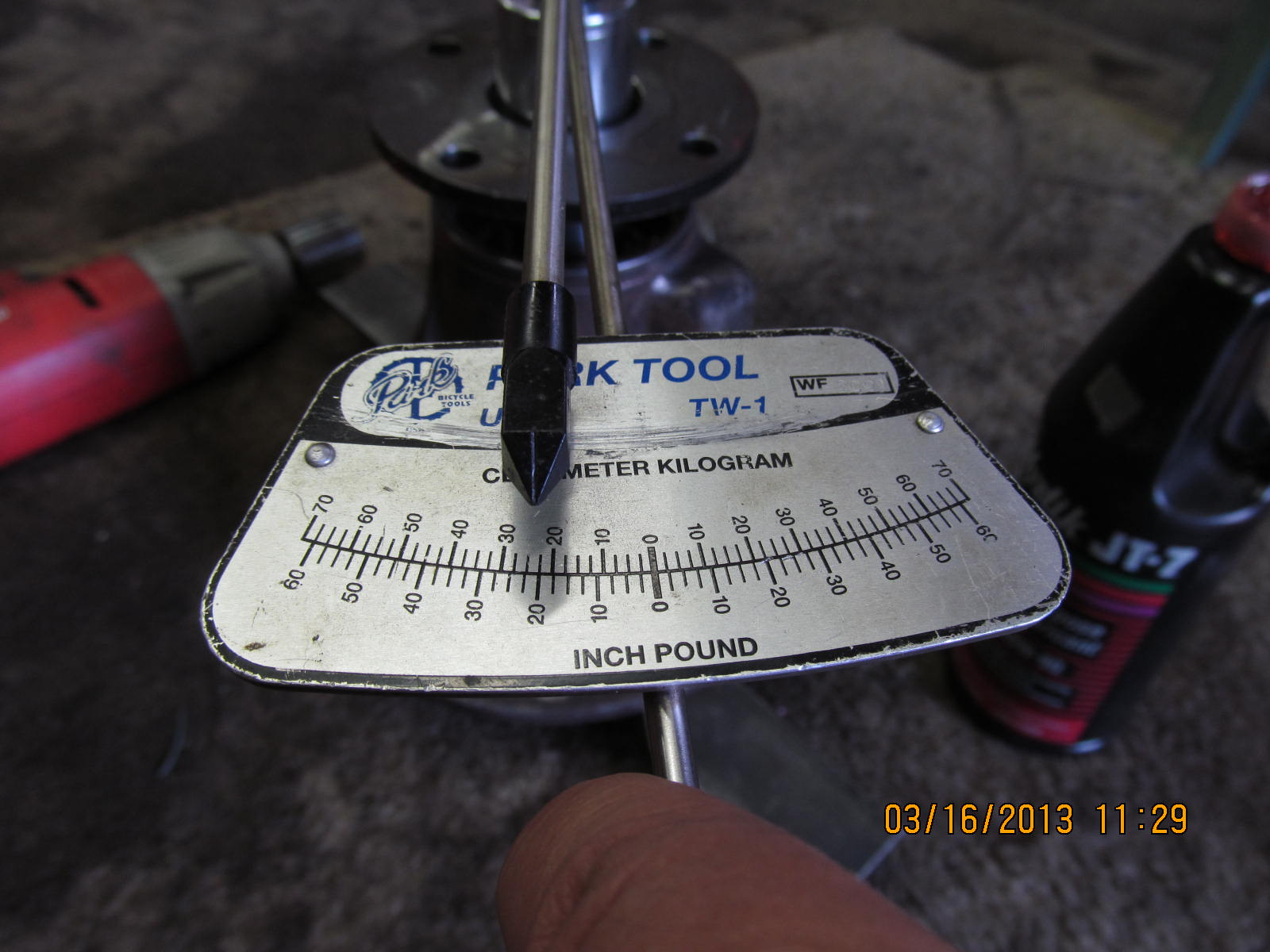
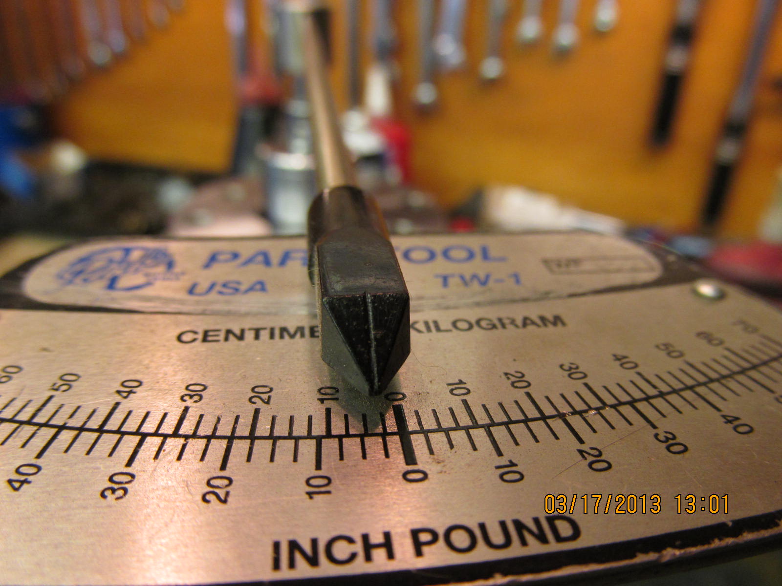
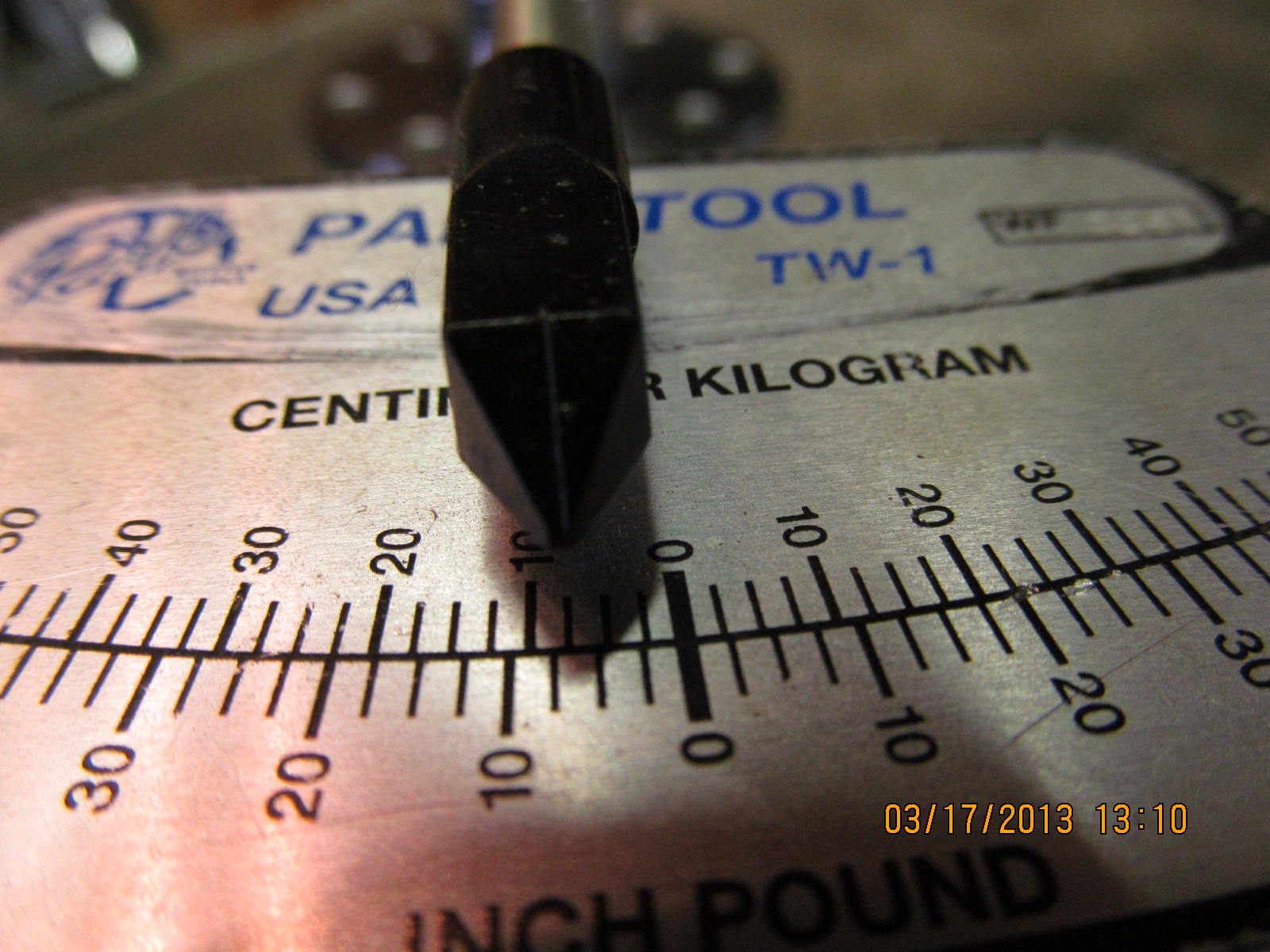
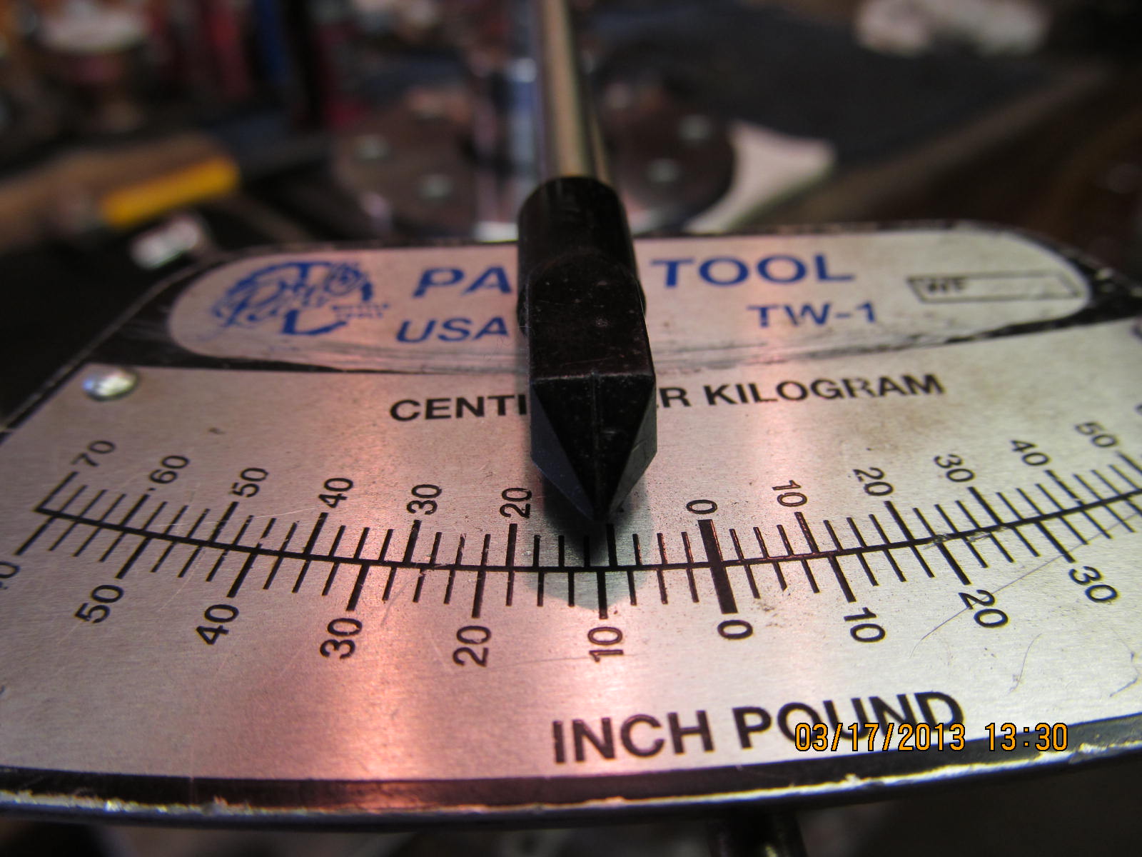
a target 5 in/lb. This one is .25mm which converts to .010".

This time the solid collar is assembled with the pinion.

Using the .010" shim on the collar resulted in too high a pre-load
reading....but for doing a pattern check it's still ok.

That's what I like to see.

good.

................

The tail is just starting to come off the root.

Satisfied with the pinion depth, now to concentrate on getting the
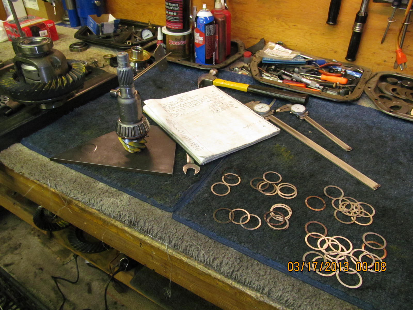
PPL just right. As my notes at the end of this link show, it took
about 5 tries to get it just right. Basically, using the electric
impact to tighten the pinion nut, I shoot for about 0~1 in/lb of
pre-load. Then I can use the 3 foot breaker bar to compress the
molecules in the collar just enough to yield a final 5 or 6 in/lb.
The outer pinion bearing is not brand new so that's the reason for
only 6 in/lb pre-load.

The pinion seal is now installed. This one is rubberized so I really
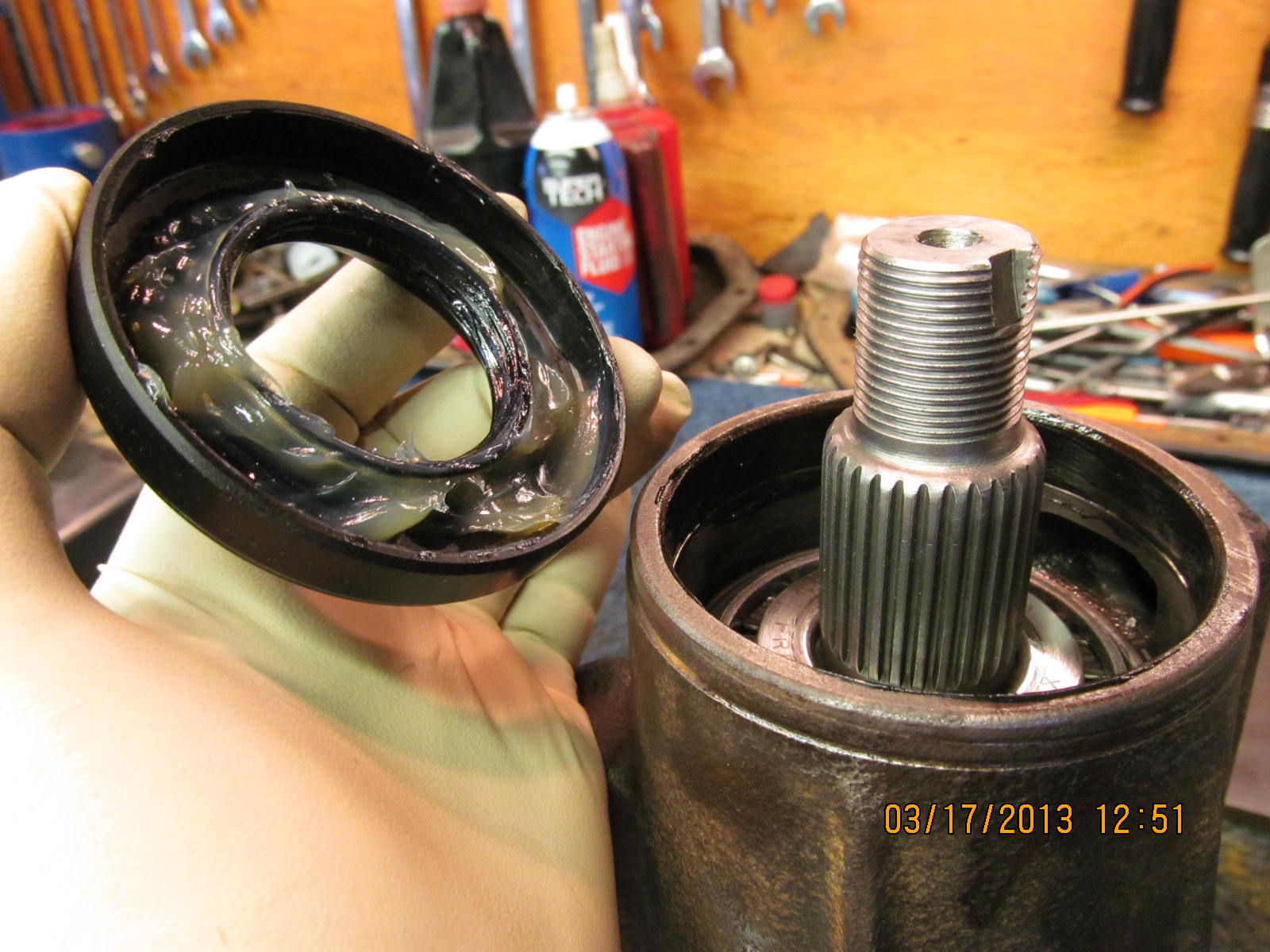
do want to use some silicon rtv to help tap it in place. The grease
keeps the little spring coil from popping off during the hammer
process.

Tap the seal on evenly and flush.

I still use a penlight to verify that the coil did not pop loose inside.

Clean gear oil is applied to the seal and the related flange surfaces.
don't want a dry start-up on the seal lip and, also, I want to minimize
the seal drag caused by the tight fitting rubber lips.

It's just as easy to support the pinion head on the bottom with
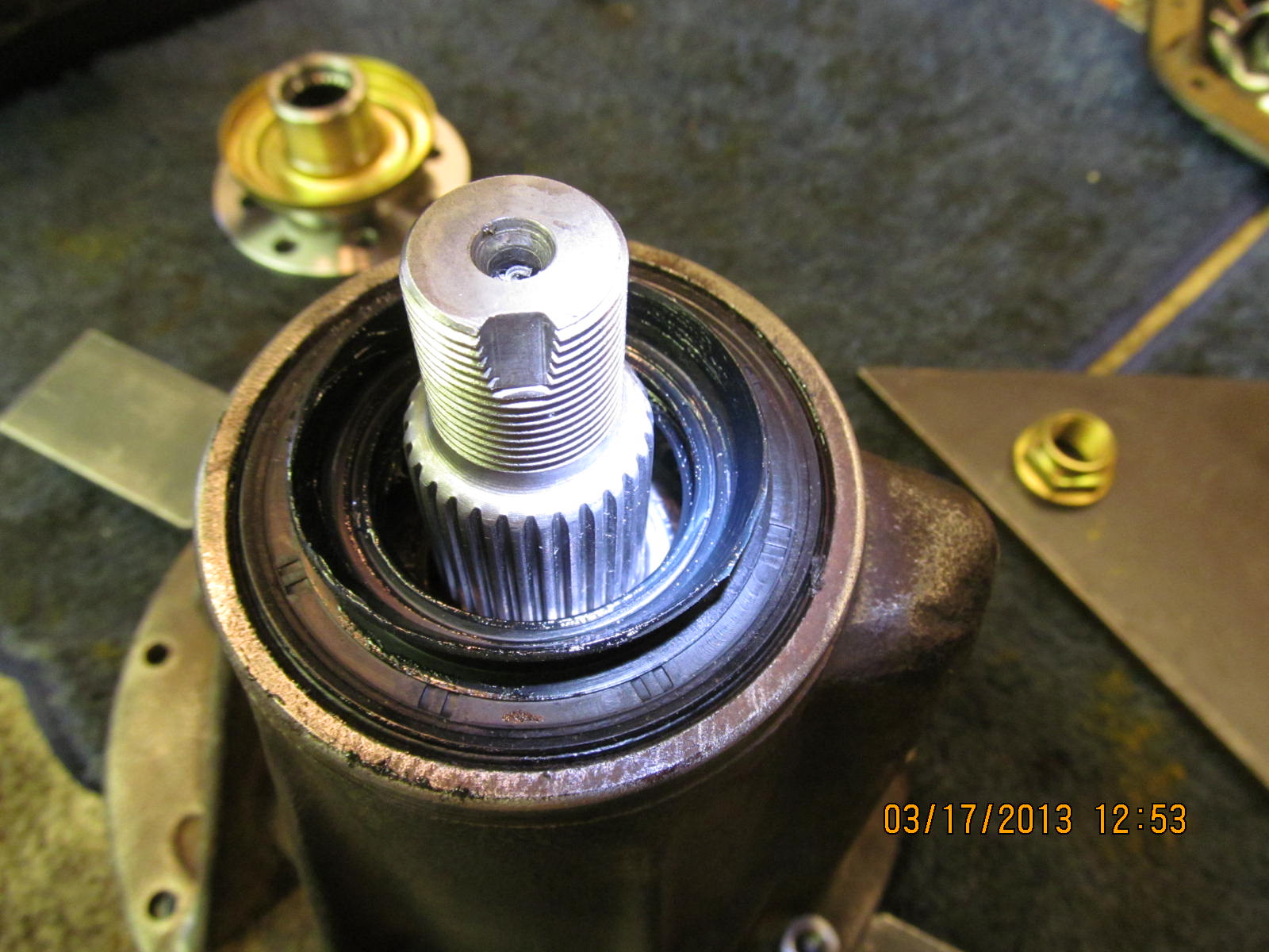
aluminum pucks and gently press the new 29 spline flange in place.

Red loctite and the pinion nut is ready for a real tightening
operation.

Without tightening the nut, this is my measured pinion seal drag due
to the rubber lips...about 3 in/lb.

The flange is soundly secured.

The 3 foot cheater pursuades the pinion nut to give a little more

Turn the flange back and forth while very lightly tapping the pinion
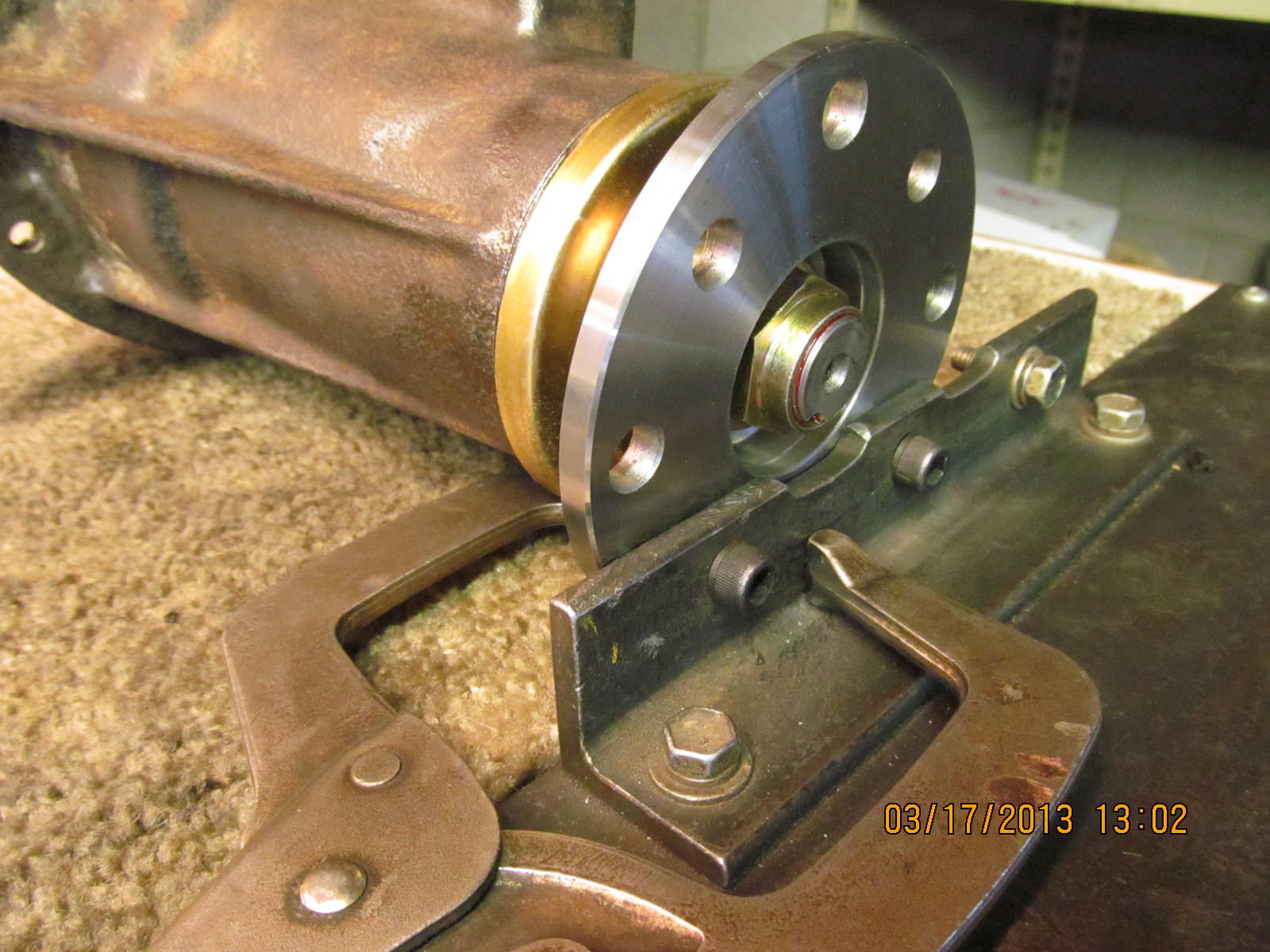
to equalize the pinion bearing tensions. Notice the black sharpie
mark on the edge of the nut. That's how much more the cheater bar
gave me...almost 1/4 turn.

And that 1/4 turn gave me another 5 in/lb....3 was already there due
to seal resistance for a grand total of 8 as shown above.

Pinion end is complete so now to grease the threads for the
wheel adjusters.

I prefer to set the wheel in first and then wiggle the bearing caps
in place til it feels just right...

...then tap down with the rubber end of the hammer. It bangs in
place with a nice solid snap sound and no gap on either end. Then
I'm pretty sure that the threads are all aligned.

Tighten to 75 ft/lb.

I use my favorite spanner wrench tool for tightening the wheels.
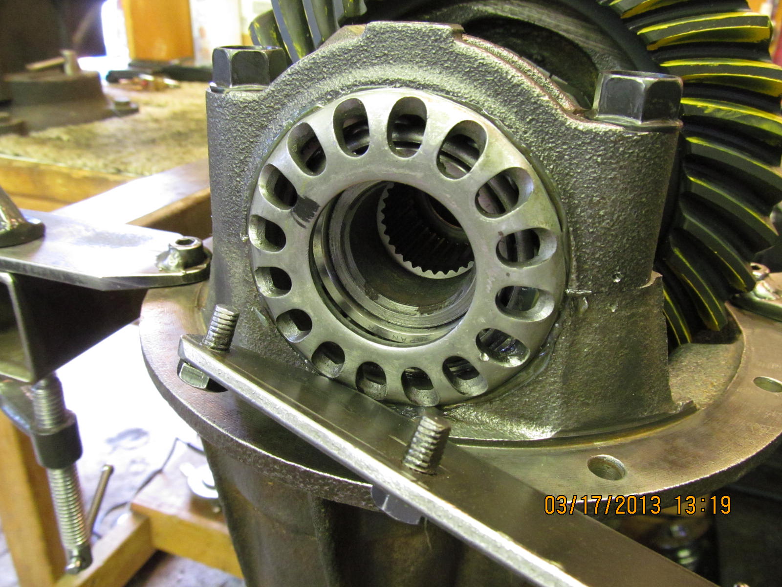
The carrier bearings are used so I don't want to get carried away
and really crank on them. I will aim for 75 ft/lb on both wheels.

I already had some black marks on the wheel so I have a starting
point and it is now easy to tweak the carrier bearing pre-load while
guiding the backlash where I want it. On the ring gear itself, it
specified .006" for backlash.

Bearing tensions are equalized by rapping hard in all 4 corners
like this.

Backlash is now final checked. Excellent...very little variation and
the minimum is right at .006". Checked on every other tooth
...about 20 readings.

Pinion bearings plus carrier bearings results in a total of 11 in/lb.

Don't forget to ding the nut.

Final pattern check. Grab flange and offer some resistance...

...and turn the ring back and forth 3 times.

Right on.

oh ya.

..............

Blue loctite.

Always use 10 ft/lb plus a smidge more.

Information I chose to scribe on the ring.

Date coded.

Getting close to the end but one more thing that John requested...
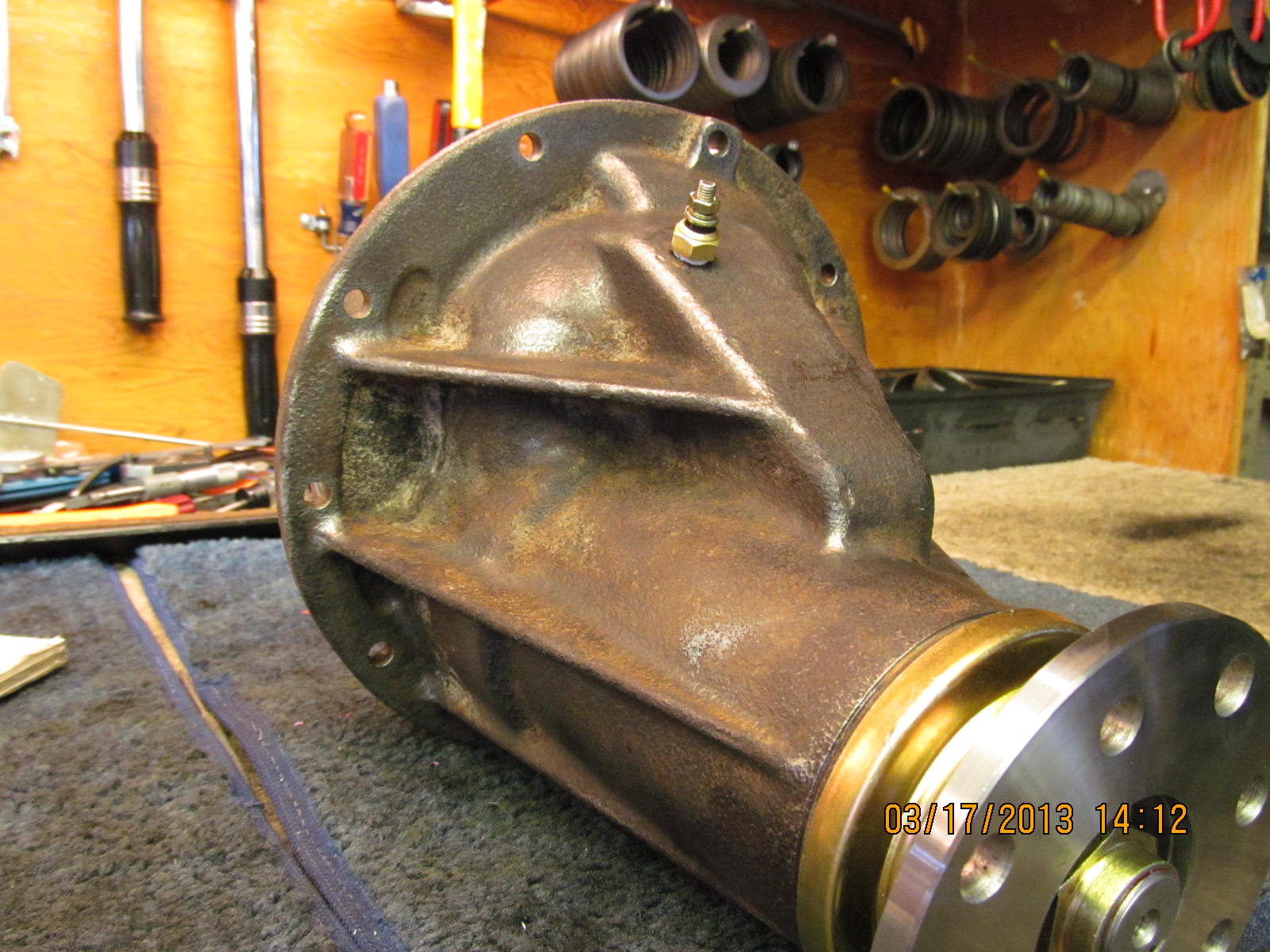
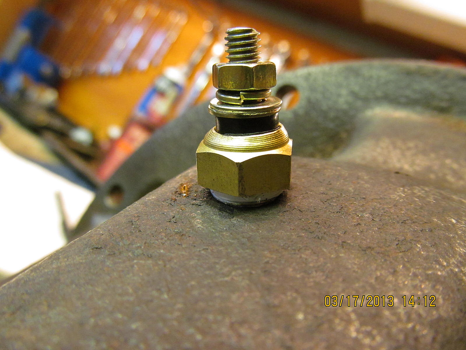
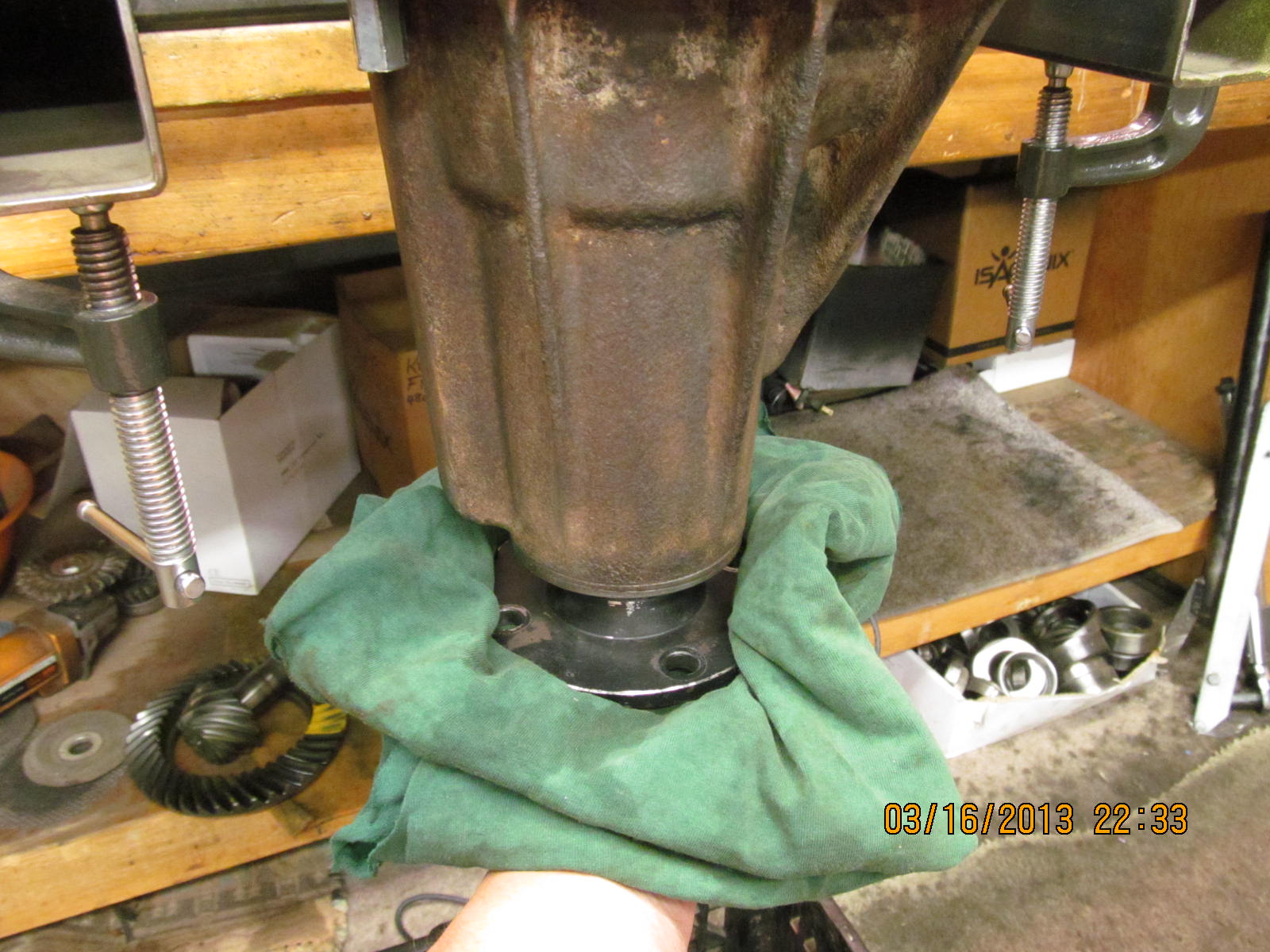
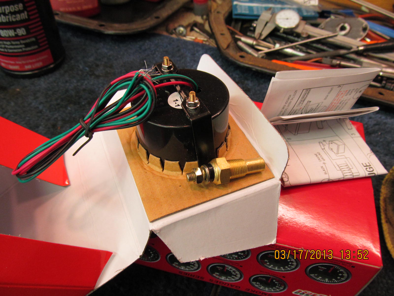
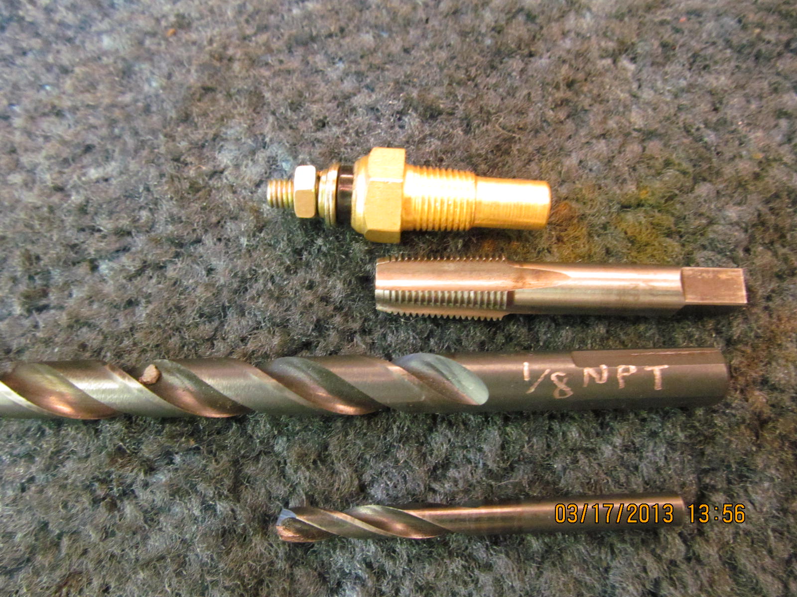
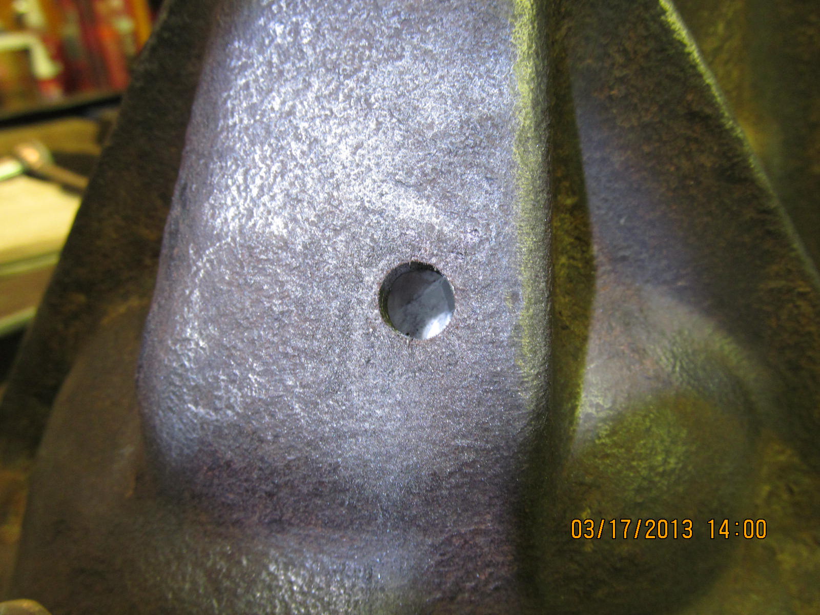
drill and tap the top of the 3rd for a 1/8 NPT sensor so that a
gauge can be used in the cab to monitor gear oil temps. Imagine
the possibilities...a cool break-in of gears....making sure the
gears don't get near 200 degrees F....highway towing.

Gauge plus sensor for $20.66

...................

The hole is drilled. Since I am doing this with the ring gear in
place, a paper towel catches loose metal debri.

Tapped. Note that I left 10 threads showing...tapping all the way
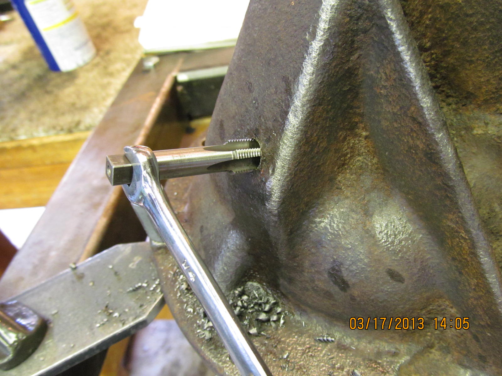
in would results in a loose fitting sensor.

3 wraps of white teflon tape and the sensor threaded in nicely.

My new Canon SX150 sure does a nice close-up :)

The sensor clears everything just fine.

Final notes

Done.