|
|
|
|
|
|
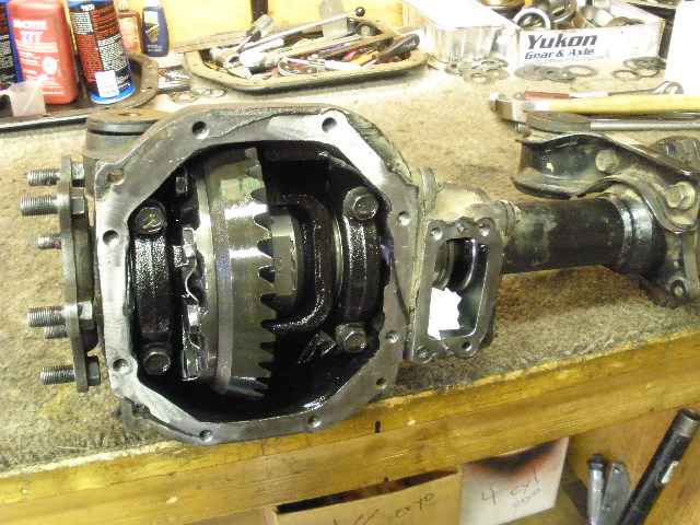
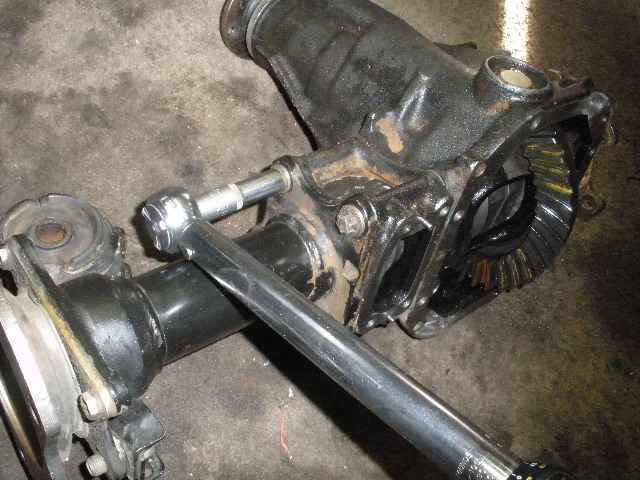
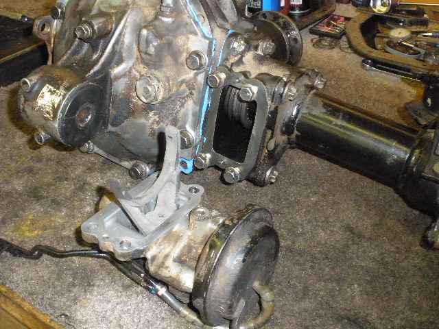
Rick is another local to me and dropped off this front IFS assembly. A Lockrite was recently installed so my task is to give it a general check-up. Rick told me that the installer told him that he had replaced the ring/pinion because they were "all burned up". I have already removed the aluminum cover and the vacuum actuated shift fork assembly. |
|
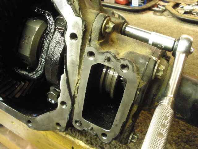
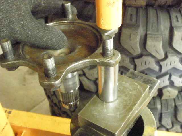
The driverside tube assembly easily pops off after the 4 e-socket bolts are removed. Shown are the 2 short bolts being removed. |
|
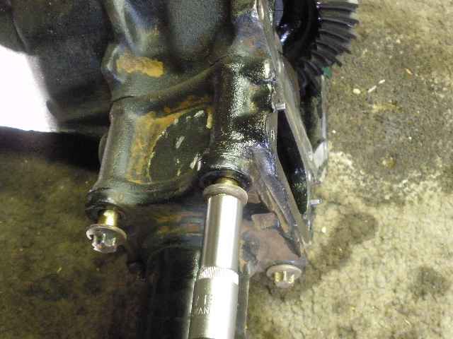
Flip it over and remove the 2 long bolts. |
|
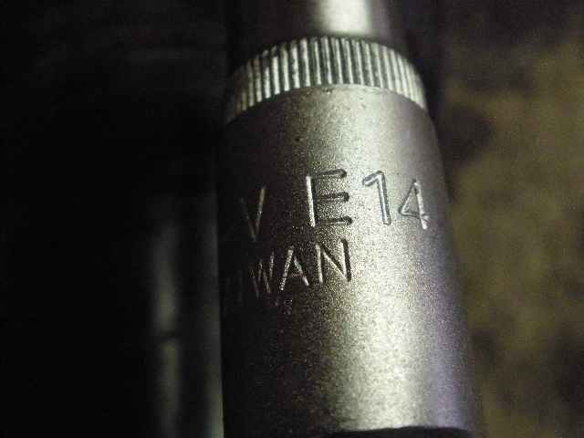
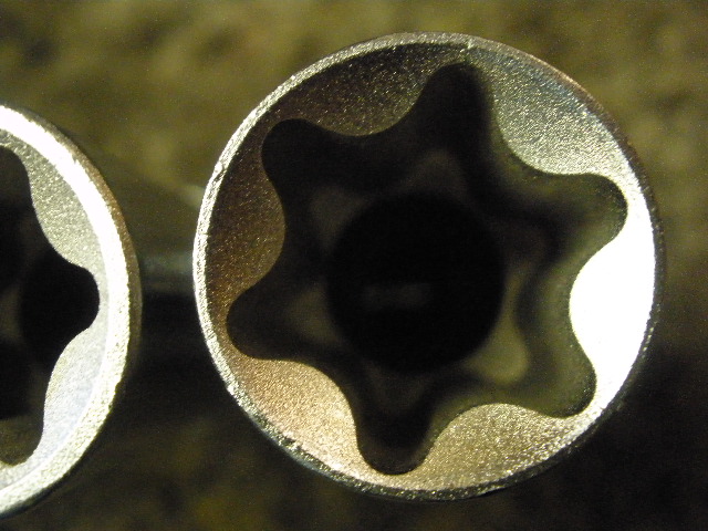
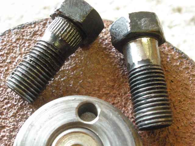
This is the special socket....an E14 size....a 6 sided star socket. I bought these e-socket sets from harborfreight for about $20 total and it's money well spent. Those bolts are on tight so, although it might be possible to force fit (with a hammer) a 12 point standard socket on it, there's also a good chance of rounding the edges off and damaging the bolthead and the socket. One of these bolts was rounded off because the last guy tried to make do with the wrong tool. The other 3 were undamaged so he must have located the proper e-sockets. |
|
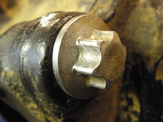
Here's what a good one looks like. |
|
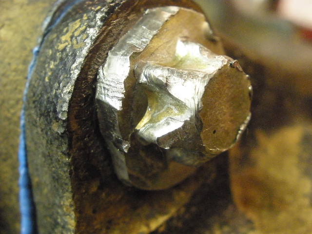
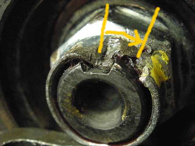
Here's what a bad one looked like. I did the damage to the outside washer area myself....I used a dull chisel to tap around the outside to break it loose and it worked....some of the washer went bye-bye but that's ok. |
|
Here's a pic of the e-socket. |
|
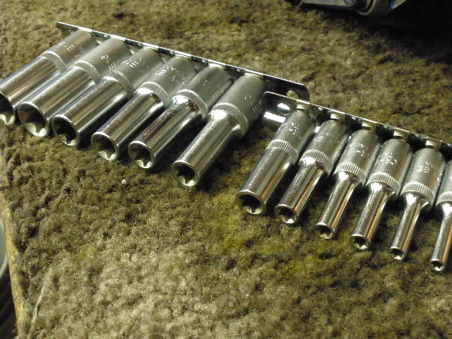
Finally, the 2 e-socket sets I bought at Harborfreight. |
|
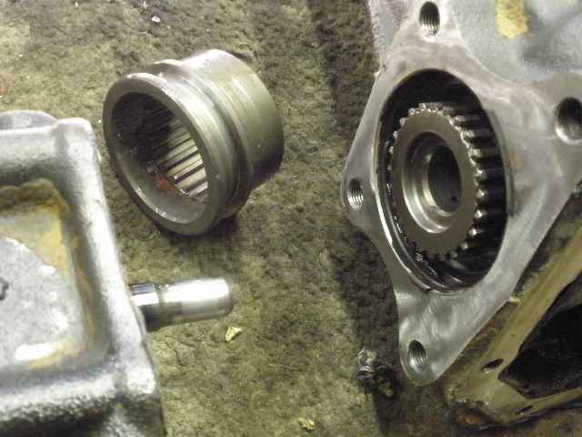
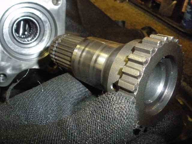
With the 4 bolts out, the only thing holding on the long axle tube is some black RTV. In the middle is the coupler that slides with help from the shift fork for 4WD. |
|
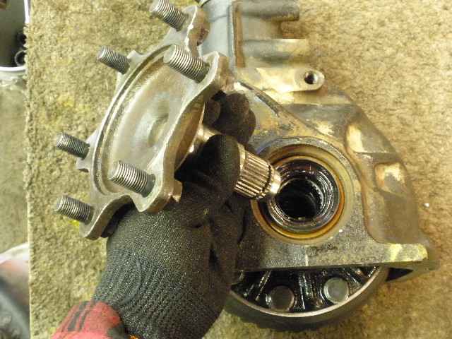
The short axle stub comes off easy with 2 large screwdrivers. |
|
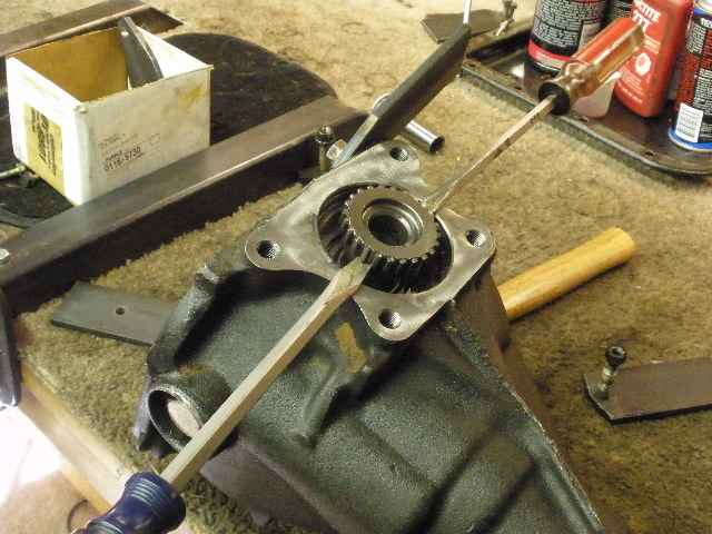
The other side pops off just as easy with the same screwdrivers. |
|
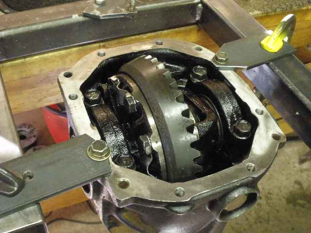
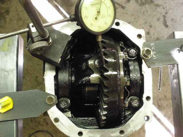
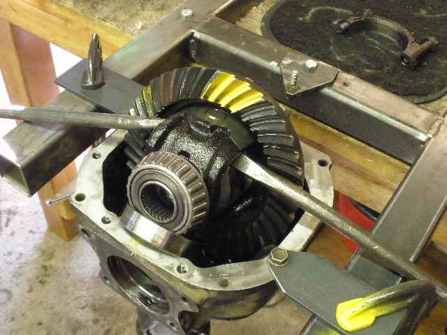
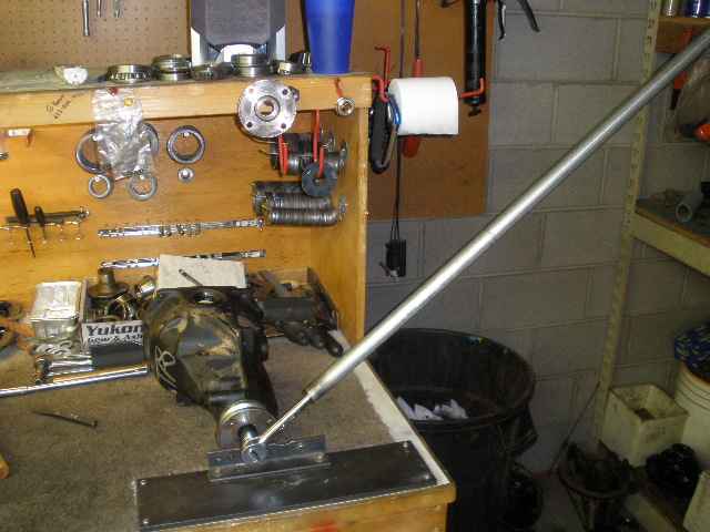
Now the carrier can be secured to my jig. |
|
Backlash was amazingly consistent at .006" around the ring. |
|
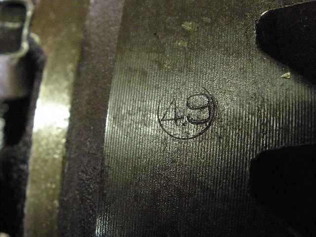
This was the only marking on the ring..."4.9" is the marking found on the factory 4.88 gear sets. These gears are not "burned up" in any way....and they have not been replaced as was told to Rick. |
|
CBPL seemed very good...no need to add thicker carrier bearing shims. |
|
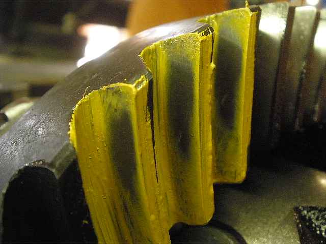
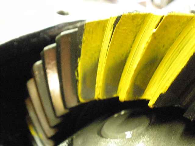
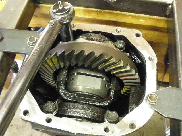
A quick paint of the pattern shows the drive is the proper depth and favors the heel a little. |
|
Coast pattern has good depth and favors the toe heavy. It's desirable to have heavy toe on this front end application. |
|
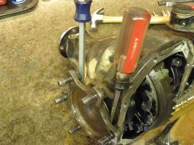
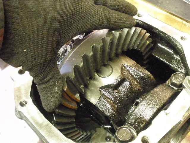
With considerable effort, the use of 2 crowbars broke the case free. |
|
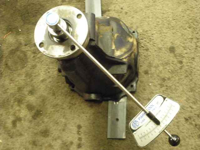
With the case out, now the PPL could be accurately measured. I noted that the flange turned very smooth indicating that the pinion bearings were in good shape. PPL was less than 1 inch/pound. |
|
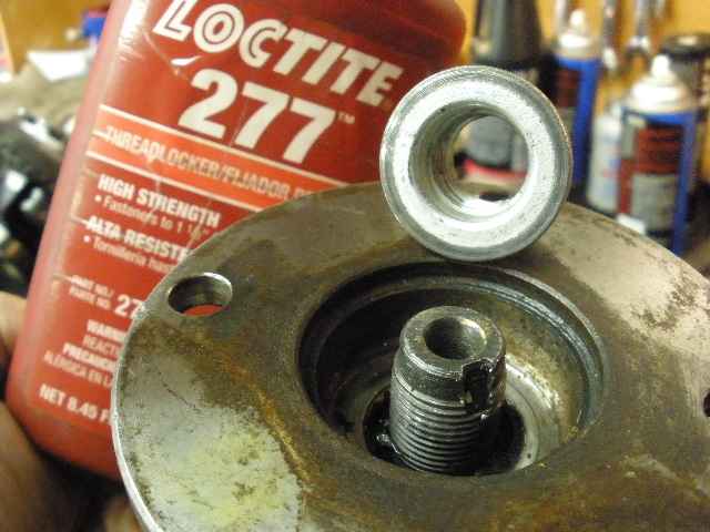
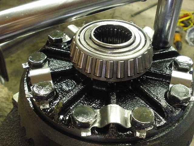
Not visible on the nut here but by the looks of the indentation, it appears that the nut had been removed before probably to replace the seal. I am removing the nut only to add red Loctite and increase the PPL a little. Removing a nut that has a crush sleeve under it is perfectly acceptable AS LONG AS the nut is re-positioned to the same indentation as before or it can be positioned after the indentation to increase the PPL to an acceptable number. |
|
It took leverage to crush the sleeve a bit more to bring the PPL up to 3 inch/pounds....a good number for used bearings. |
|
The red Loctite will keep the nut from backing off. The end of this nut has seen better days but I still staked it in it's new position even though it's not needed with red on the clean threads. Notice that it was been tightened about 1/4". |
|
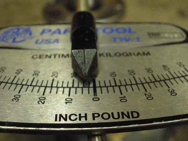
The torque wrench shows that I now have a nice 3 inch/pounds of smooth drag. |
|
These re-used tabs will go in the garbage. I will use red Loctite on the threads. |
|
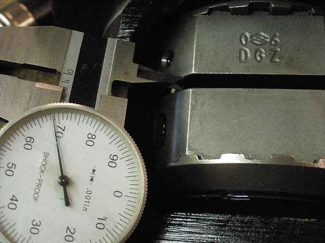
With the ring gear off, now I can get the calipers in place to measure the clearance on the Richmond Lockrite. The double diamond insigna is a Richmond trademark. I measured .168" which is the upper limit and is ok. |
|
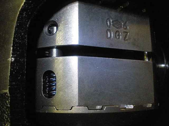
The pins and dual springs looked in good shape. |
|
Loctite and 75 ft/lb. Carrier bearings are used and look good...roller needles inside the journals looked ok also. |
|
The case was a tight fit into the carrier and took a good amount of pounding with the lead filled rubber hammer. The 4 cap bolts were tightened to 75 ft/lbs. |

|
Just a quick look at the needle bearings. |
|
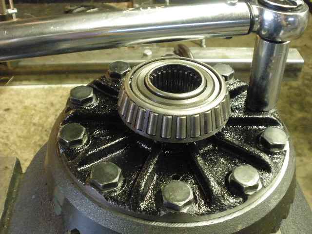
Before this axle flange goes in...it's a good time to remove the 6 bolts. It's much easier to re-install this bulky heavy carrier and get it in place under the truck if those 6 pesky bolts are removed now. |
|
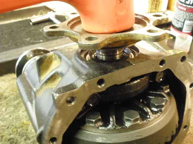
These bolts are not pressed in very hard. I used a press here and it to almost no effort. A sacrificial nut on the end and a small hammer works better actually. |
|
I used a sanding wheel to feather off the serrations. I switched to a thin cutting wheel and it worked better for me. |
|
Now I can tap the flange in. By the way, I am told the Toyota part number for the little c-clip that holds this stub in place is 90081-52006.
The part number for the seal is 90311-35032 verified.
|
|
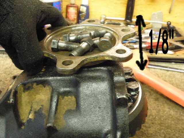
There's about 1/8" of up/down play and it has play in the left/right direction, too. Seems like every flange I've seen does this. |
|
This side does not get a seal...the gear oil must get to the 4WD shifting fork somehow. The seal is on the other side of the fork. |
|
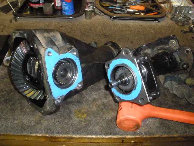
RTV is applied to both surfaces and now it can be bolted together. |
|
These massive bolts are the same thread as the bearing cap bolts so I used 75 ft/lb as the clamping force. The FSM shows 65 ft/lb. |
|
... |
|
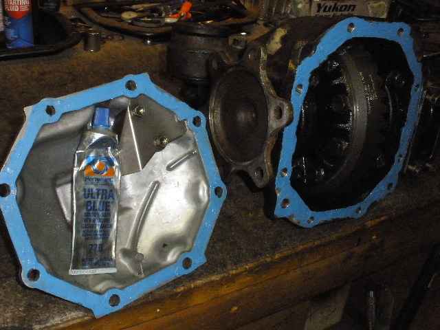
Ultra-Blue rtv dabbed on both halves...and 40 ft/lb on all the bolts. |
|
I left the shifting fork assembly off. I figured Rick might want to find a way to keep the fork in the locked position all the time since he has manual locking hubs now. |
|
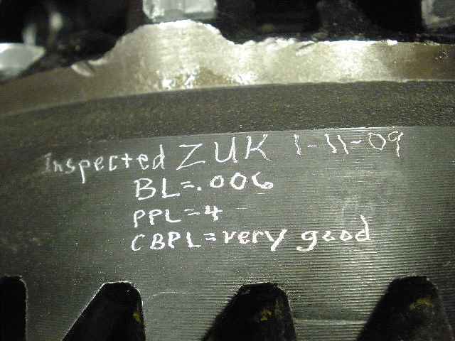
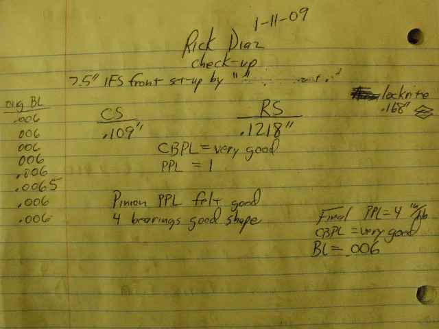
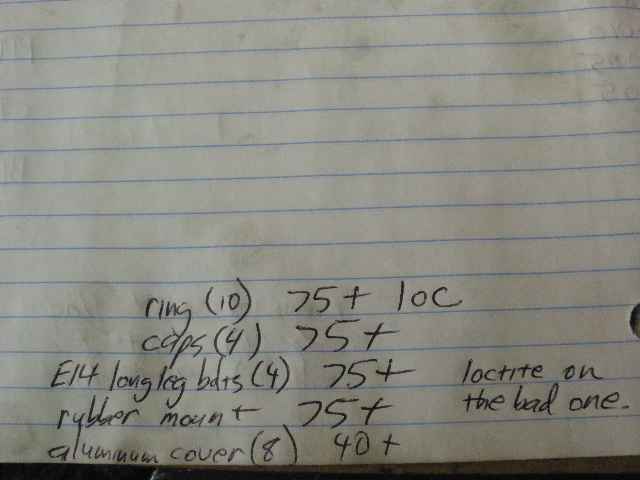
Notes I kept during the check-up. |
|
Done. ZUK |

|