|
|
|
|
|
|
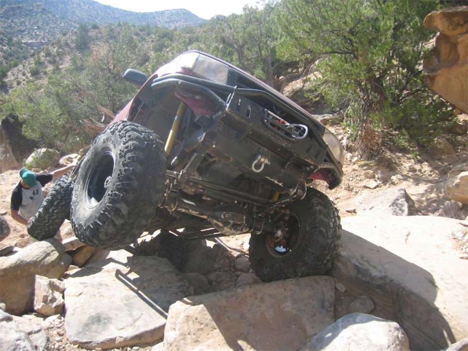
I'm starting to use larger sized pictures (950x713) for greater picture quality and detail so it might take a bit longer to fully load all 52 in this link. Picture above is from year 2005 of Shane on the Coyote Canyon Trail south of Moab near the BFE area. |
|
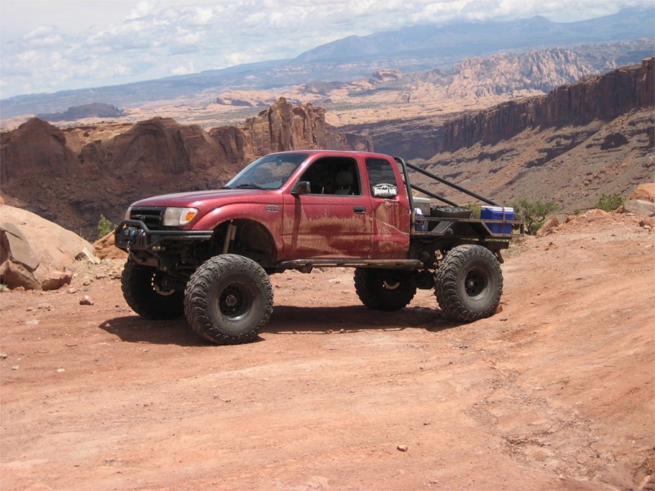
Moab, Utah in 2009.....somewhere's at the top of Pucker Pass. |
|
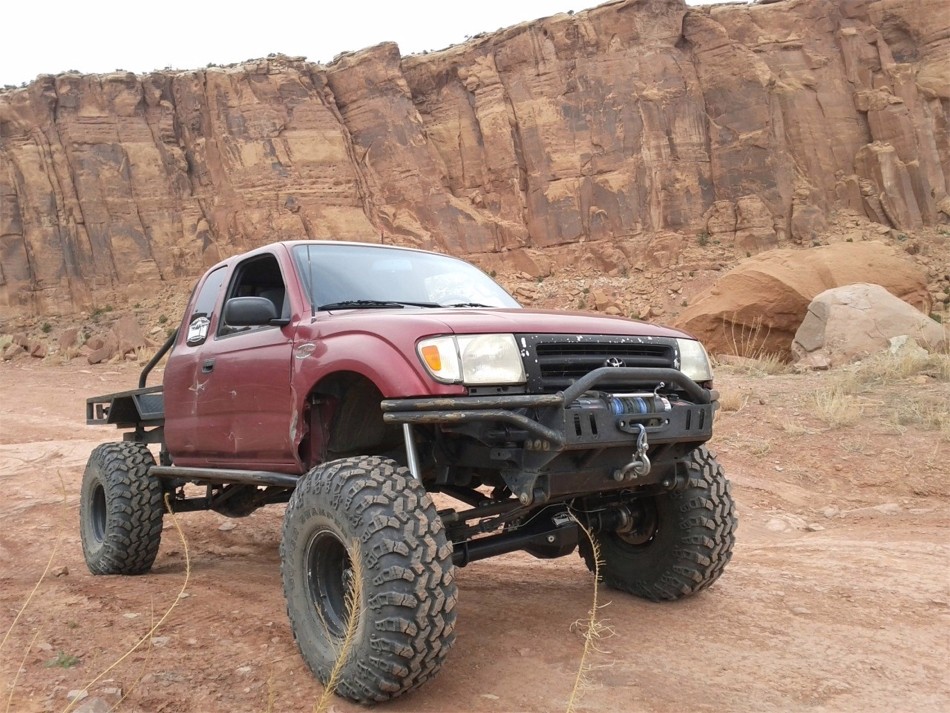
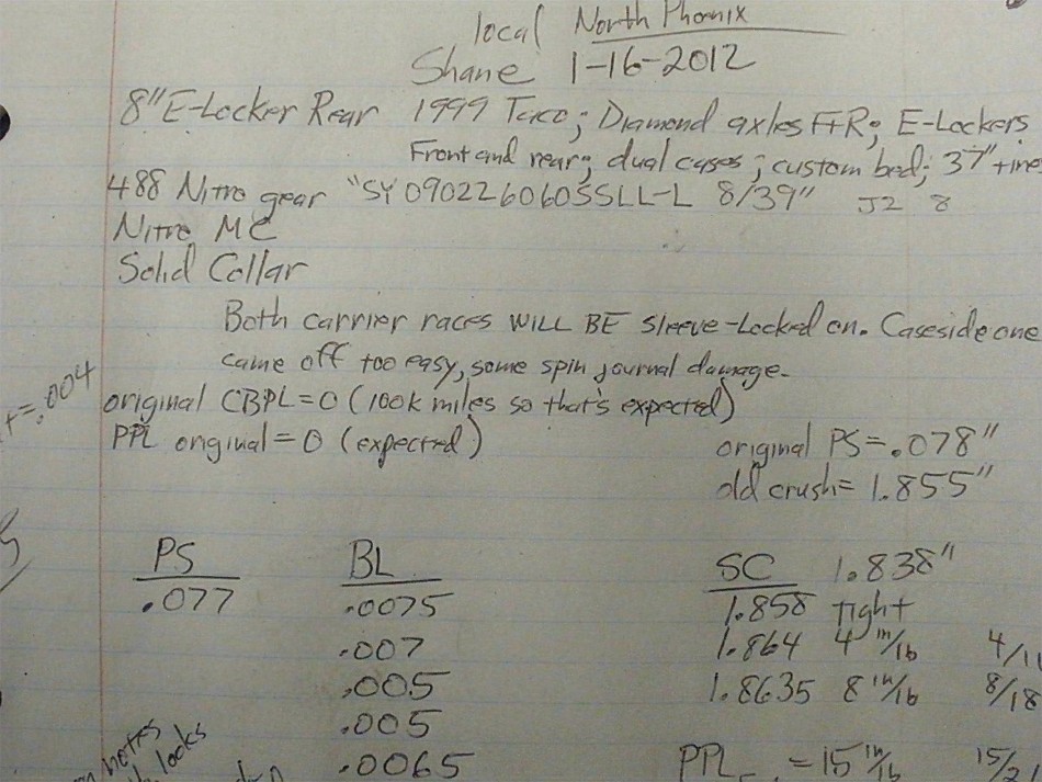
Moab 2011...Shane has a long list of mods. Major mods include Diamond axles front and rear ...E-lockers front and rear....Marlin dual cases...custom flatbed...37" tires. |
|
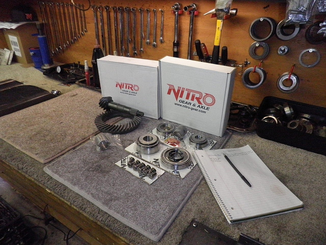
Shane had all the right stuff sent to me. One Nitro Gear 4.88 and Nitro master install kit and solid collar. The master kits from Nitro have genuine KOYO bearings. |
|
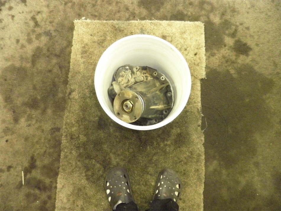
Shane is local to me so he drove over the busted e-locker over in a 5 gallon bucket. |
|
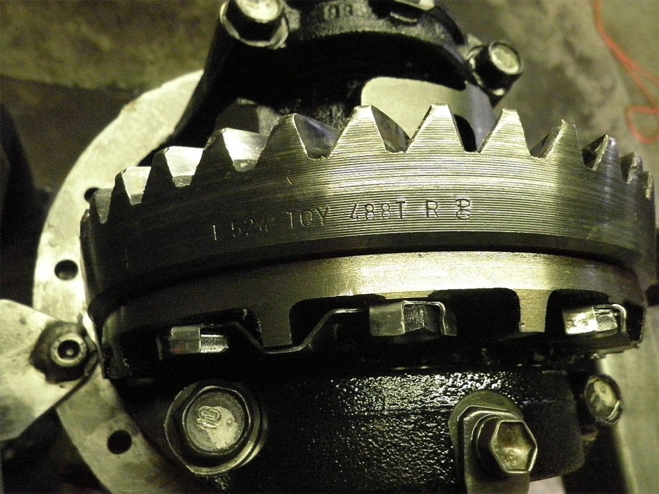
This install was done elsewhere locally here in the Phoenix area about 6 years ago. This is a Precision Gear brand ....excellent gear back in those days. Tom retired from that company....sold it to someone else. They changed gear manufacturers and I have noticed a difference in the gears. |
|
Shane uses his truck but uses it wisely. He doesn't get crazy on the gas trying to break a ring and pinion. |
|
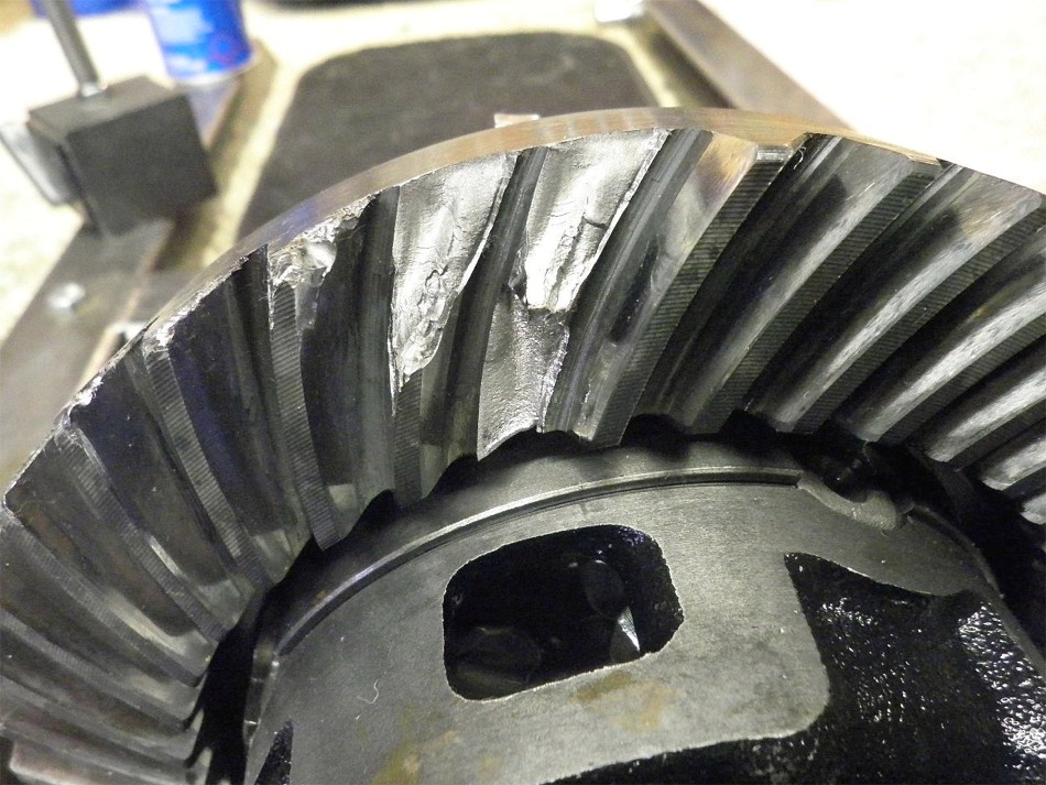
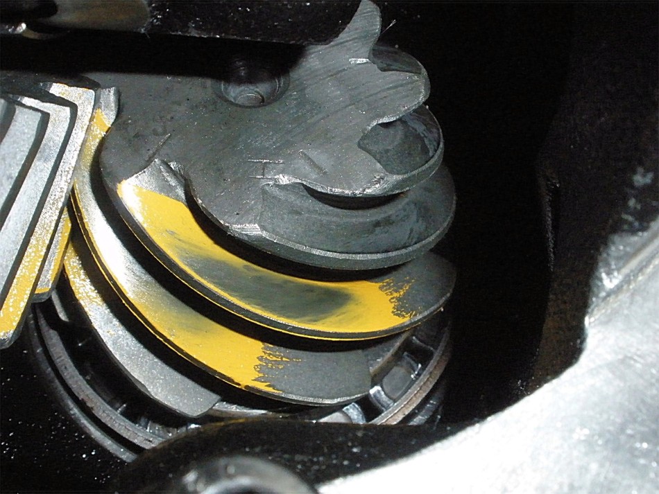
But 3 teeth finally did let loose after 6 years with large tires and dual cases. |
|
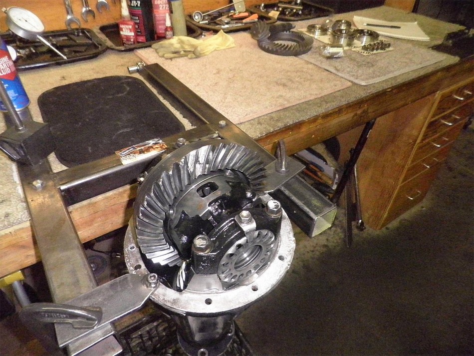
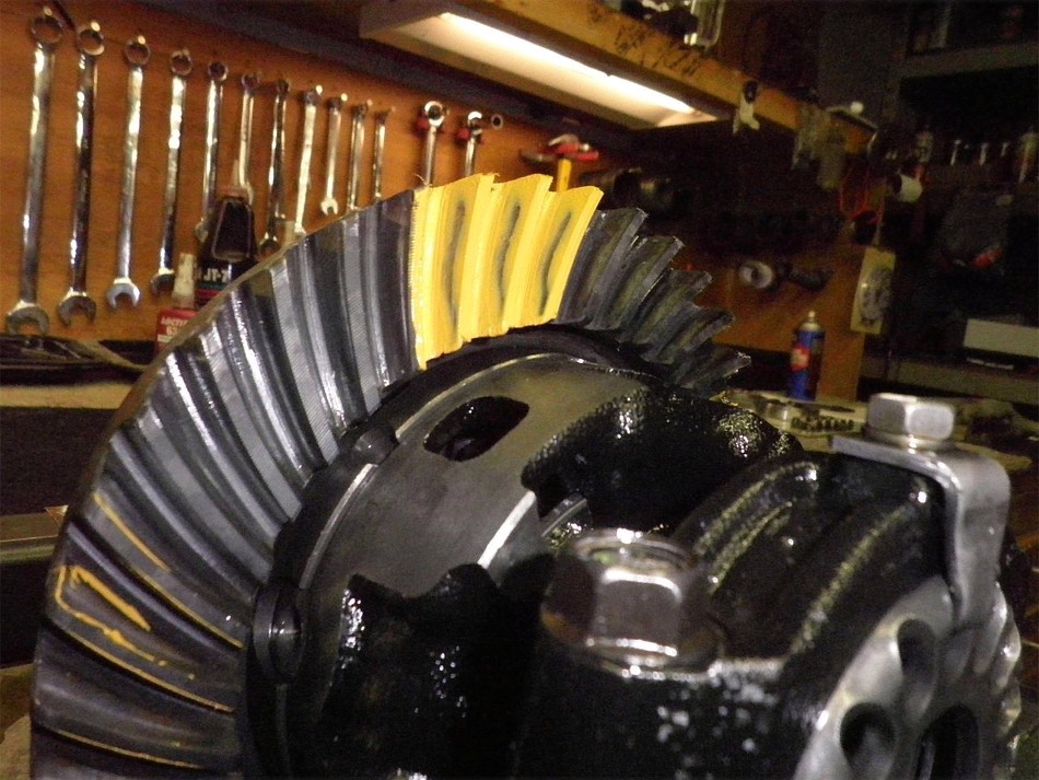
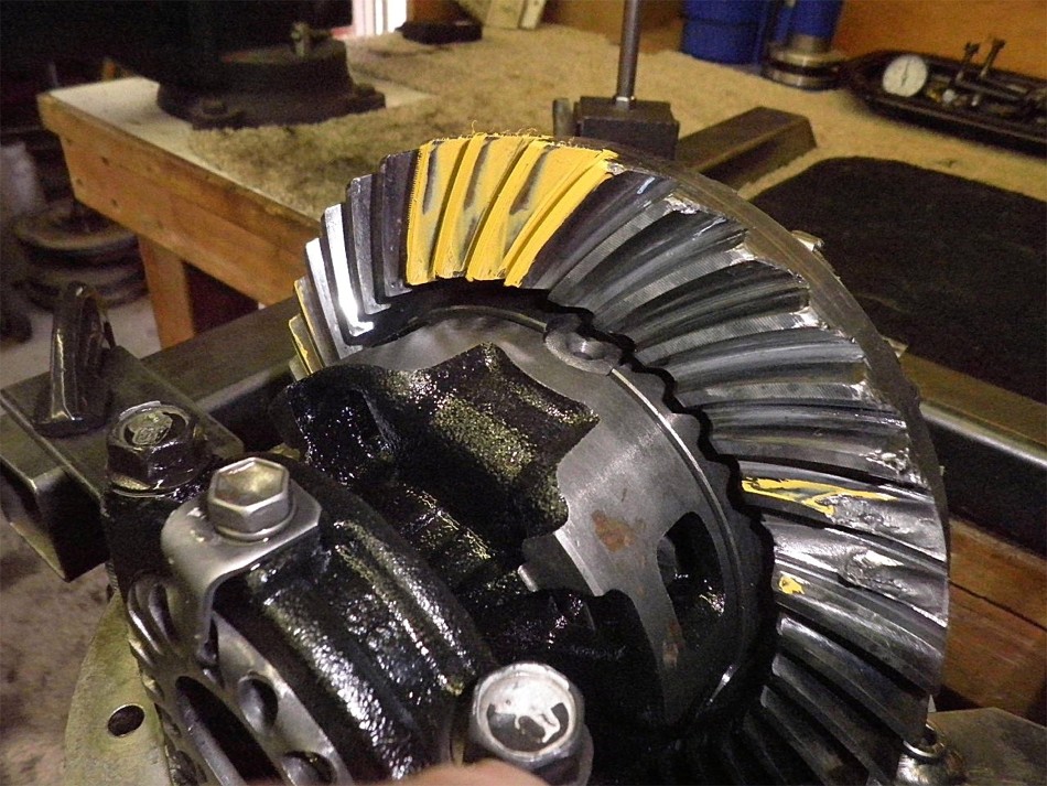
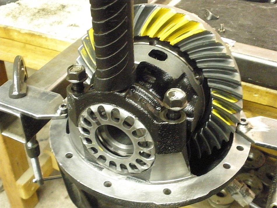
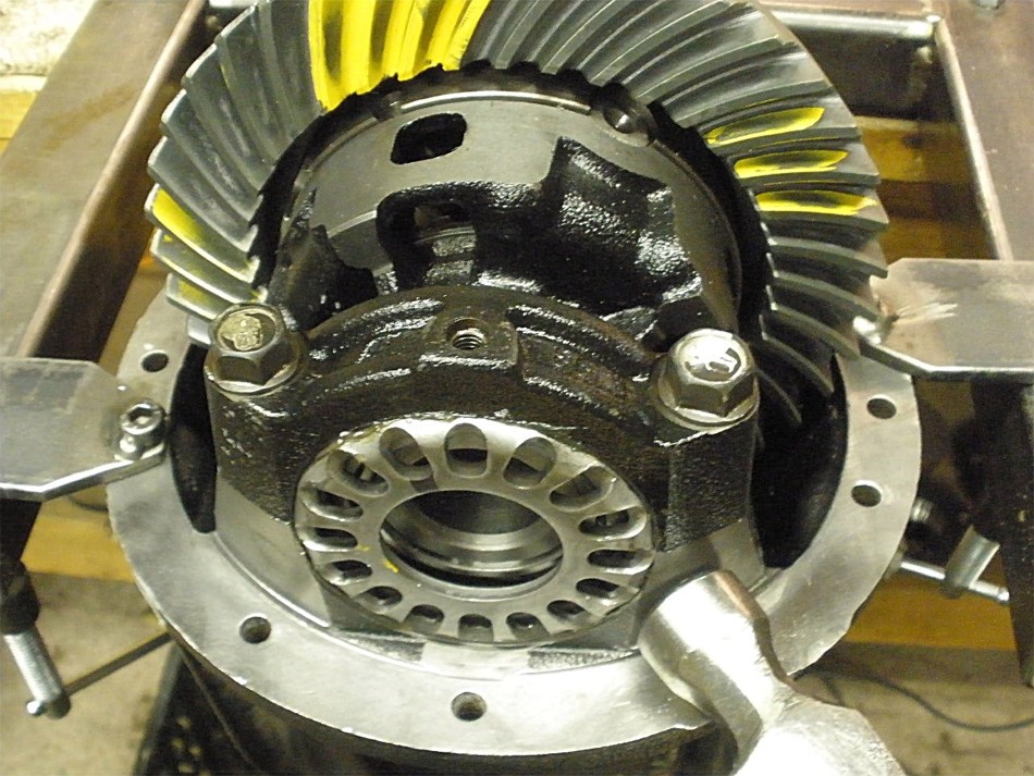
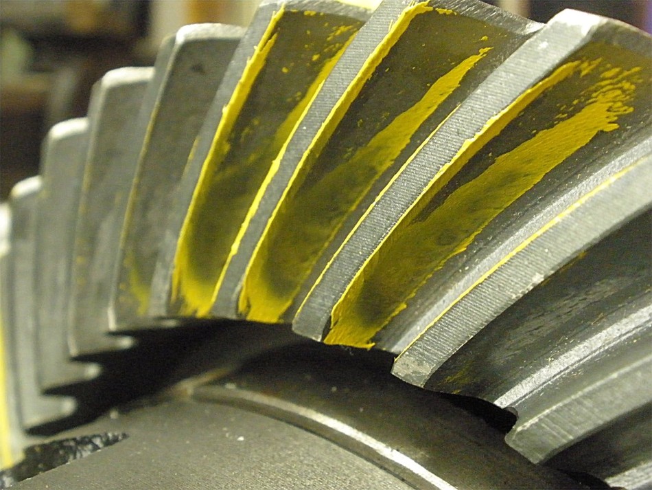
Before tearing it down, I took a quick paint check...drive side. The pattern actually appears slightly shallow. The fact that this lasted 6 years really does say something good about the old Precision gears. |
|
Coast side paint. |
|
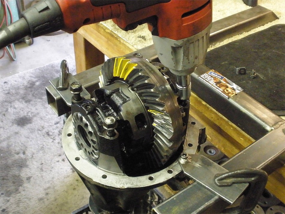
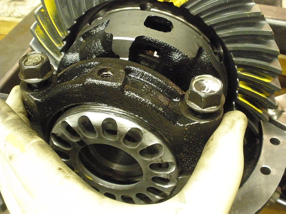
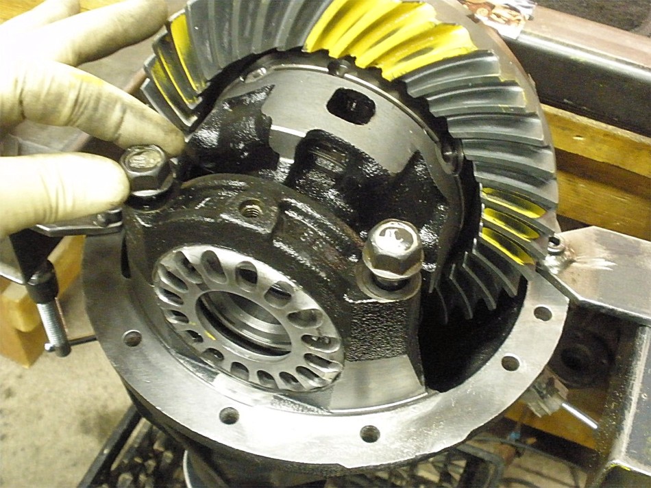
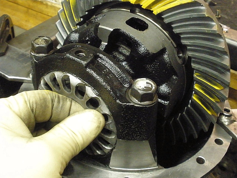
The teardown starts with the electric impact removing the four 17mm bearing cap bolts. |
|
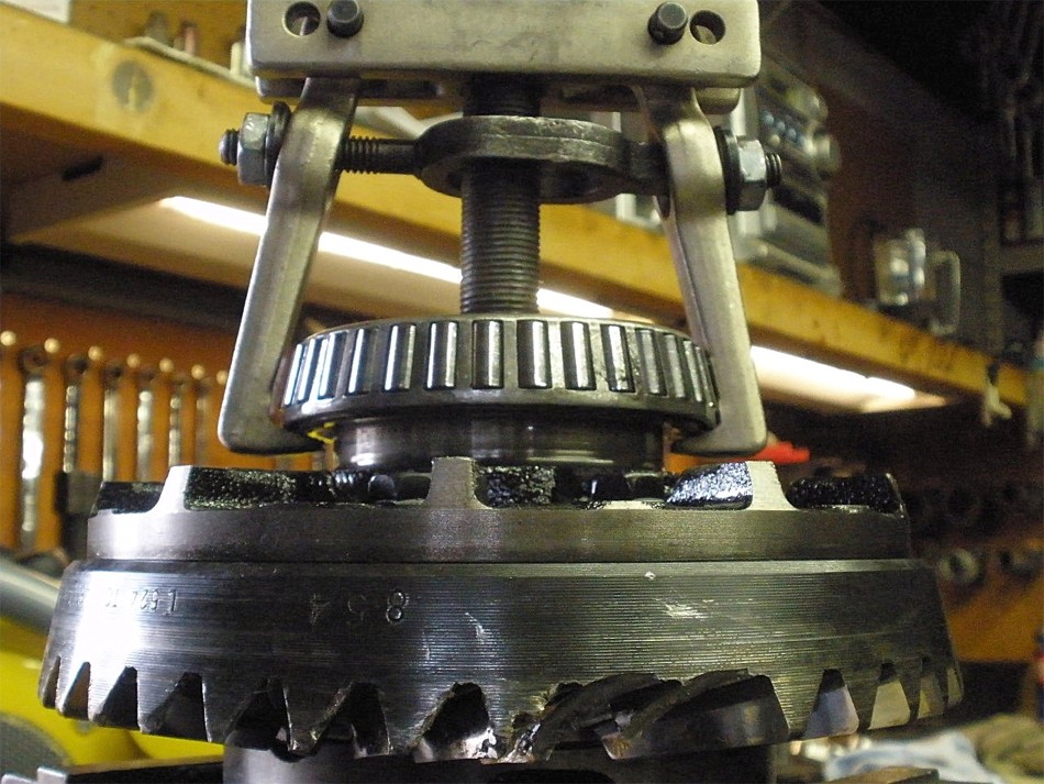
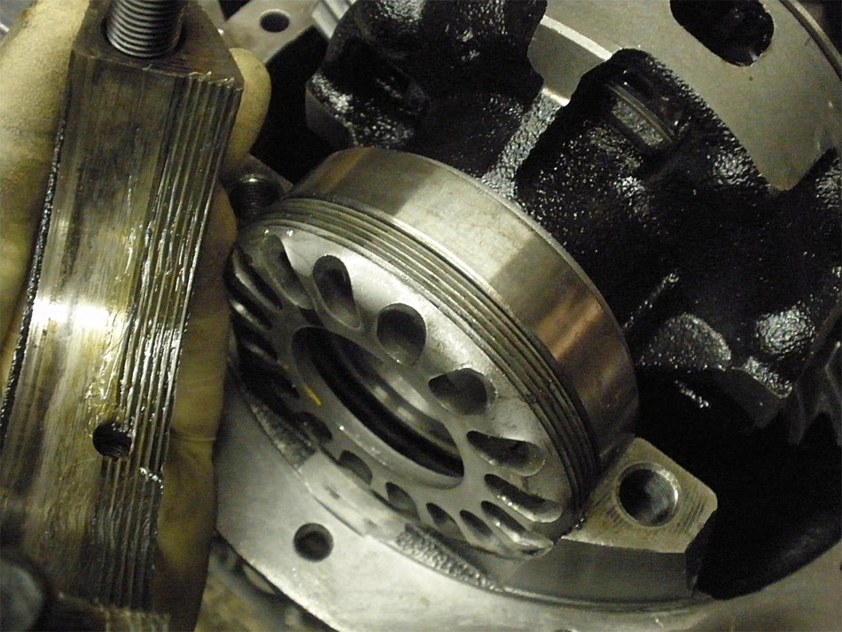
Old carrier bearings are pulled of with the right tool...OTC-4520 Differential Side Carrier Bearing Puller Kit |
|
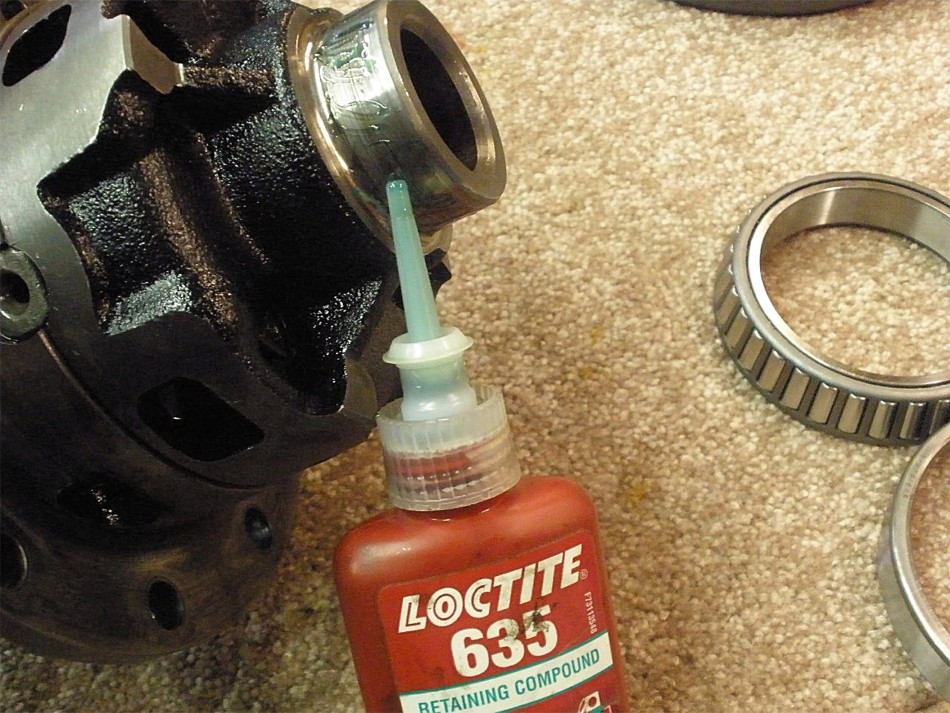
I did notice that one of the journals had some spun damage and the new bearing dropped on too easy. This is when retaining compound is used. I often lightly sand the surfaces with rough sandpaper and clean them thoroughly of all oils. I apply the compound to the journal surface and use a clean rubber glove finger to smear the green stuff evenly onto the entire surface. |
|
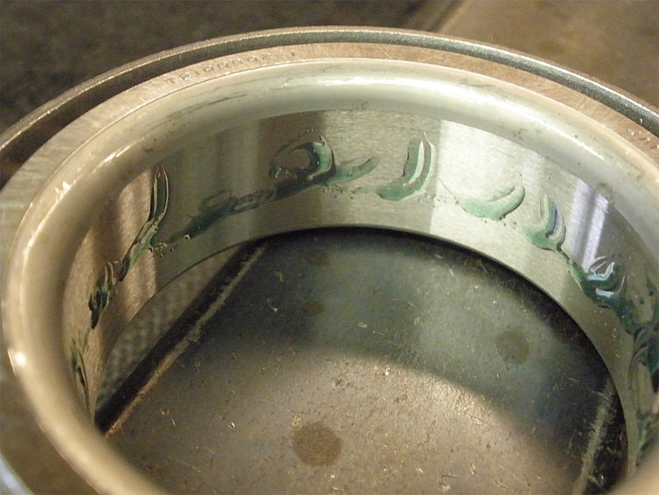
Same goes for the the inside of the bearing itself. I allow 24 to 48 hours for it to properly set up and continue with the install then. |
|
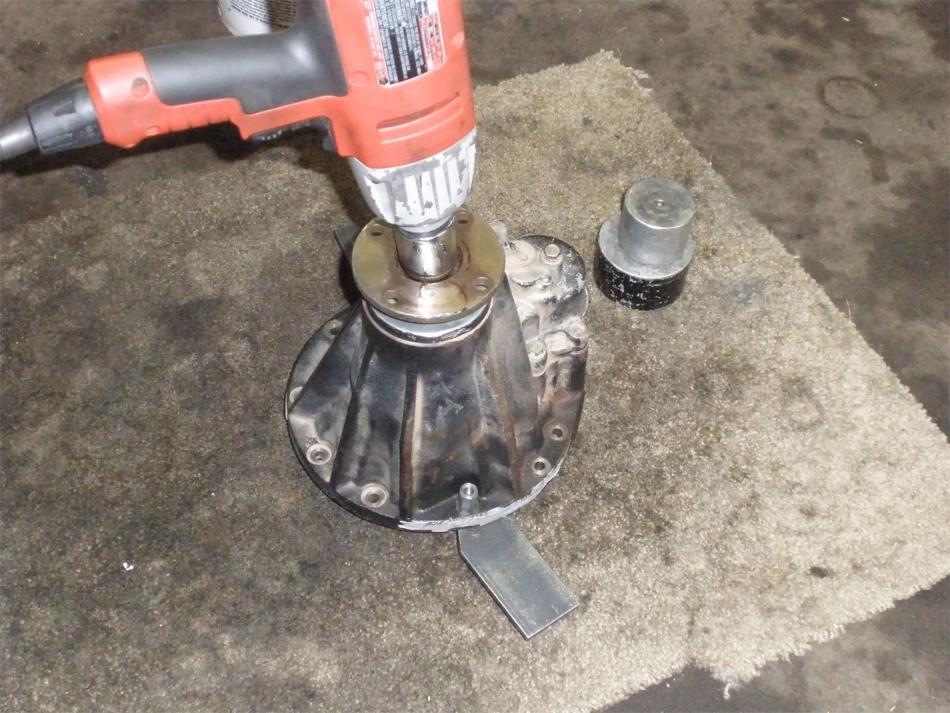
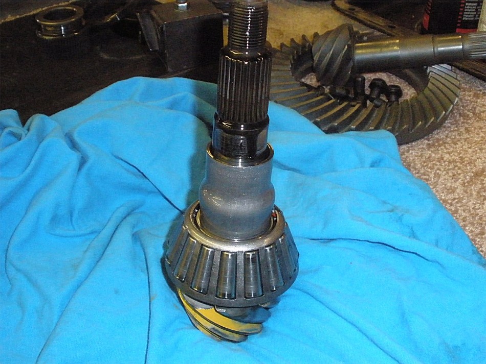
So, while that's setting up, I can do some work on the pinion end. The electric impact whizzes the 30mm nut off in less than 2 seconds. |
|
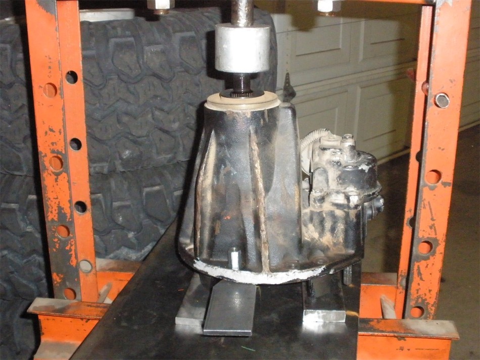
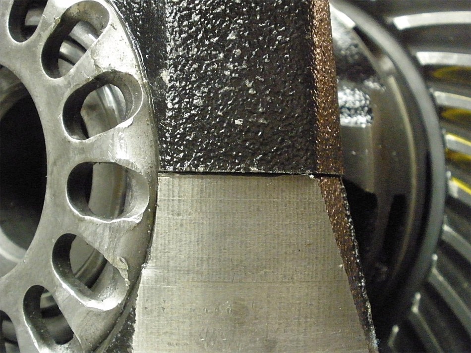
Most of the time with high mileage pinions, they just fall out when the pinion nut is spun off....not this one. Considerable pressure was required to press it out. |
|
Nothing unusual here. The crush sleeve served its function well for 6 years. |

|
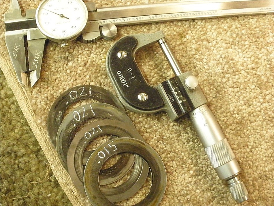
I'm pressing the inner pinion bearing off to inspect the shim. The cheap Harborfreight bearing separators just don't grab the bearing as cleanly as this more expensive one does. This one ran me about $110 as I recall. OTC-1130 Bearing Splitter - 1/2in-9in |
|
Looks like about .078" for the pinion depth shim which is in the general ballpark of what it should be.
|
|
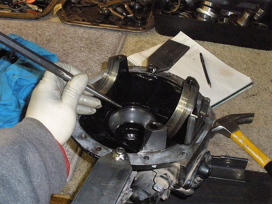
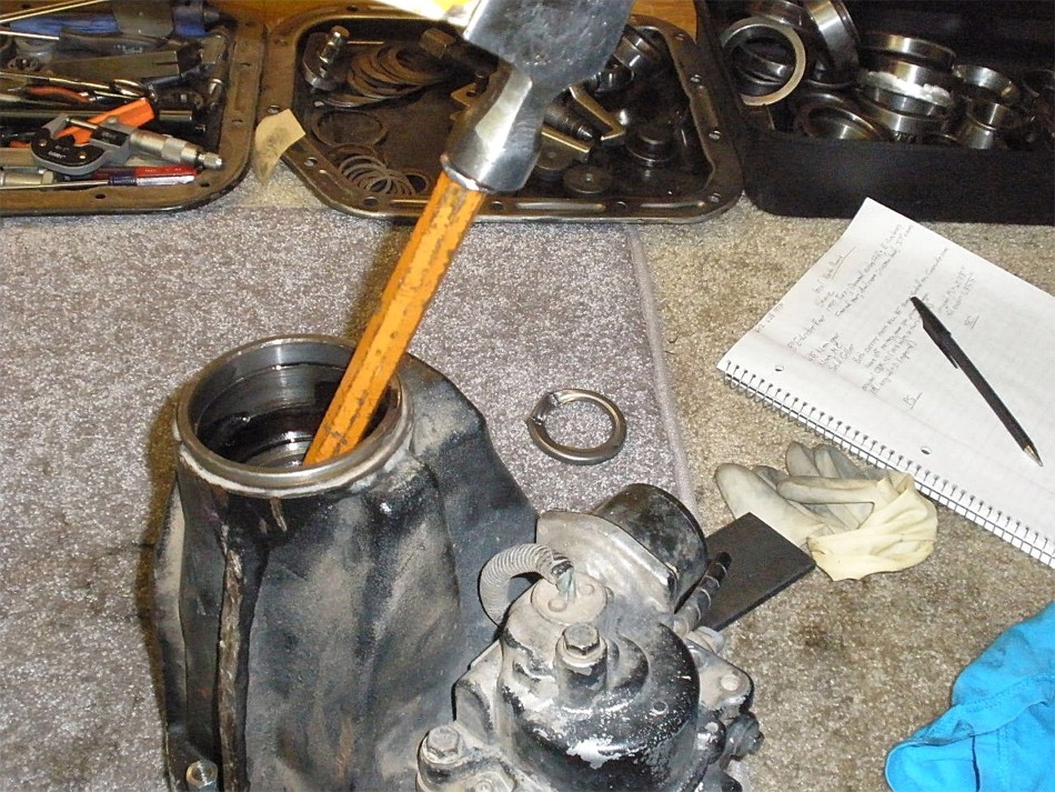
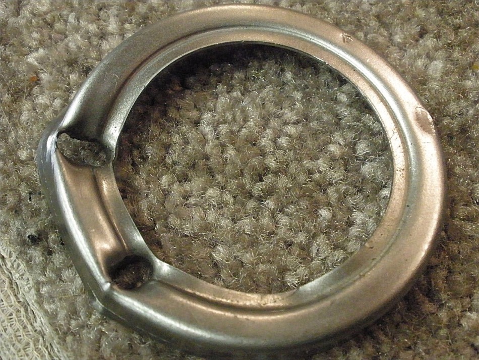
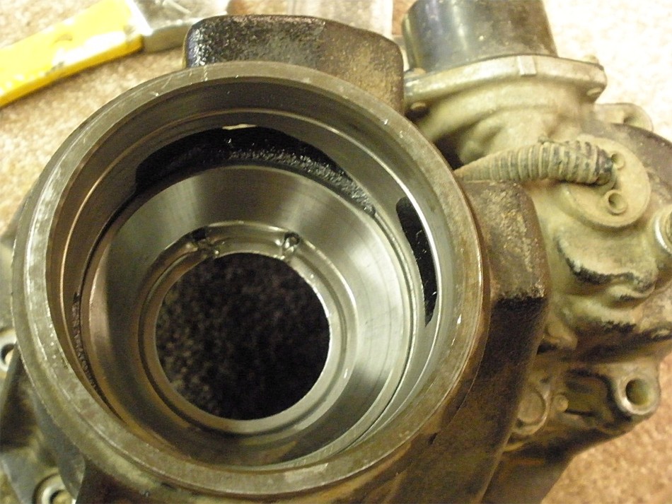
There's an oil retainer that gets in the way of punching out the small outer pinion race. But, if I do it right, I can punch a clean hole through the retainer and knock the race loose at the same time. This leaves 1 hole in the retainer that I can usually reform it closed again and re-use the retainer with no loss of function. |
|
The large inner race is easy to remove with a long chisel and hammer. |
|
I ended up punching 2 holes in the retainer and I know it doesn't look very good here but this is very savable. |
|
``` |
|
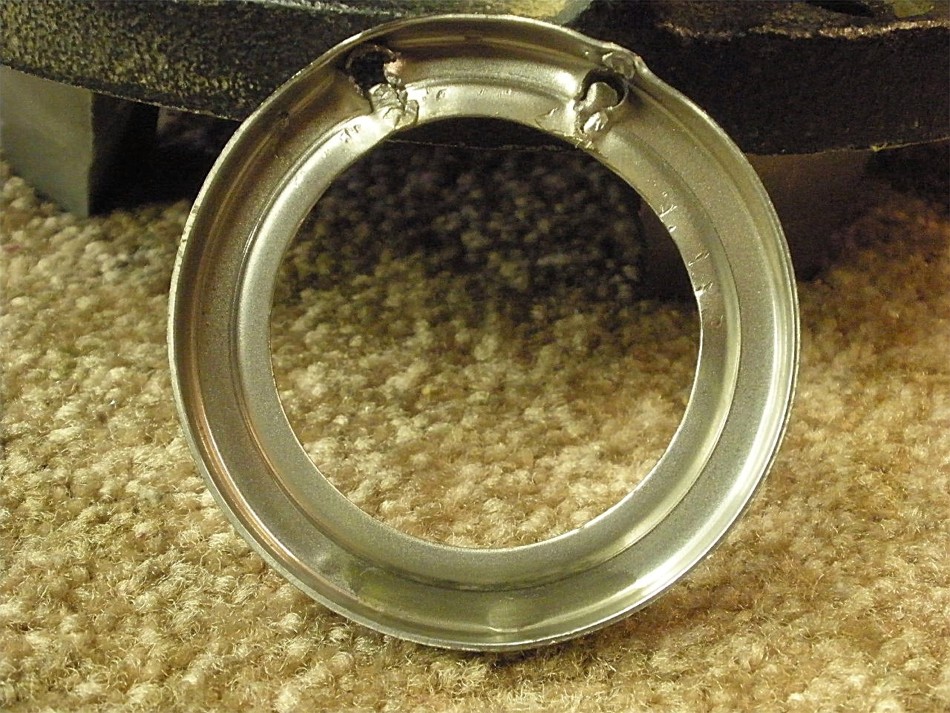
The retainer has the damaged area at the 12 oclock straight up position....oil is retained by the lower portion and not the upper end. |
|
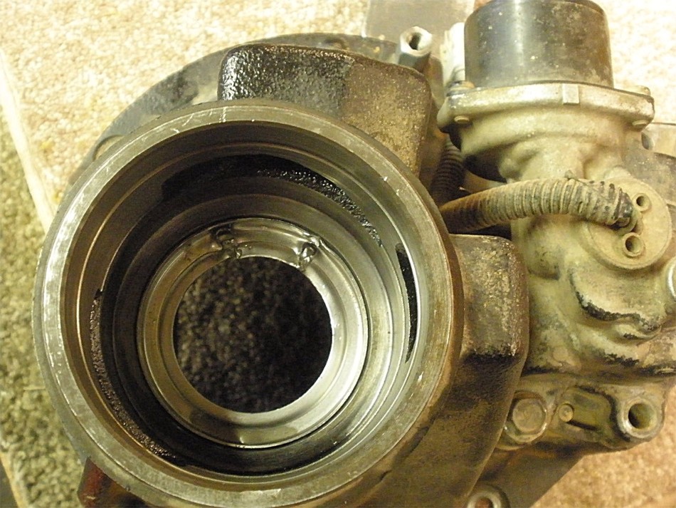
The outer race is tapped in place. |
|
``` |
|
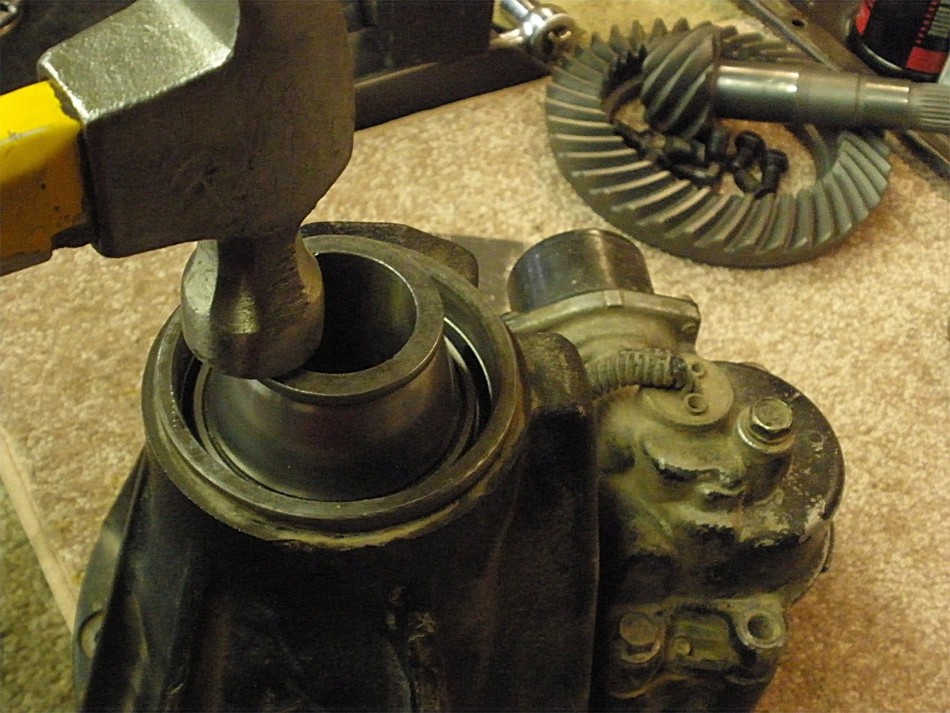
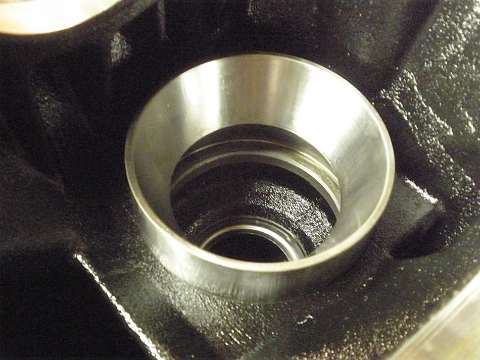
New race is placed centrally in the bore hole.... |
|
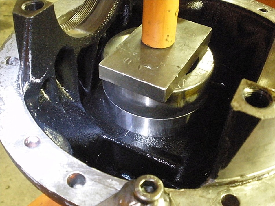
.....old race on top....if the race is level and started "evenly" all the way around....and pressure is applied close to the center... |
|
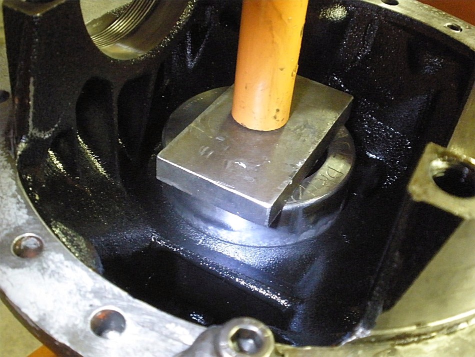
....then the race should recess into the hole until it bottoms out. |
|
A thick grease is smeared into the threads. |
|
The 2 bearing cap bolts are loosely threaded in place and the bearing cap is jiggled in place until it feels like the threads are in the right groove. |
|
A little "love tap" and the cap then fully seats itself.... |
|
...confirmed by the lack of any visual gap at all. |
|
Bolts are tightened finger tight and are snugged up firmly perhaps with a 17mm ratchet. |
|
If the threads are in mesh then the adjuster wheels will rotate easily. |
|
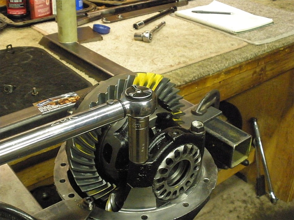
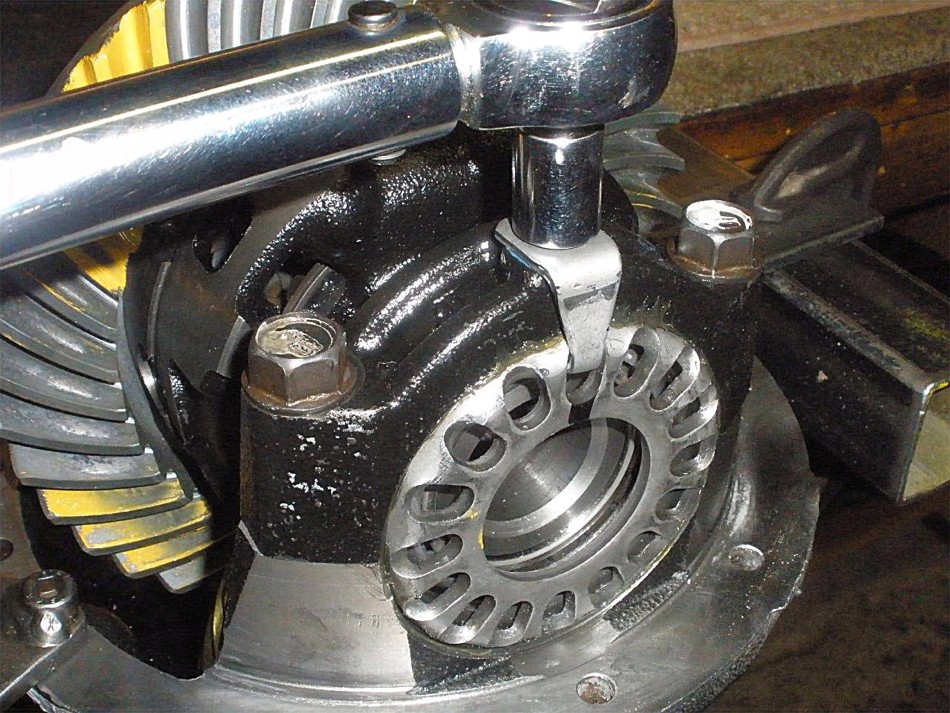
Now I can tighten the caps to full spec....75 ft/lb. |
|
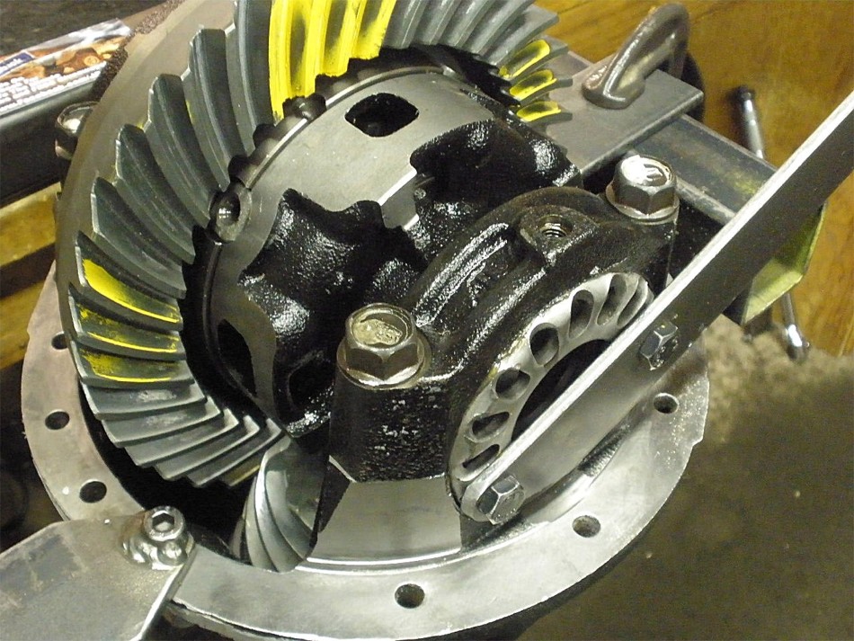
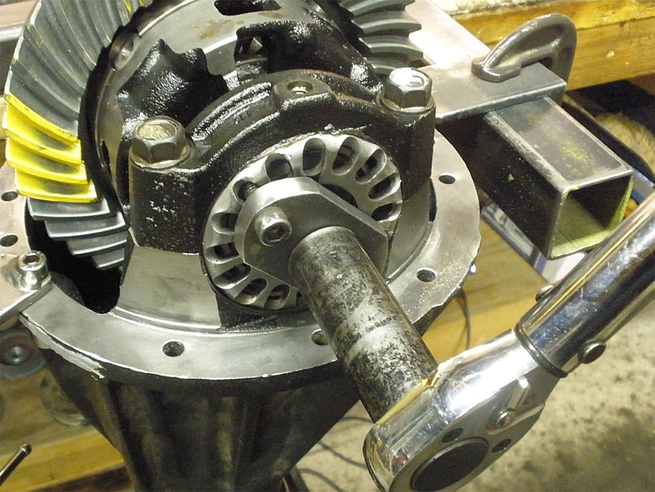
I use my simple yet highly effective homemade spanner tool to tighten both adjuster caps. It's an 18" long piece of 2" wide 3/16" thick steel flat stock. Plenty of available leverage to reach 150 ft/lb and greater if desired. |
|
I often rap all 4 corners (while rotating the pinion) to 'shock' the tapered rollers into equal tension with each other. |
|
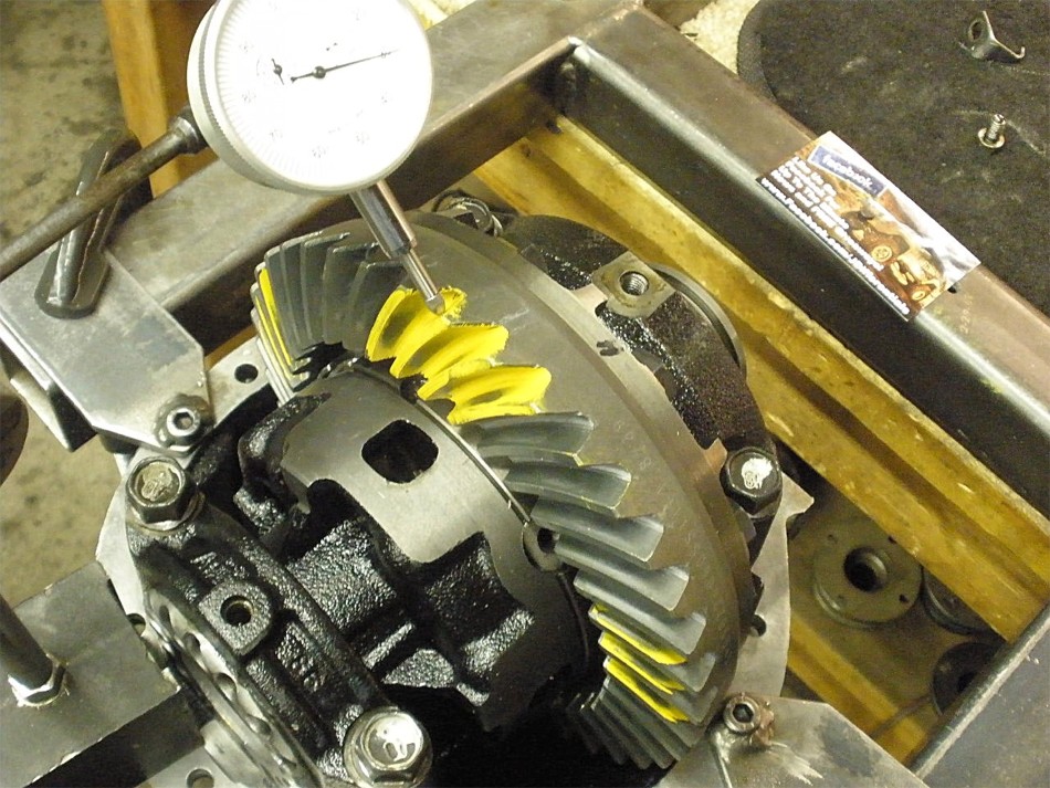
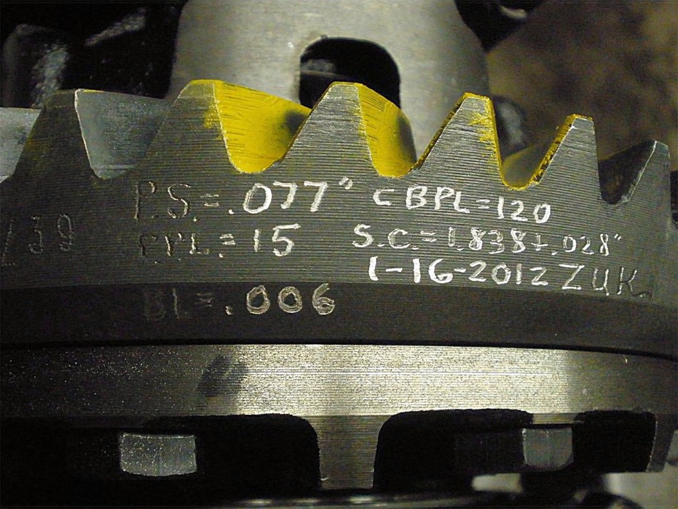
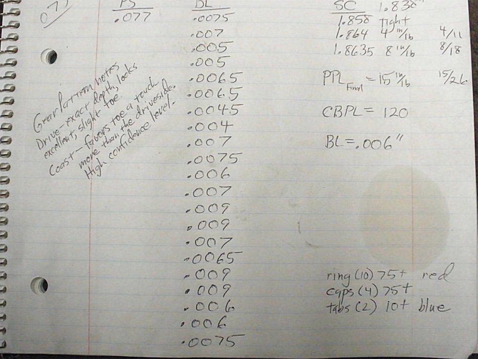
Backlash is fine tuned. For this particular ring and pinion, I saw lows of 005 and highs of 009. I checked every other tooth as shown in the notes at the end of this link. |
|
CBPL check....My torque wrench started to move the wheel when it was set to 120 ft/lb. |
|
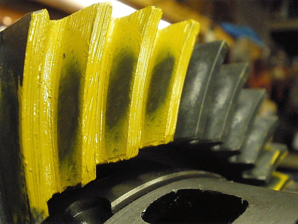
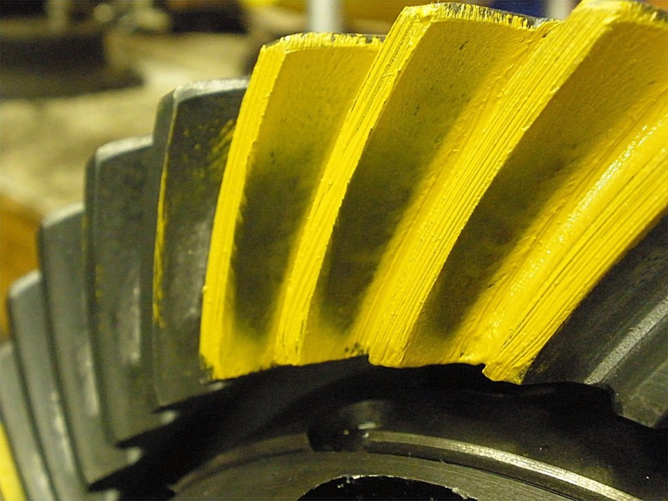
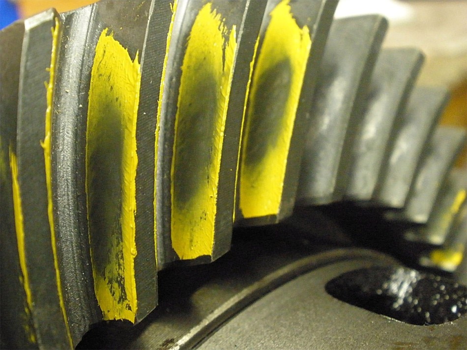
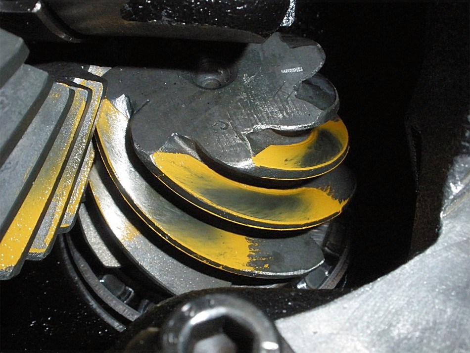
Now the pattern is checked one last time. New yellow paint is applied and a rag applies pressure to the pinion flange while the 17mm wrench rocks the ring gear back and forth about 3 times. This drive side is at exact depth and is centered from toe to heel(bottom to top in the pic). Shim is 077. |
|
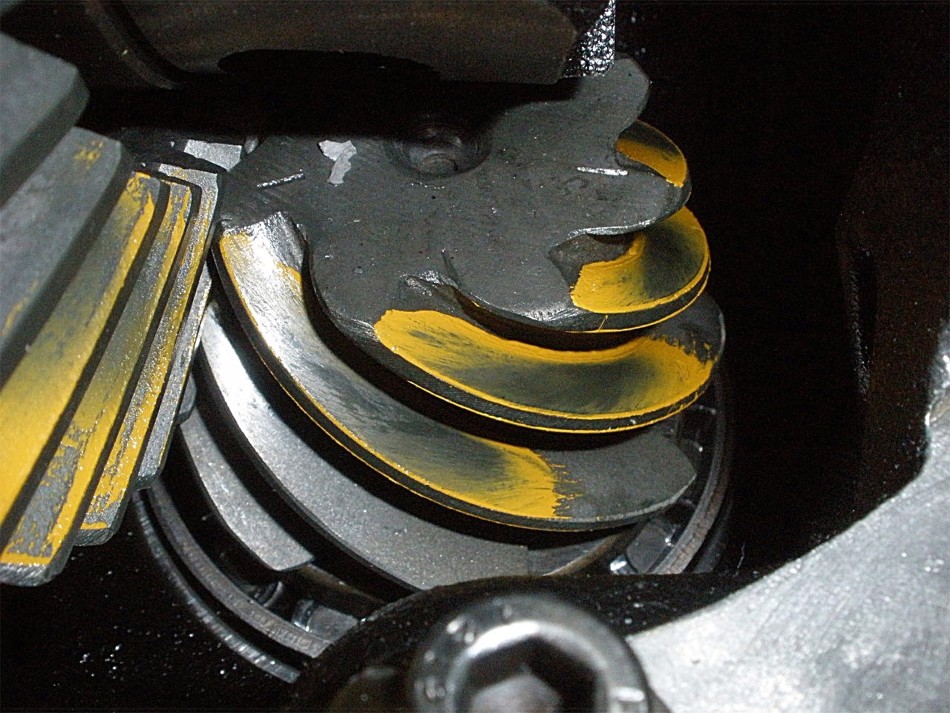
Coast 077...is actually favoring the toe end which is not the typical case but very much desired. |
|
The reverse painted teeth confirm correct depth. |
|
coast. |
|
The pinion driveside has a small tail on the right side...confirming correct depth. |
|
...another shot. |
|
...another. |
|
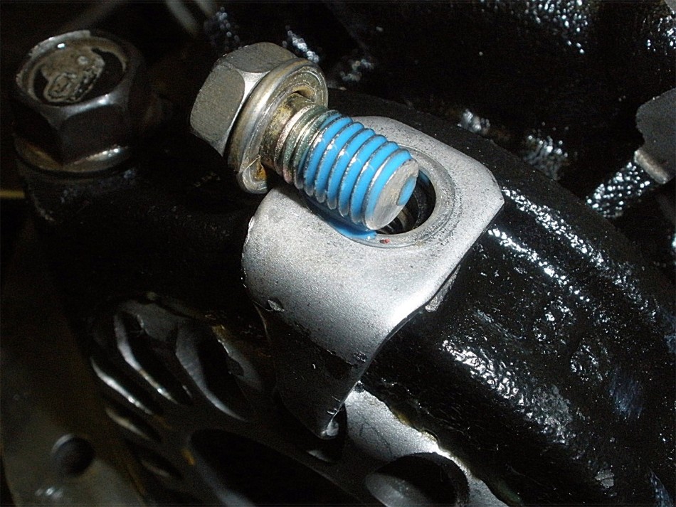
Blue medium strength Loctite is applied to the locktab bolts. |
|
10 ft/lb per factory spec. |
|
Specs measured are now scribed into the tough ring gear with a dremel tool with a diamond studded tip. |
|
``` |
|
``` |

|