|
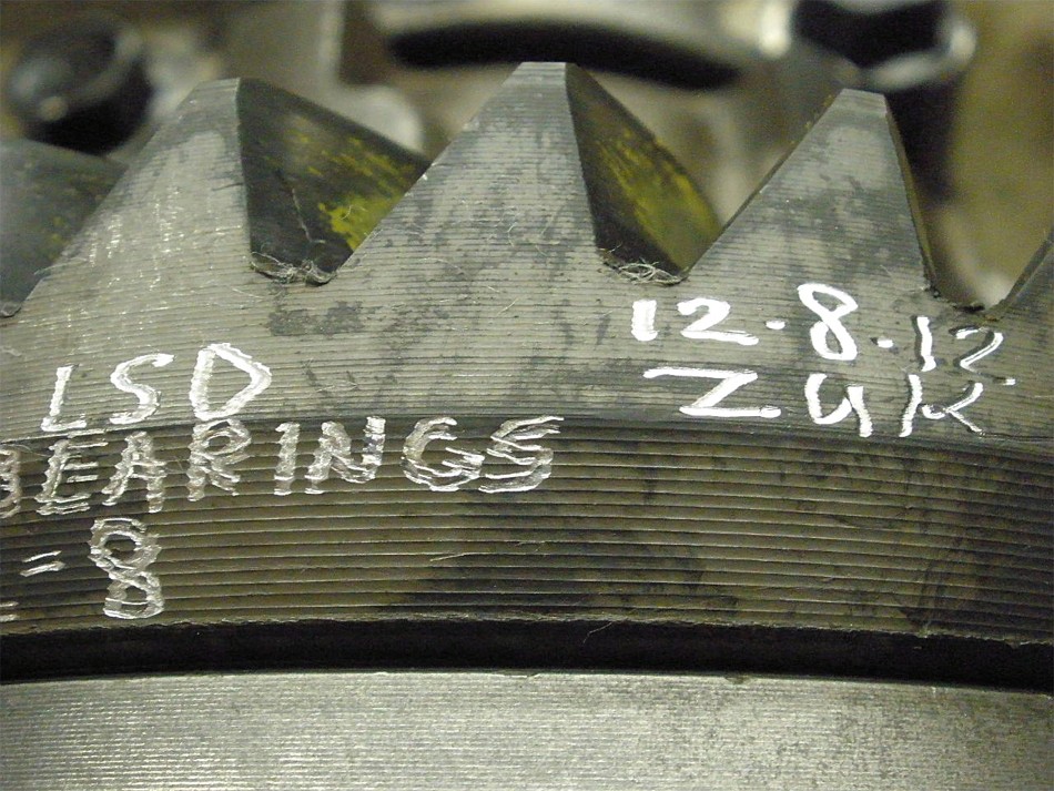
SUPRA LSD installed in a "4 cyl" 3rd using conversion bearings
|
|
(63 good size pics loading)
|
|
DEC 14 2012
|
|
|
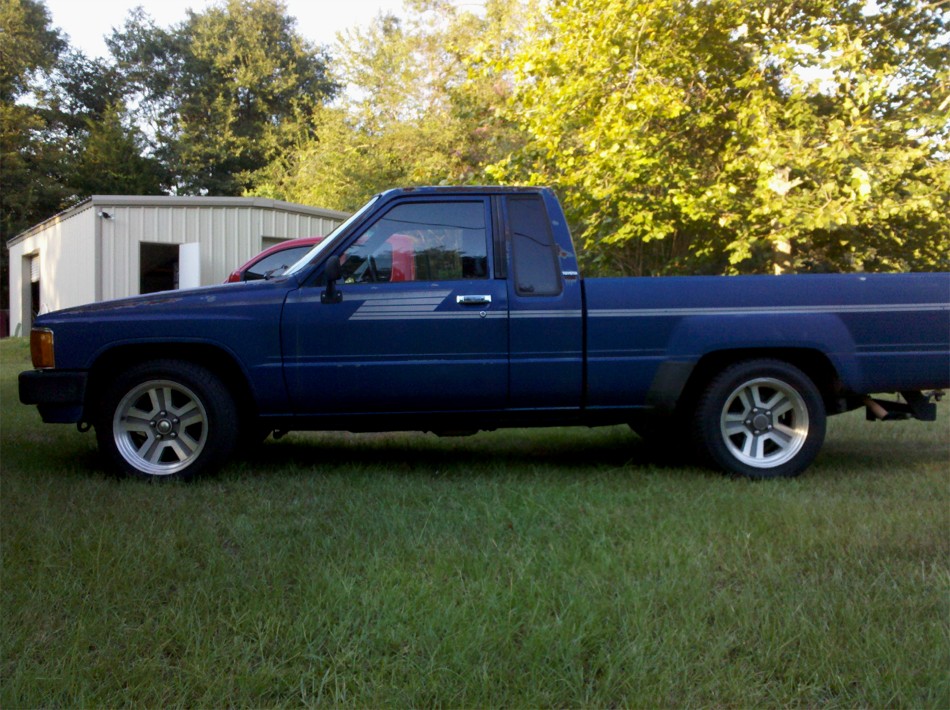
Daniel from Theodore, Alabama has a 2wd turbo Yota and was looking at
upgrading the traction at the rear 8" end.
|
|
|
|
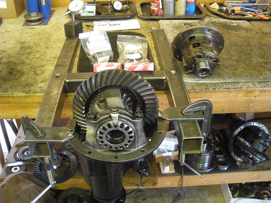
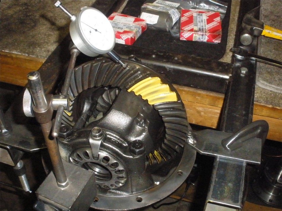
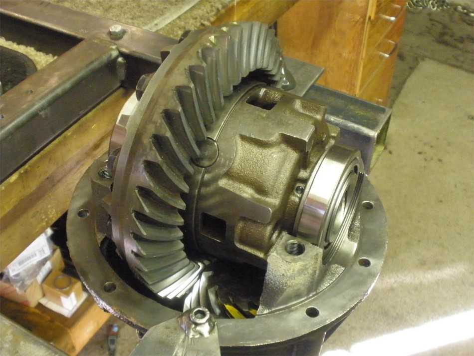
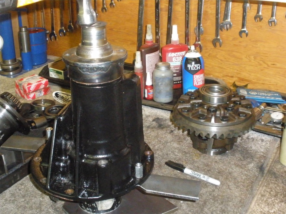
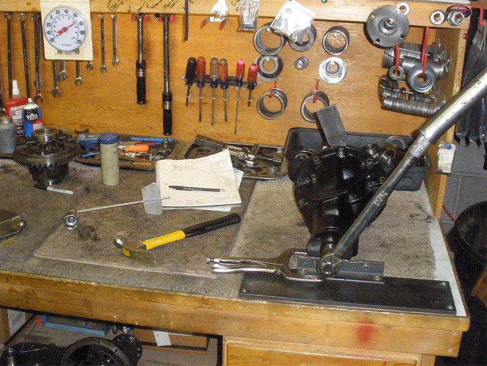
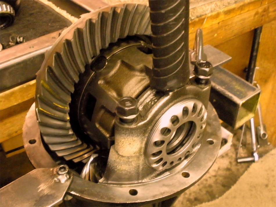
The 3rd is an 8" ring gear but as can be seen in my fixture it is also a
standard open case with 2 pinions. The V6 looking case in the background is
the Supra LSD that was rebuilt by weirperformance.com.
|
|
|
|
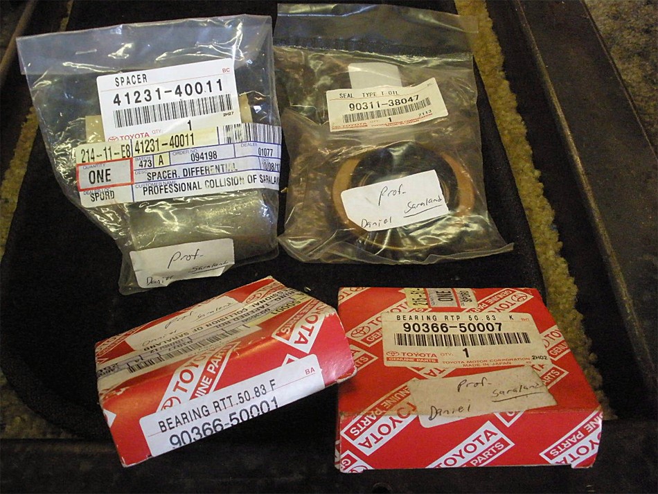
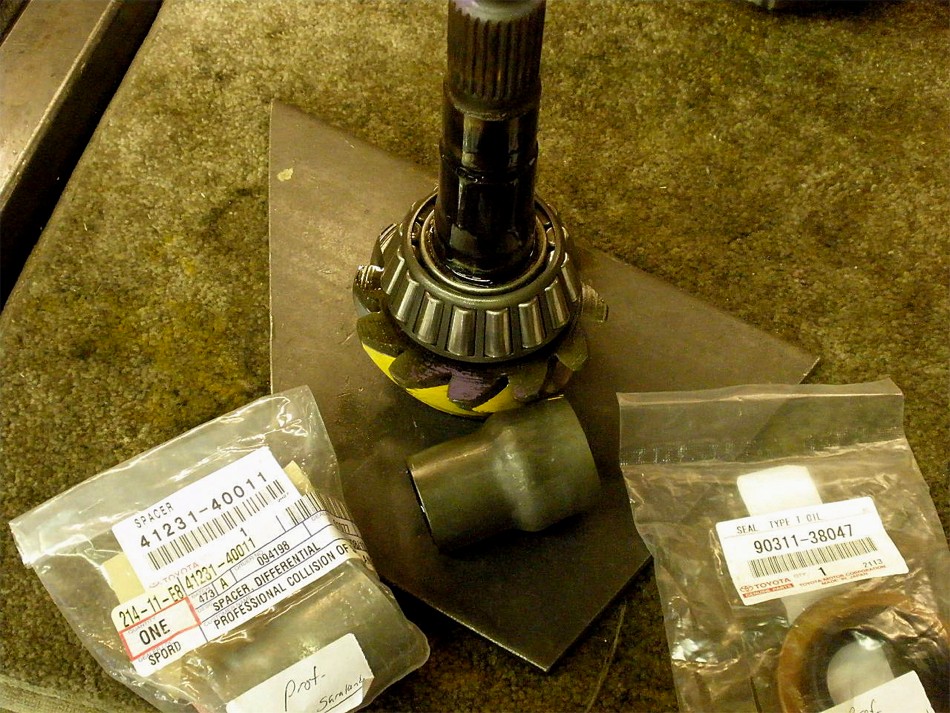
Daniel also included the components that were thought to be needed...upper
left is the factory V6 crush sleeve....on the right is the usual pinion
seal....lower left is the factory Supra fat carrier bearing and to its right
is the skinny V6 truck bearing. The 2 V6 bearings will fit on the Supra but
they will not fit in the 4 cyl 3rd.
|
|
|
|
|
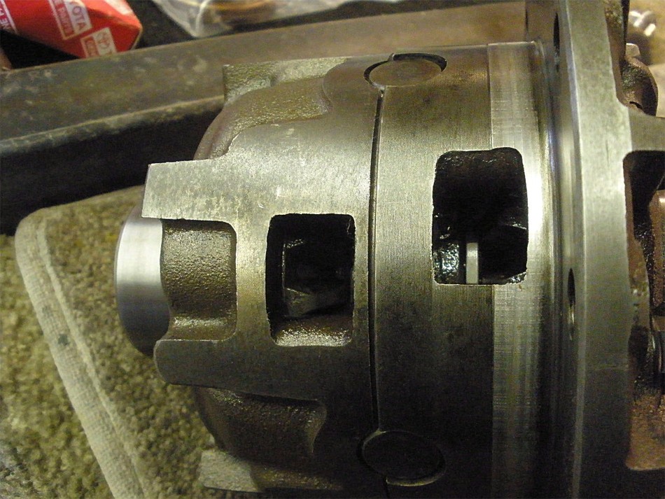
Sideshot of the Supra LSD.
|
|
|
|
|
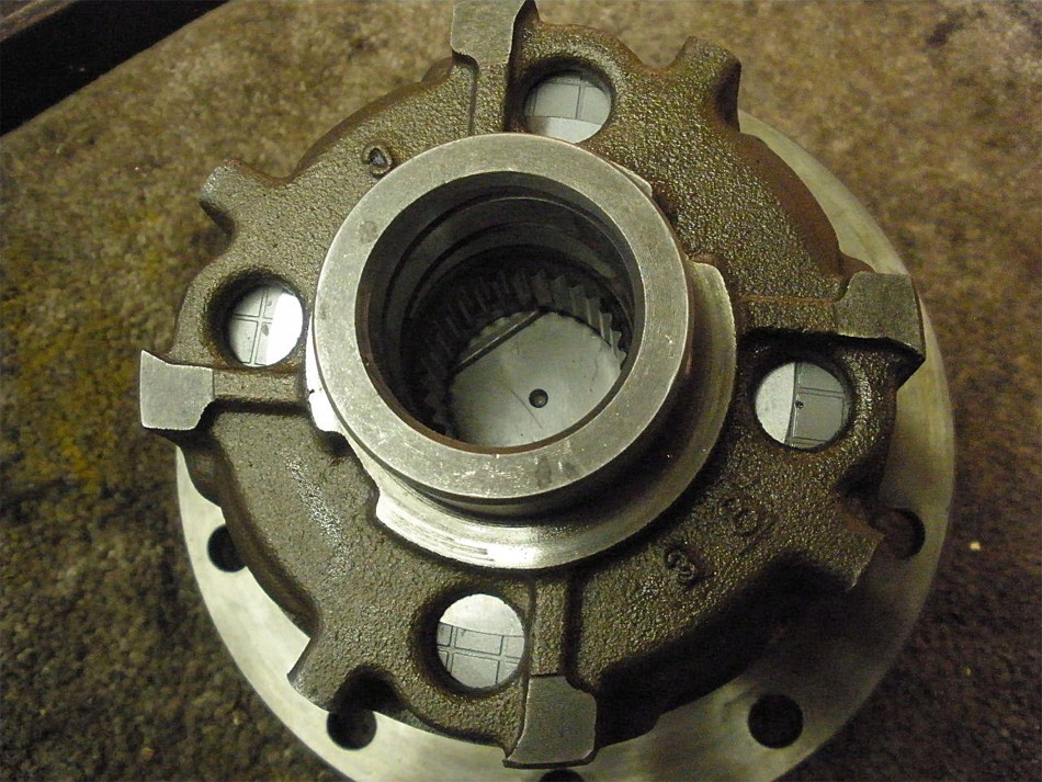
Endshot of the rebuilt LSD...
|
|
|
|
|
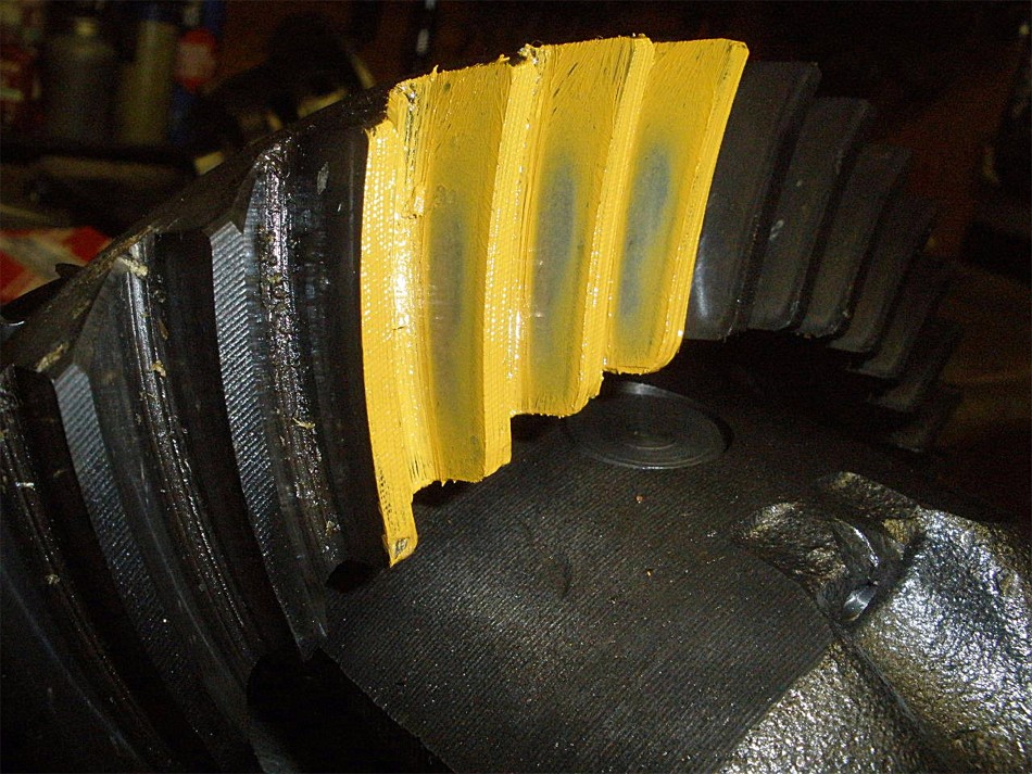
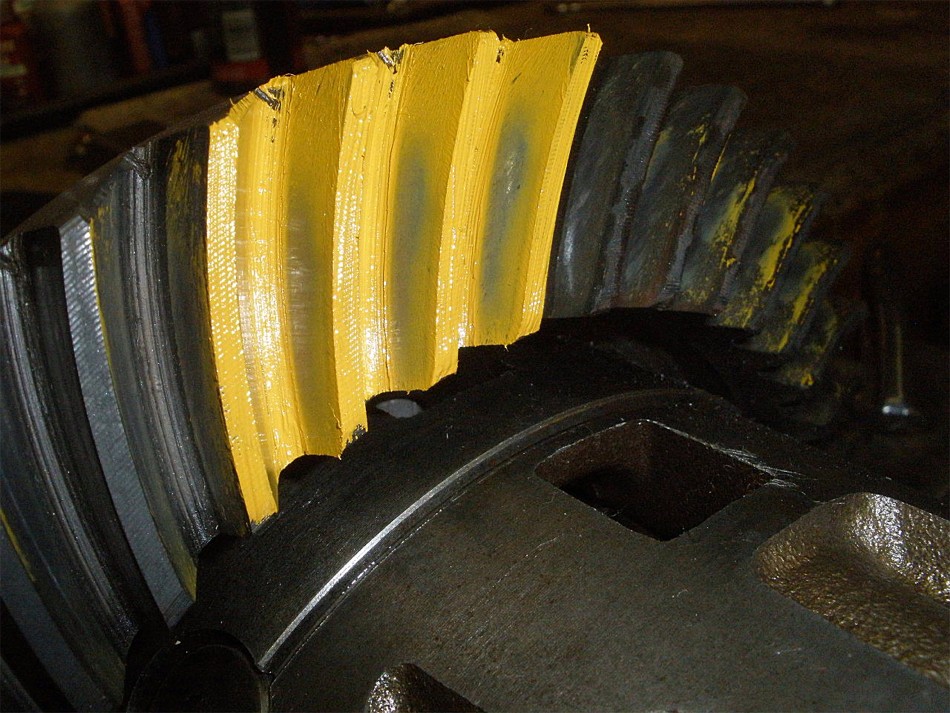
A preliminary paint of the drive side pattern...looks good.
|
|
|
|
|
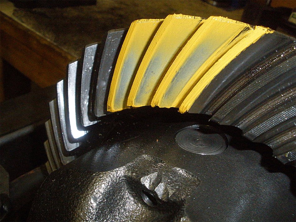
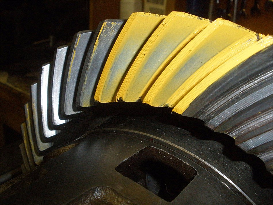
Coast side is aok also.
|
|
|
|
|
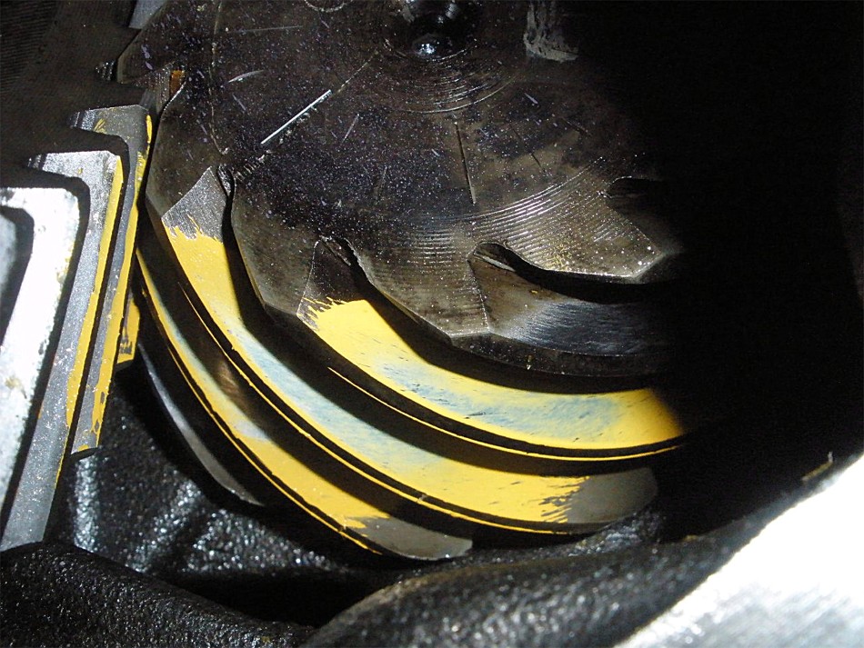
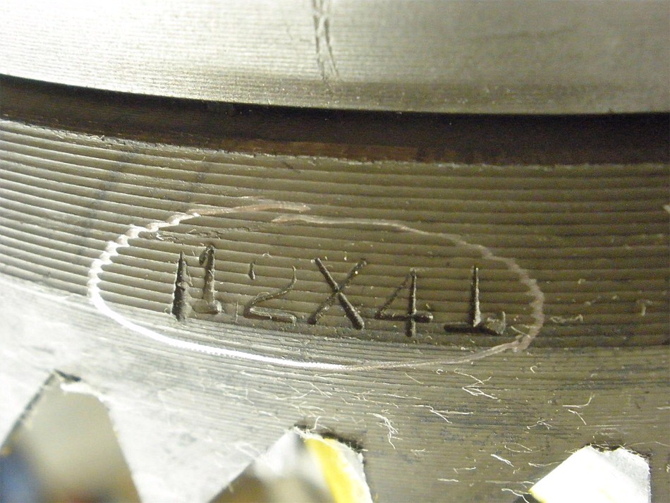
A shot of the drive on the pinion tooth.
|
|
|
|
|
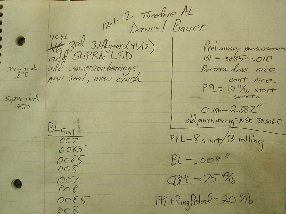
I also needed a target backlash reading....I was measuring about .0085" to .010".
|
|
|
|
|
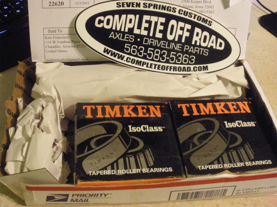
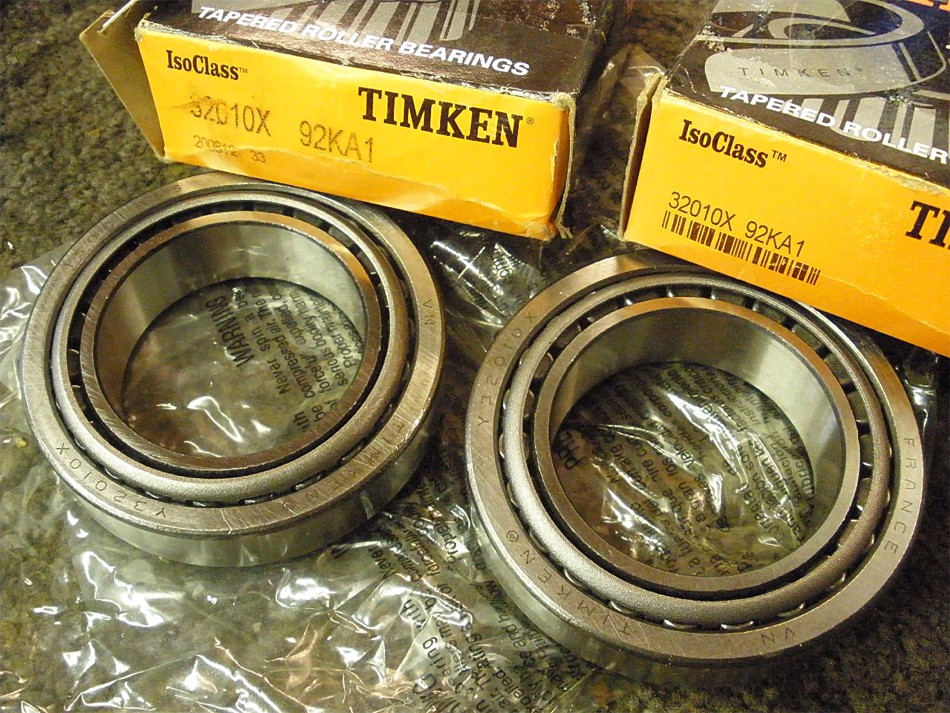
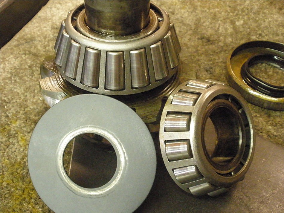
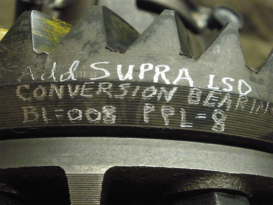
I ordered these "conversion bearings" from completeoffroad.com.
|
|
|
|
These bearings have the larger 50mm INSIDE diameter to press on the V6 Supra
LSD case and the smaller OUTSIDE diameter to fit in a 4 cylinder 3rd.
|
|
|
|
|
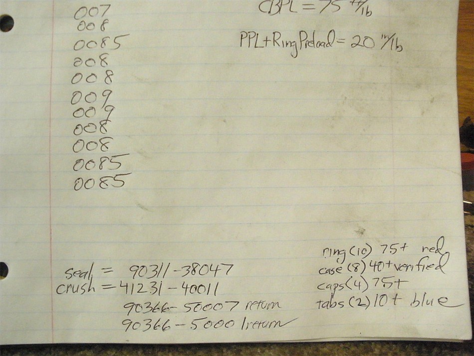
The ring gear was transferred over to the LSD...red loctite....
|
|
|
|
|
...and 75 ft/lbs.
|
|
|
|
The 8 long bolts that hold the case halves together were verified to be 45
ft/lb and they were all good.
|
|
|
|
|
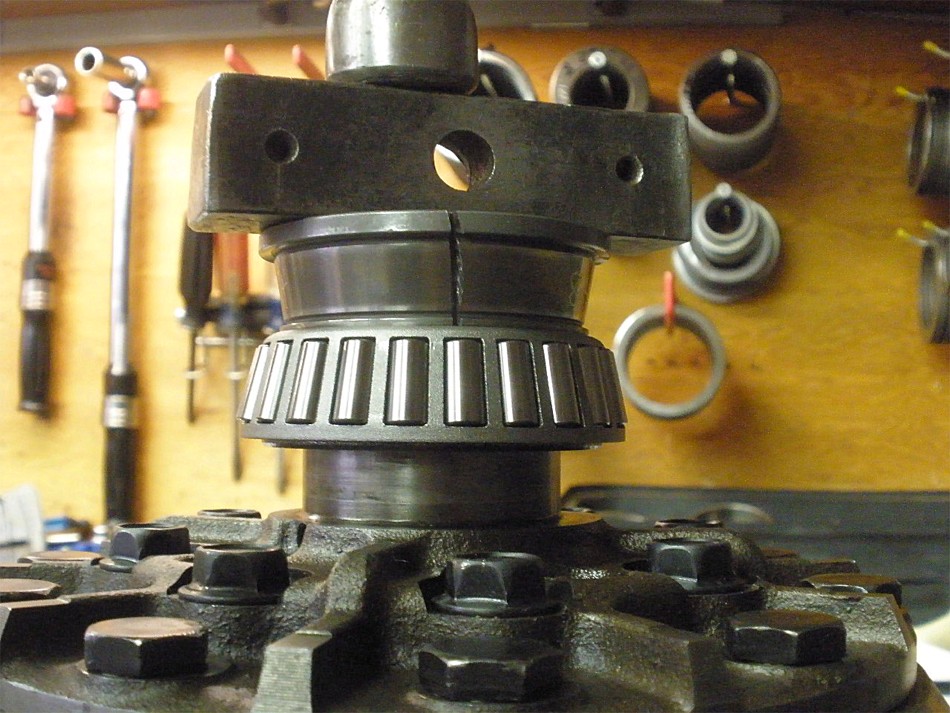
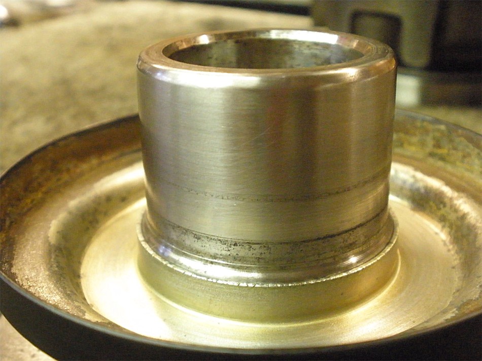
Conversion bearings are started with the right "interface hardware".
|
|
|
|
|
The press finishes the job.
|
|
|
|
|
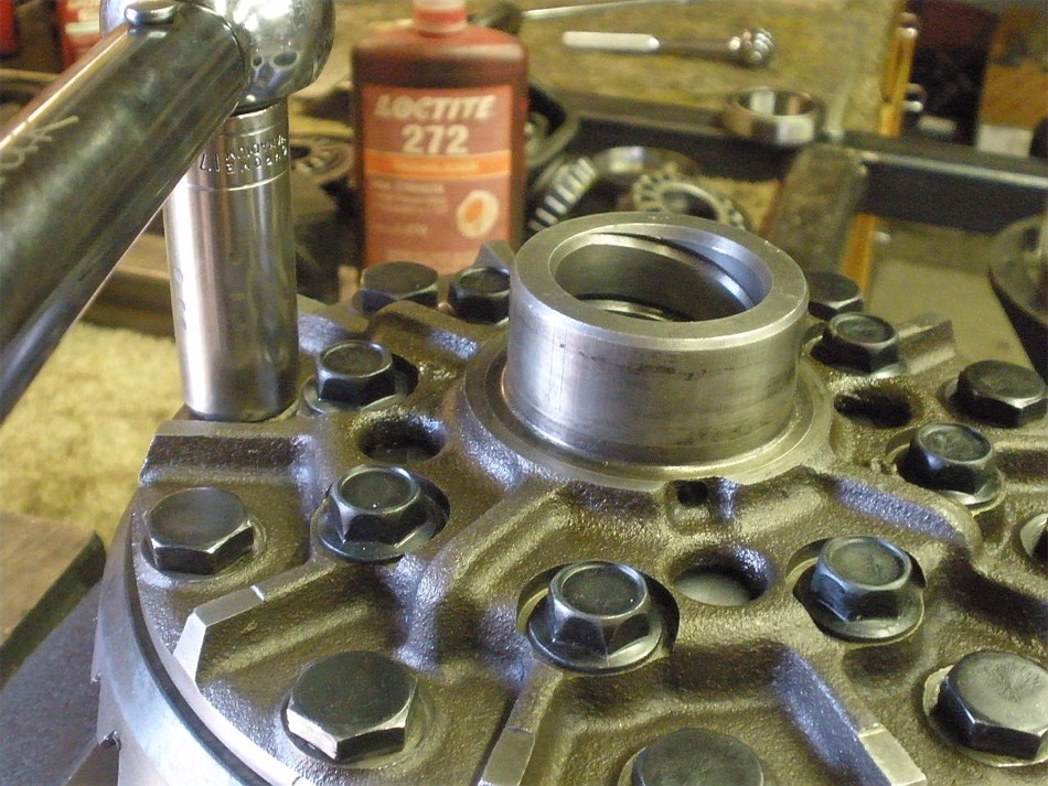
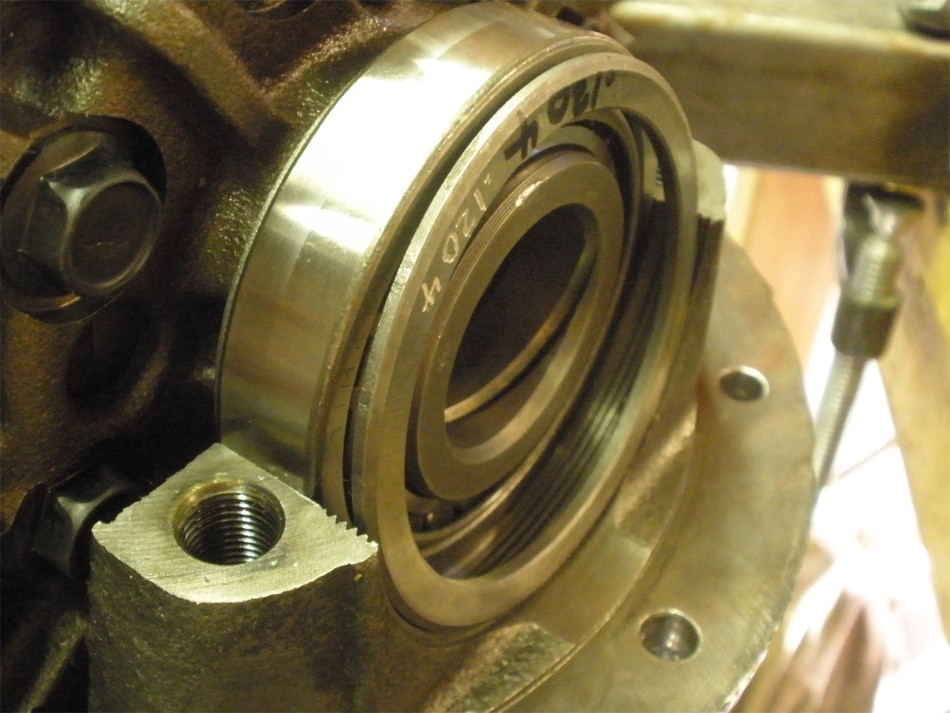
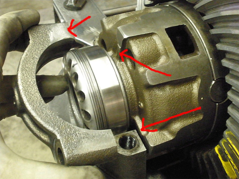
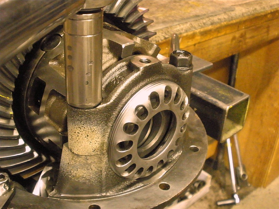
The LSD case is temporarily put in place to check the clearances.
|
|
|
|
|
I have washer plates (shims) that will take up the gap on this side.
|
|
|
|
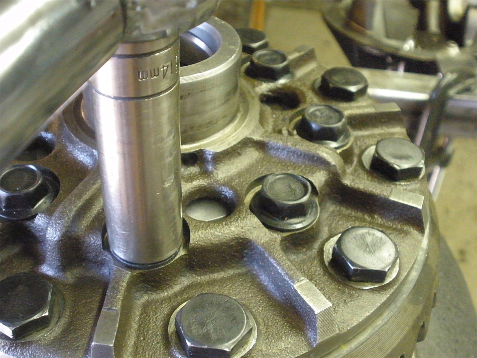
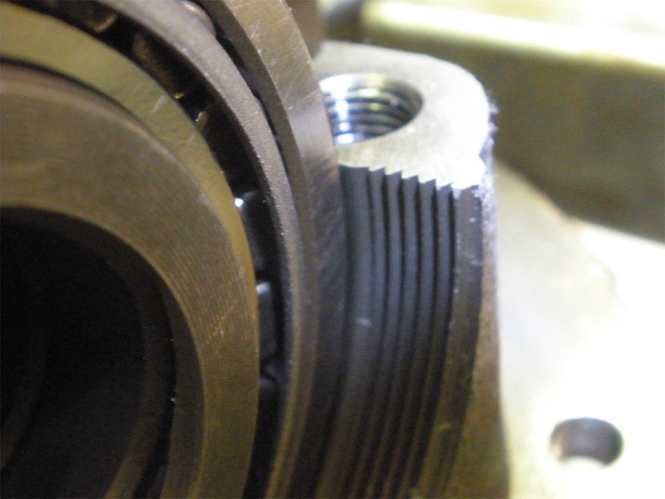
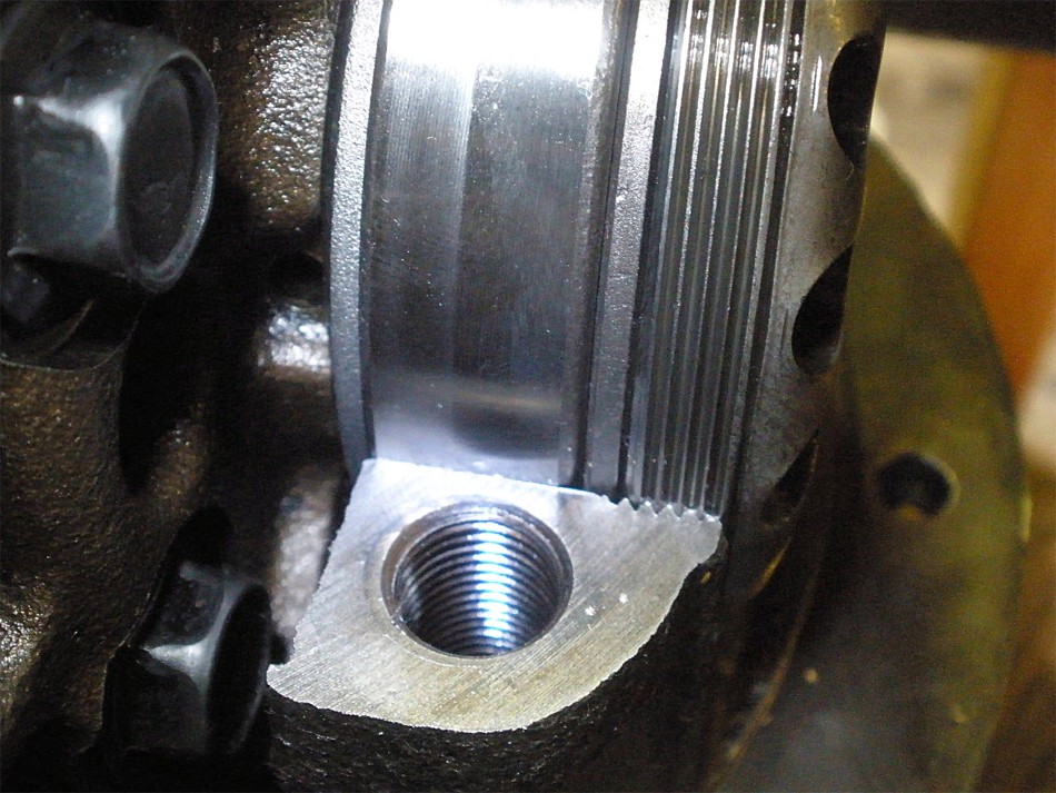
This side has the minimal required amount of thread engagement just like the
usual Supra LSD install in a V6 3rd.
|
|
|
|
These are the common washer plates used in 4 cyl IFS front carriers to set
carrier bearing preloads and backlash....
|
|
|
|
|
...a perfect fit here.
|
|
|
|
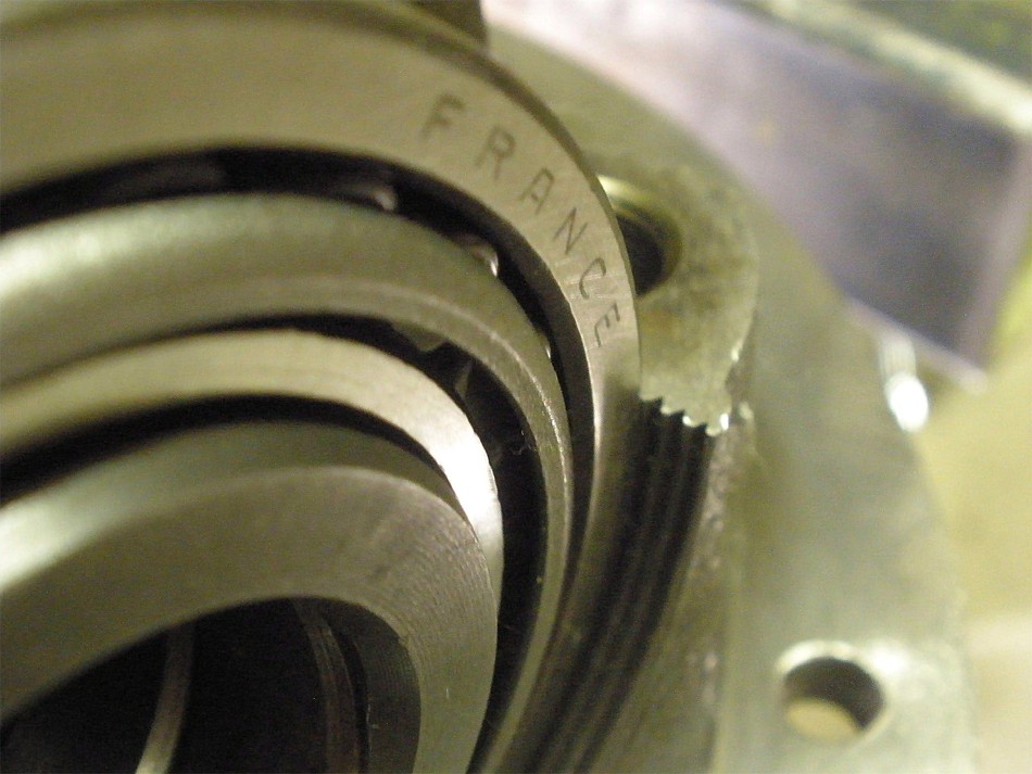
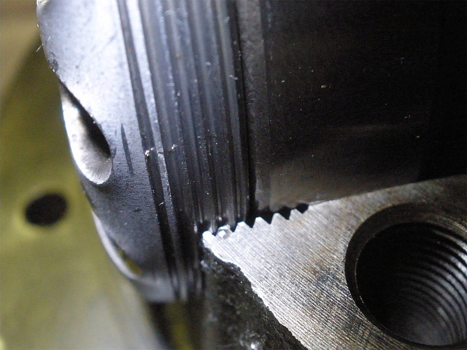
Another shot of the other side. It doesn't seem like alot of thread engagement
but it is 'enough'. Fortunately, because of the way the pinion pushes on the
ring gear means that it's the other side that sees most of the axial loads...
and it's the other side that has 100% thread engagement and then some.
|
|
|
|
|
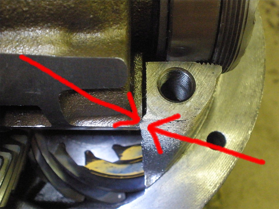
Clearances are aok on this side.....no touch up needed.
|
|
|
|
|
Now, the other side, does need some minor touchup.
|
|
|
|
|
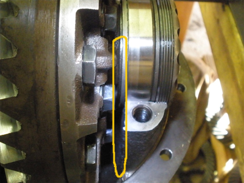
The ragged edge on the casting made contact here.
|
|
|
|
|
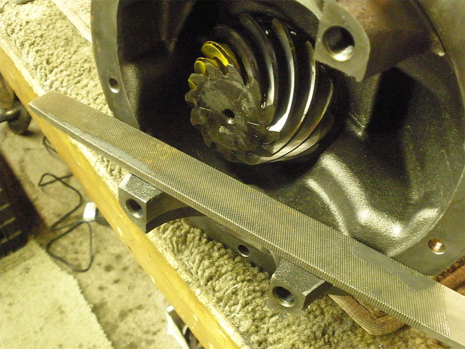
A large course file took care of that in 10 seconds.
|
|
|
|
|
The file easily removed the lip.
|
|
|
|
|
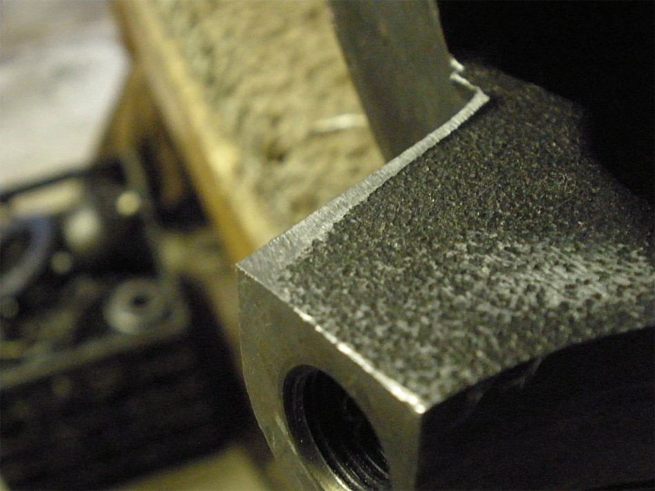
The other side was left alone as the lip caused no issues.
|
|
|
|
|
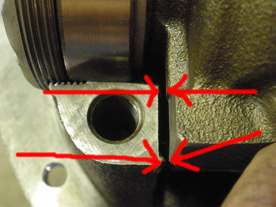
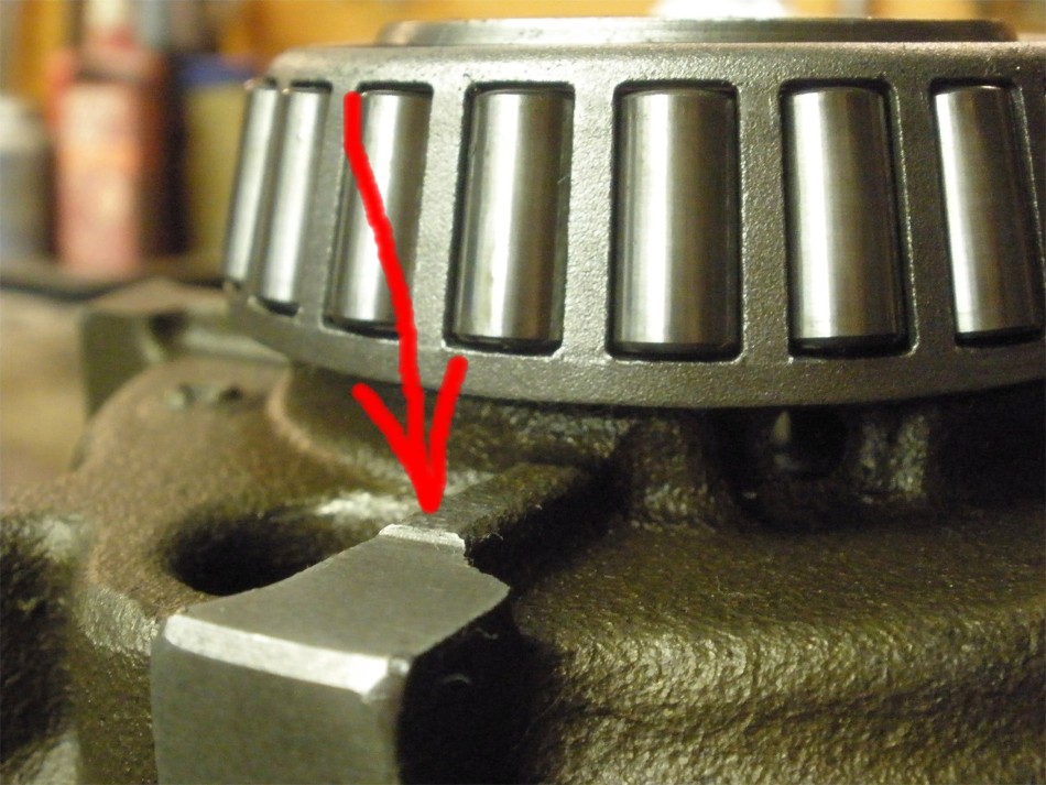
There was one other area of close contact.
|
|
|
|
|
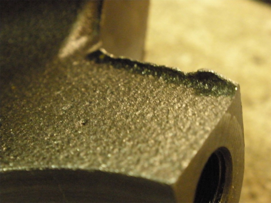
This little raised edge needed some touchup...
|
|
|
|
|
...and it was very easy to do with the corner of a cutting wheel
|
|
|
|
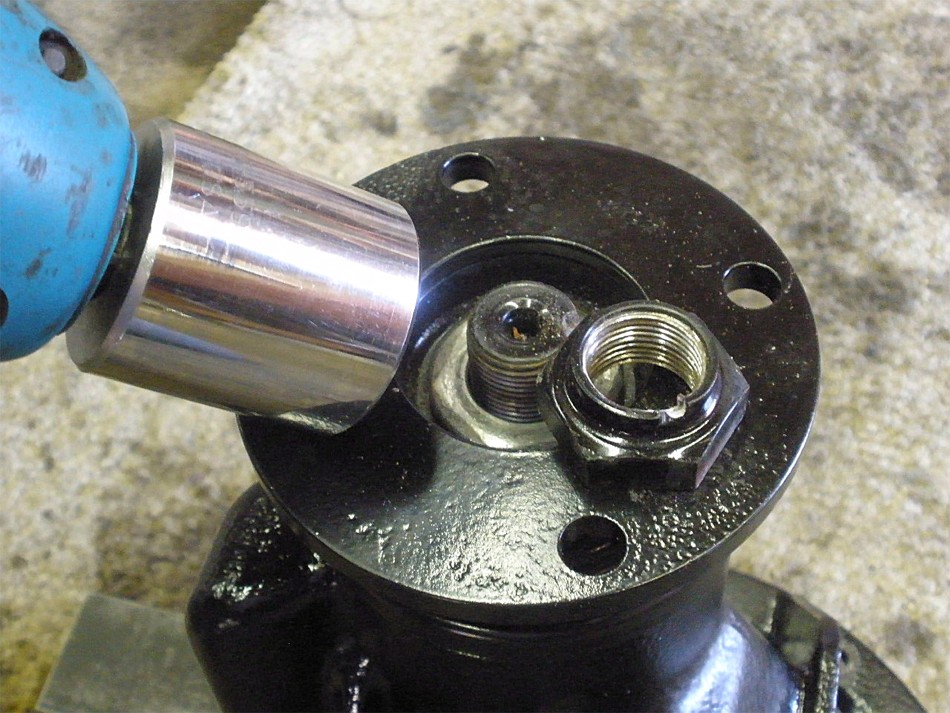
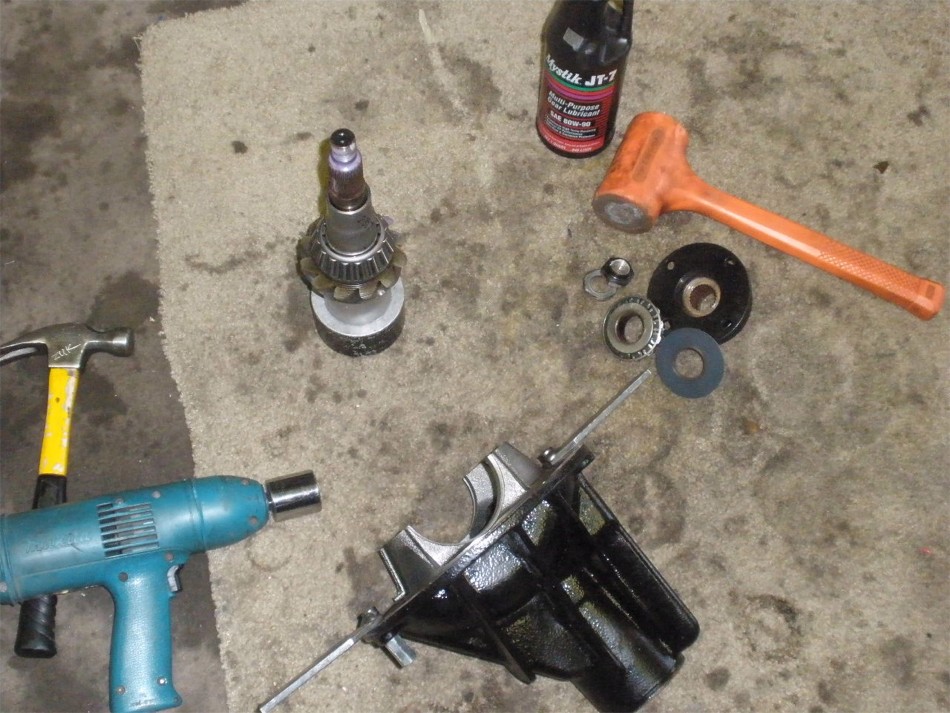
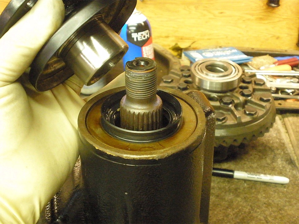
With that done, now it's time to teardown the pinion end to inspect the
bearings, use a new crush sleeve , and a new seal. The electric impact
easily removed the pinion nut shown here.
|
|
|
|
The flange is cleaned up and hit with some 1000 grit sandpaper. The seal
surface appears ok for re-use.
|
|
|
|
|
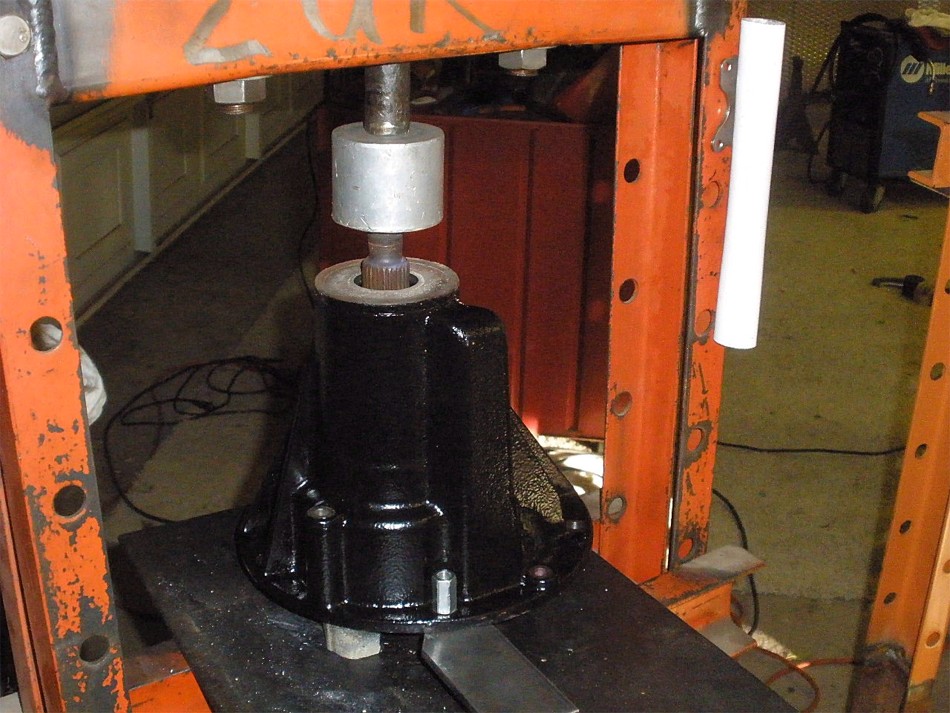
Push the pinion out.
|
|
|
|
|
This OEM V6 crush sleeve and seal will now be installed.
|
|
|
|
|
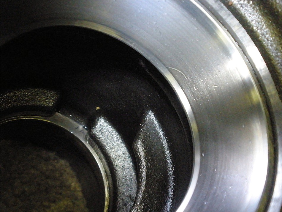
Bearings appear ok for re-use.
|
|
|
|
|
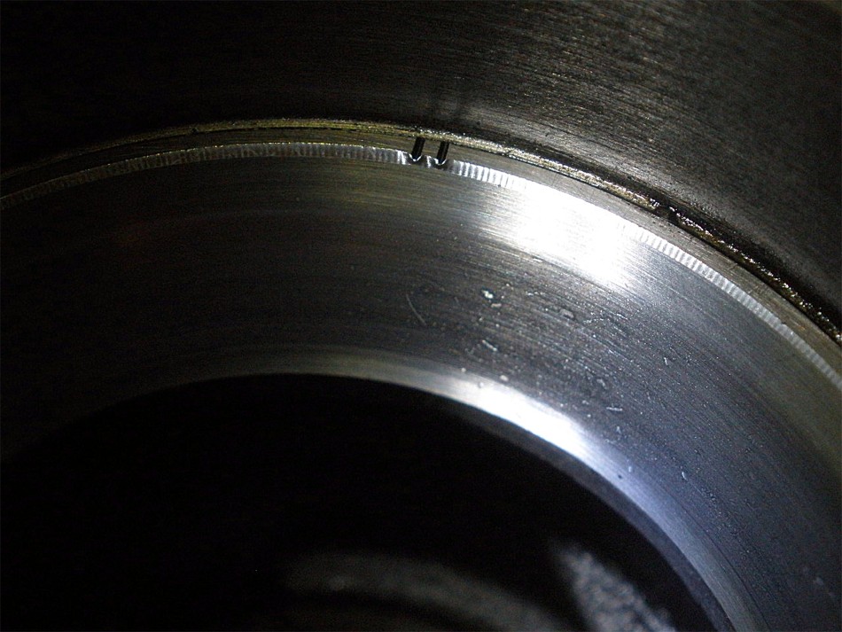
The small outer race has some pitting.
|
|
|
|
|
The large inner race also has some pitting.
|
|
|
|
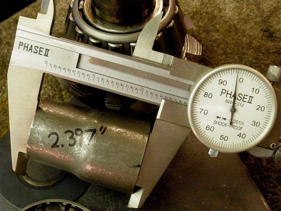
Using my mini-lathe, I trimmed off about .080" for a new length of 2.397" and
since the final crushed length will be very close to 2.382" means that I will
have to crush for only about a quarter of a turn of the pinion nut and this
saves on pinion nut thread damage effectively.
|
|
|
|
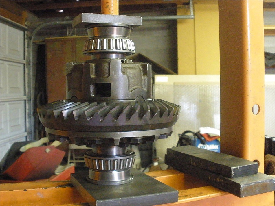
The pinion assembly is placed on the 2 aluminum pucks, main 3rd carrier is
placed on top of the pinion, bearing and flange are then tapped on using the
lead filled plastic hammer. The electric impact can then tighten the nut but
not quite enough to cause the sleeve to crush at all.
|
|
|
|
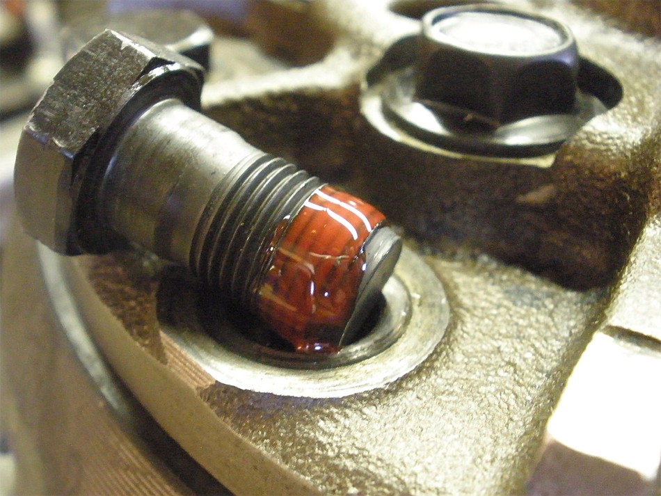
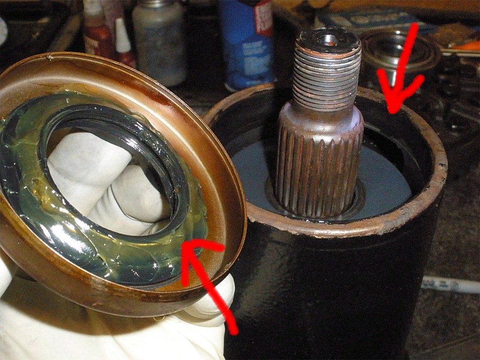
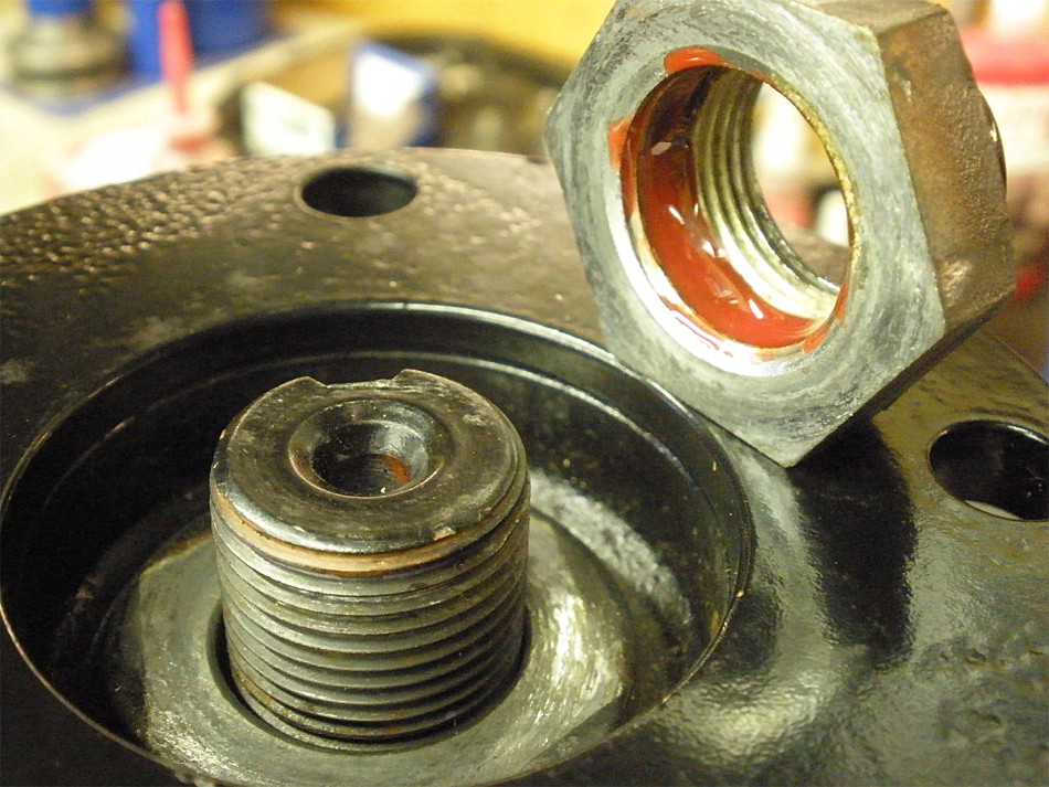
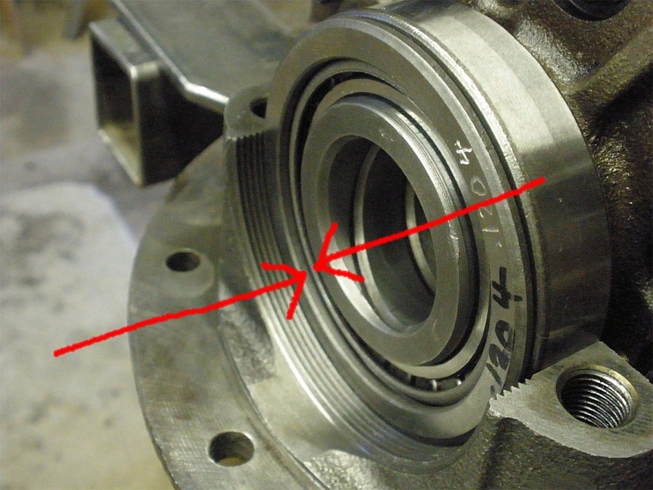
A heavy grease is applied to the seal insides to prevent the spring from
popping off. This has proved very effective for me. Probably not required
but I also use rtv where the upper red arrow is pointing. I think it seals
the metal to metal surface contact a little better and also helps with tapping
the seal in place a little easier.
|
|
|
|
|
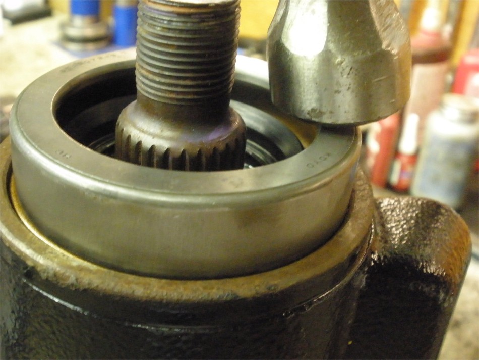
The seal tool makes quick work of this.
|
|
|
|
And then I use an old race to tap the seal another millimeter down per the
book spec.
|
|
|
|
|
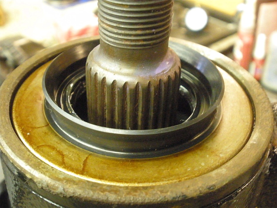
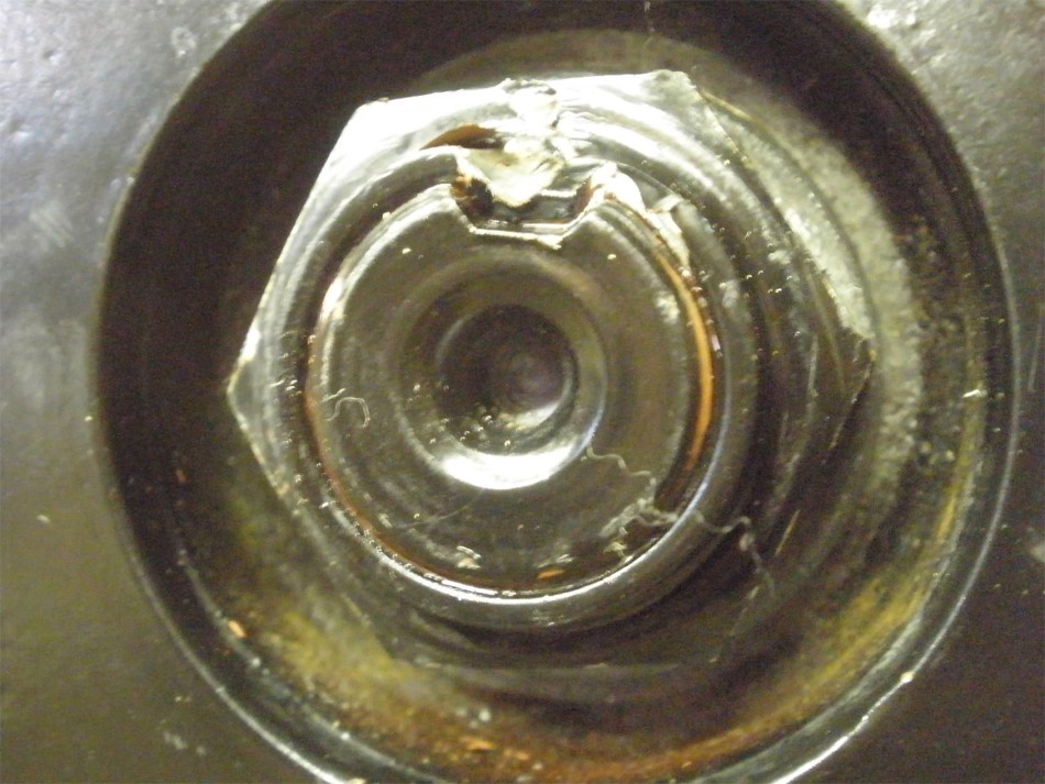
A correctly installed seal.
|
|
|
|
|
More gear oil is smeared on the related seal surfaces and on the flange.
|
|
|
|
|
Red loctite.
|
|
|
|
|
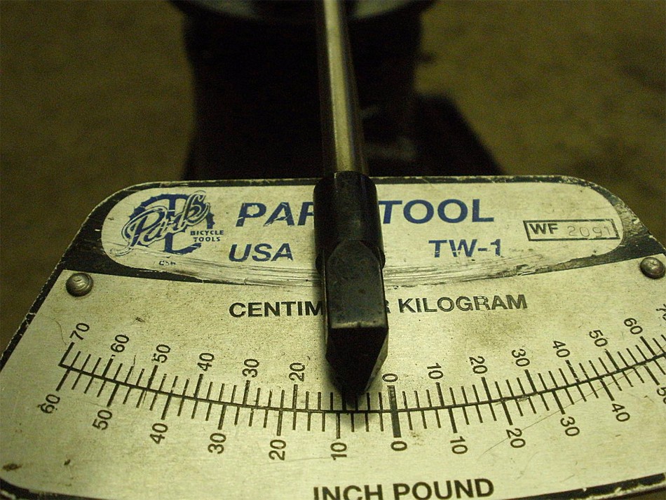
And barely a quarter of a turn...
|
|
|
|
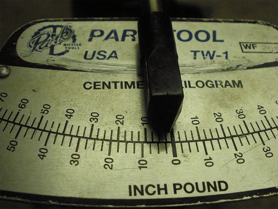
...produces 8 inch/pounds of start torque reading. These are used bearings so
8 is a safe number.
|
|
|
|
I also measured the rolling torque at about 2 inch/pounds based on a 1
revolution per second rate. Rolling torque and start torque readings
vary widely depending on new bearings verses old verses wear. I trust
start torque because that's what most manuals seem to call out.
|
|
|
|
DING and this end is complete. Must have had poor lighting for a picture of
this quality :)
|
|
|
|
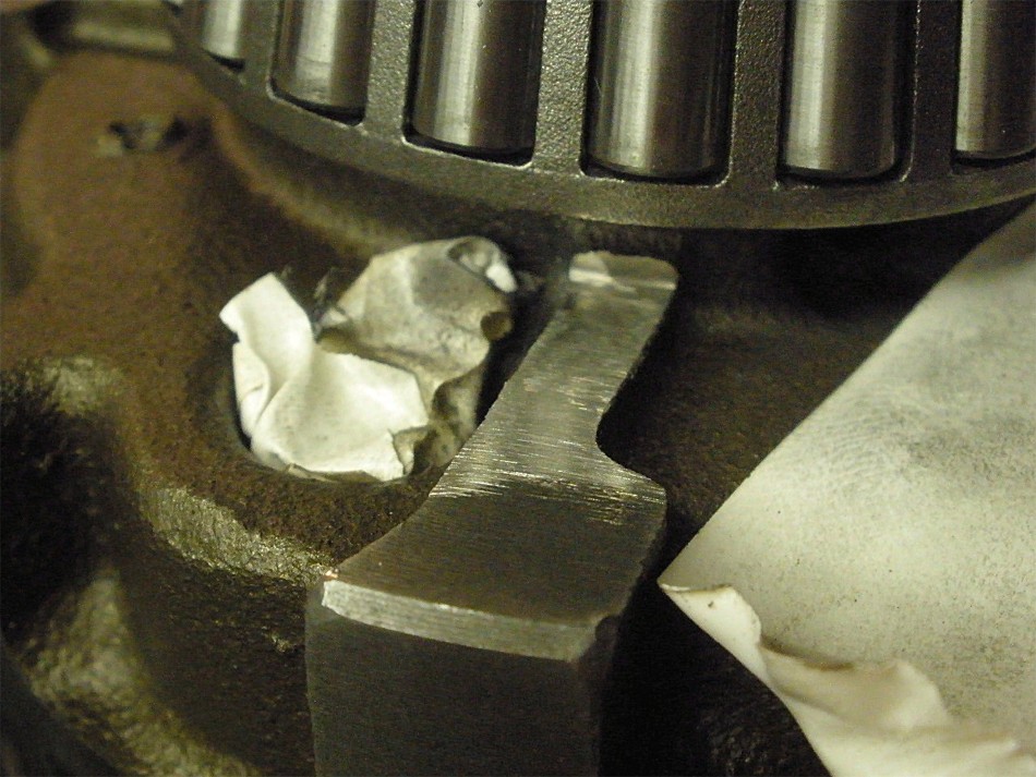
It turns out the bearing cage was causing some interference contact here...but
nothing that a little clearancing on the inside of the washer plate couldn't fix.
|
|
|
|
I use the rubber end of the hammer to tap the bearing caps down. A solid
SNAP! noise tells me the threads were all properly aligned.
|
|
|
|
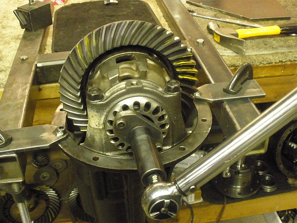
Done correctly, I can tighten the 4 bearing cap bolts to 75 ft/lb and the wheel
adjusters will easily turn with just 2 of my fingers.
|
|
|
|
|
I torqued it to a modest 75 ft/lbs here.
|
|
|
|
|
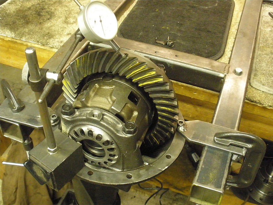
Backlash was checked on every 3rd tooth and was averaging in at .008"
|
|
|
|
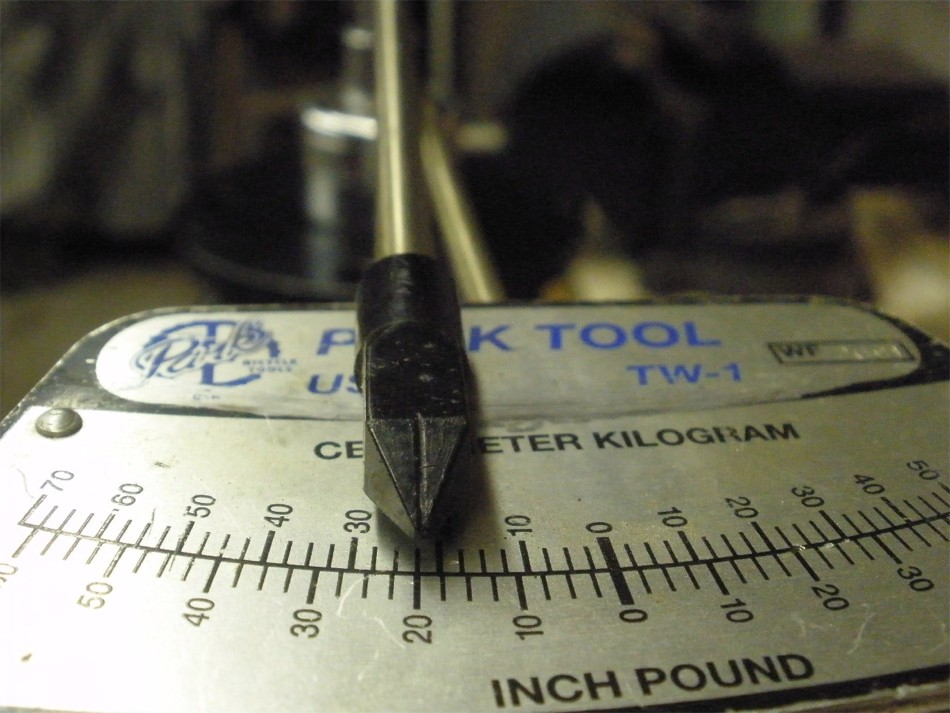
Measuring the starting torque required to turn both the pinion and carrier
bearings measures in at 20 inch/pounds. This shows that I have good pre-load on
the carrier bearings. 8 of those inch/pounds are to turn the pinion...doing the
math, that leaves us with 12 to turn the carrier bearings.
|
|
|
|
|
Final pattern check....the drive looks great....deep and slight toe.
|
|
|
|
Coast is also nicely centered. These are used gears, of course, and the
factory pinion shim was not disturbed.
|
|
|
|
12 teeth on the pinion and 41 on the ring....3.42 gears that are found on some
2wd trucks.
|
|
|
|
|
|
|
|
|
|
|
|
|
|
|
|
|
|
|
|
Done :)
|
|
|

|