|
|
|
|
|
|
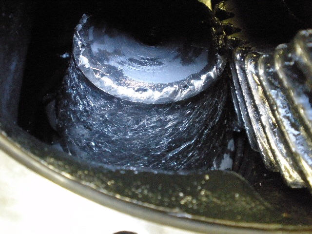
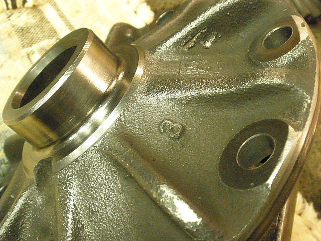
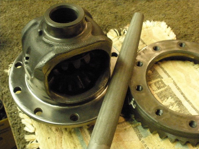
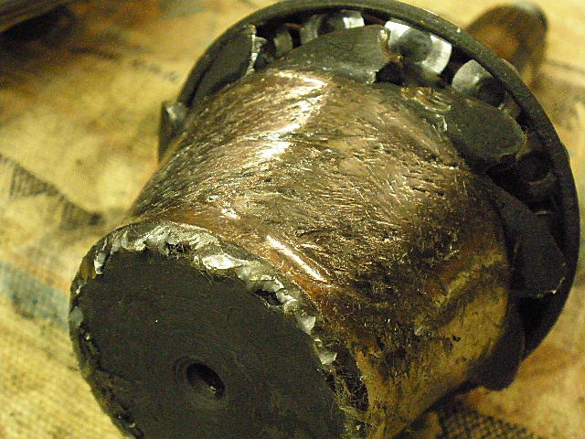
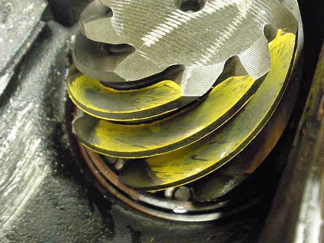
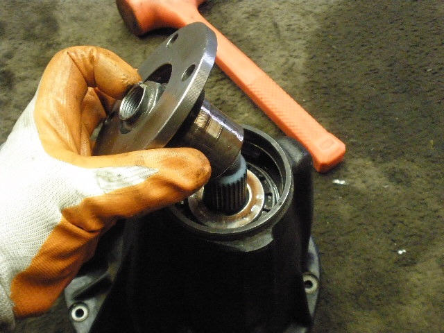
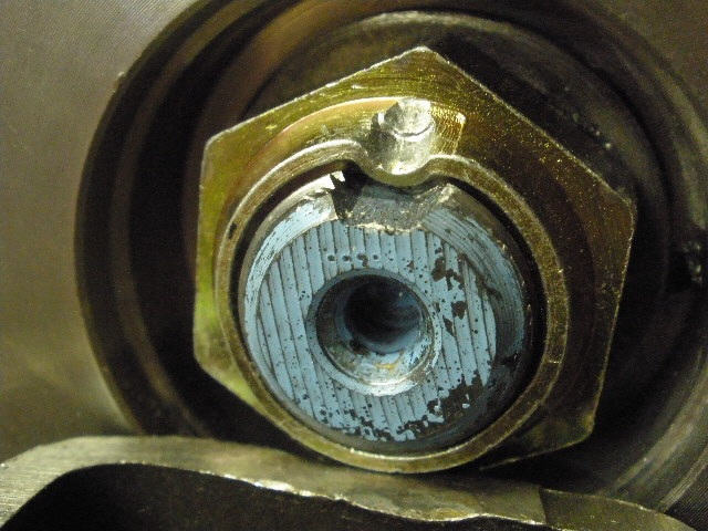
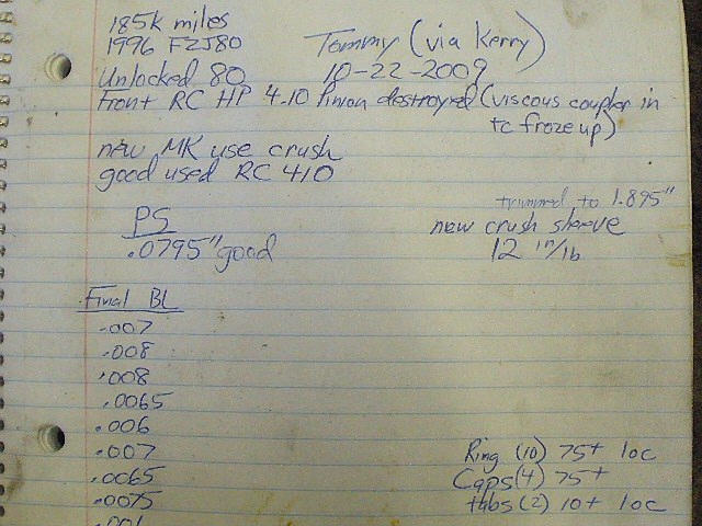
Tommy purchased this sweet 1996 FZJ80 from New Mexico and while driving it home on the freeway started to get a loud rumble from the front end. The viscous coupler in the transfer case was believed to be mal-functioning and tried to lock up....the result was tremendous resistance as felt by the ring and pinion contact and tremendous heat. The pinion has no place to dissipate heat and probably got close to cherry red. The ring gear is a larger surface area and was able to dissipate the heat to the case and the oil thus less damage to the ring gear. |
|
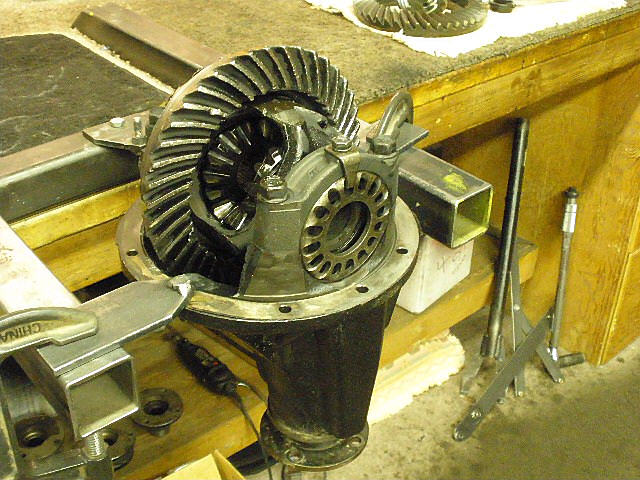
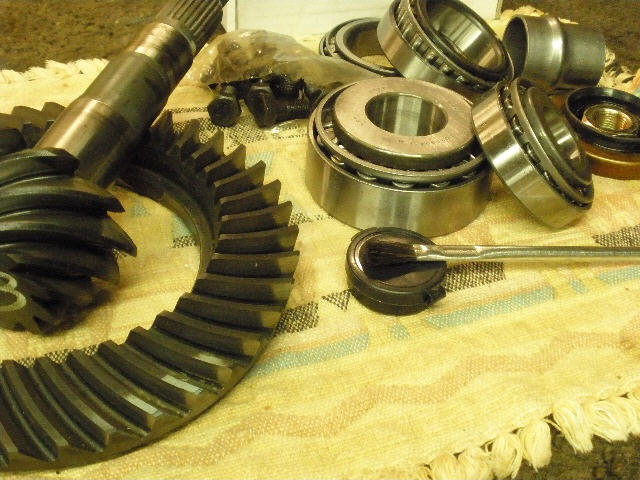
8" hi-pinion reverse cut gears... |
|
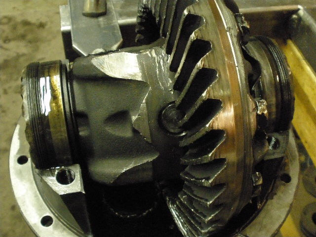
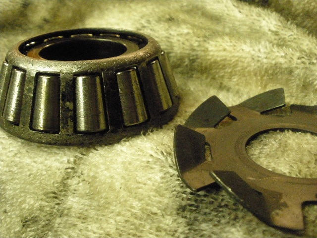
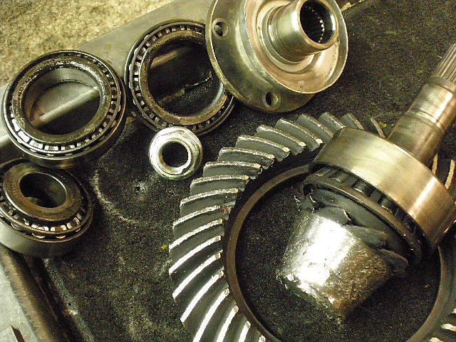
With all that metal floating around in the oil, the bearings wore unusually fast...no pre-loads felt at all as expected. |
|
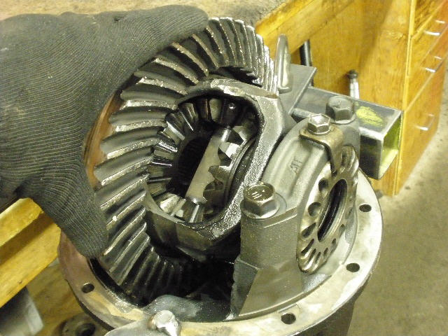
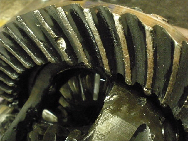
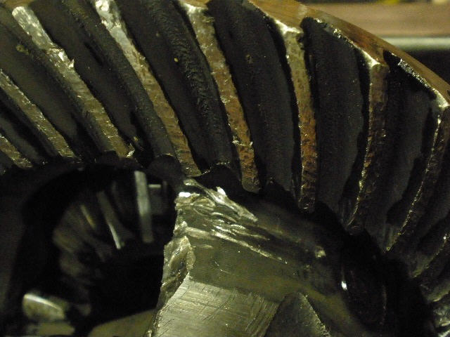
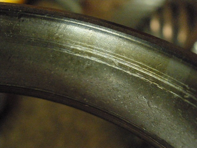
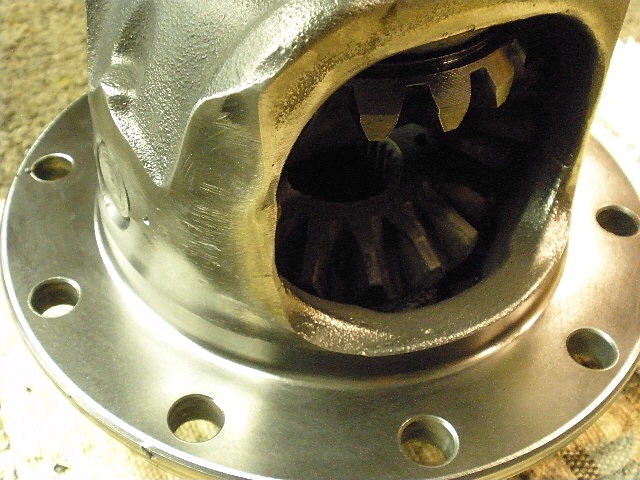
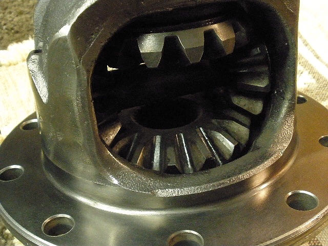
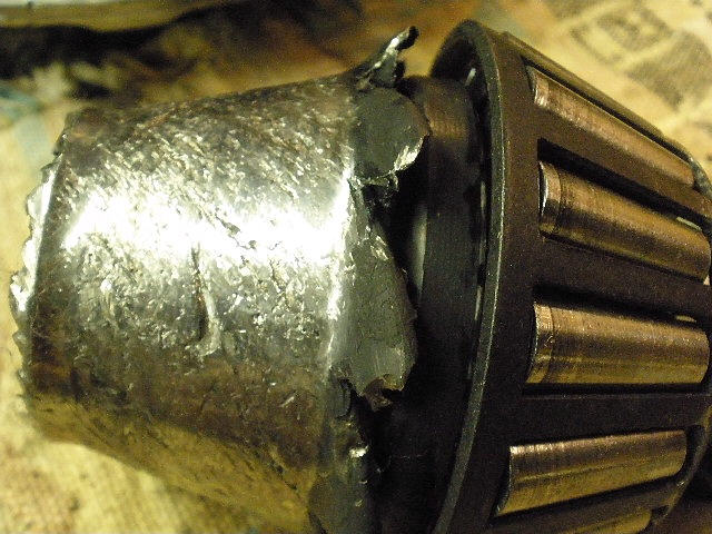
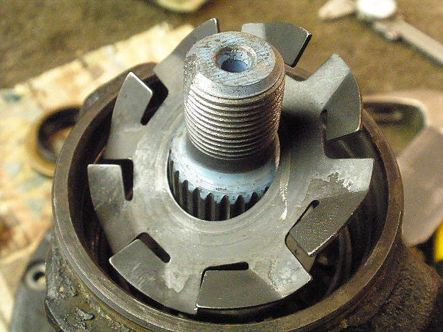
The teeth look pretty hammered. |
|
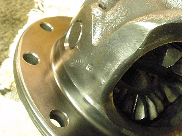
The case also looks like chunks of teeth had smashed into it. |
|
It took some major heat to do this kind of damage. |
|
A used 410 reverse-cut ring/pinion and a new master install kit will be installed. |
|
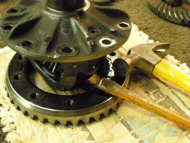
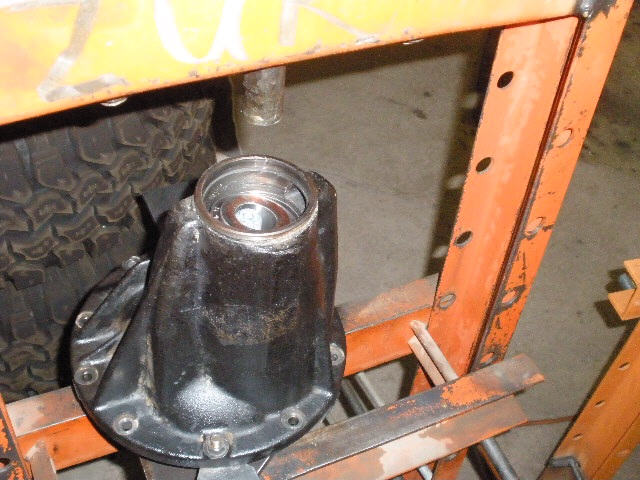
The teardown begins...caps are removed and the case comes out. |

|
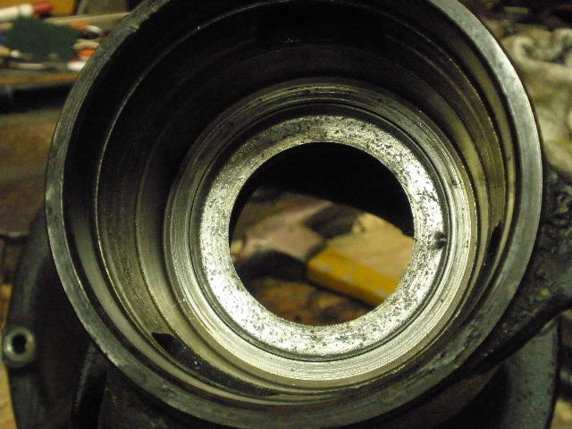
As expected, the carrier bearing races are garbage with all the metal that was swimming around. |
|
``` |
|
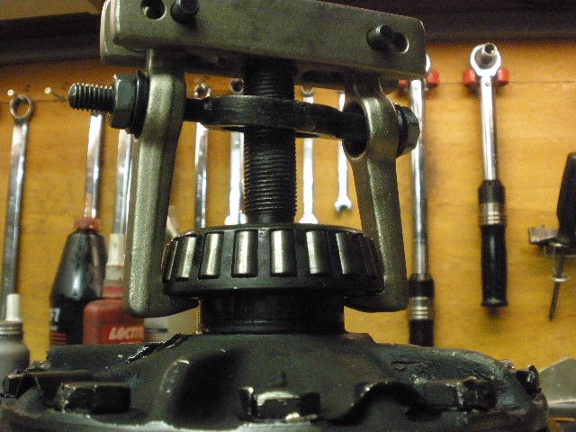
Bearings are removed with the right tool. |
|
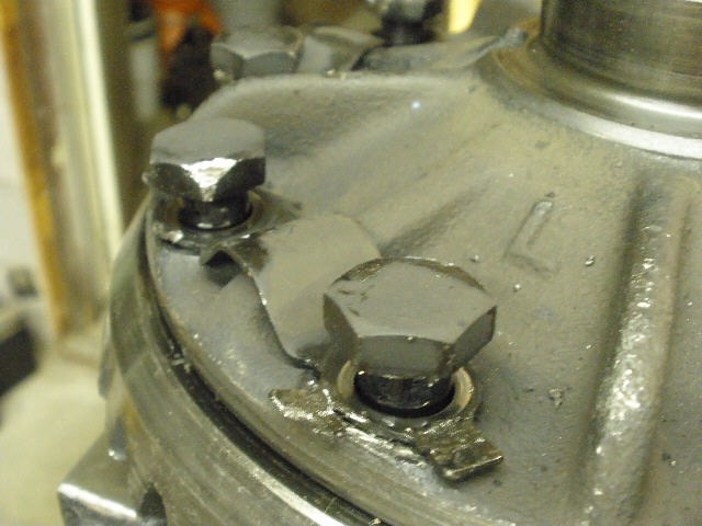
Ring gear bolts go in the garbage... |
|
...as will the ring gear. |
|
Rough edges are removed with a flapper wheel. |
|
My bench mounted wire wheel did a very nice job on the metal surface also. |
|
``` |
|
The flapper wheel removed almost all of the deep gouges. |
|
The file checks the mounting surfaces for burrs/raised edges and all was well. |
|
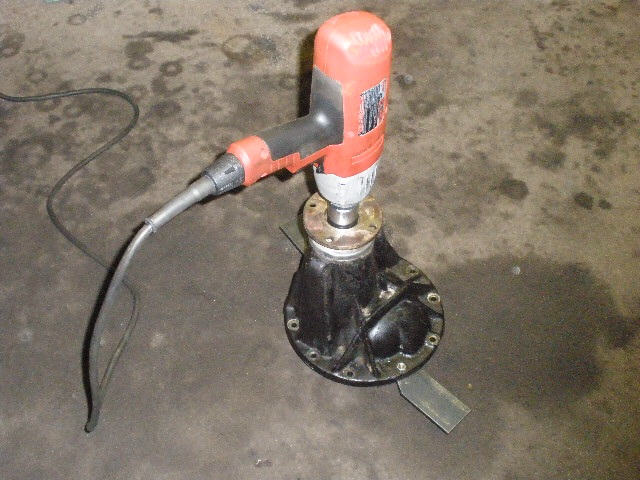
The 30mm pinion nut easily comes off with the electric impact. |
|
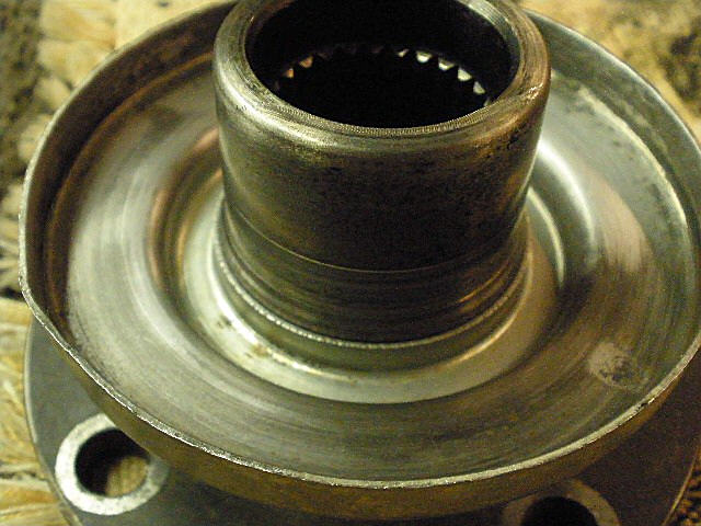
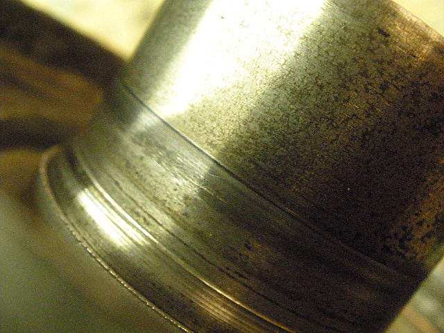
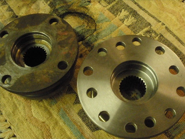
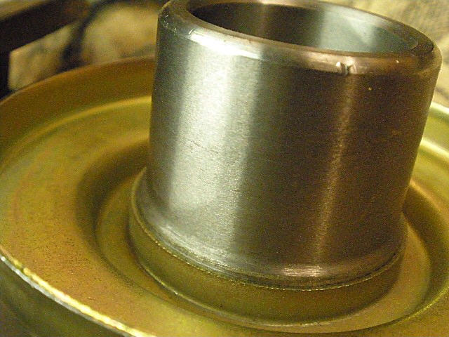
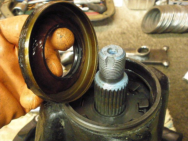
The flange's seal surface looks pretty rough. |
|
``` |
|
A new triple drilled flange will be added at the very end of this install. |
|
``` |
|
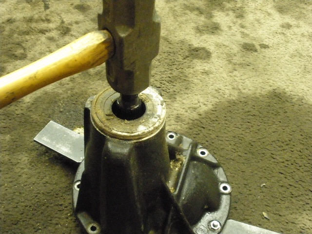
I'm not worried about thread damage on this gem so the big hammer can now do its job. |
|
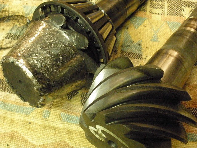
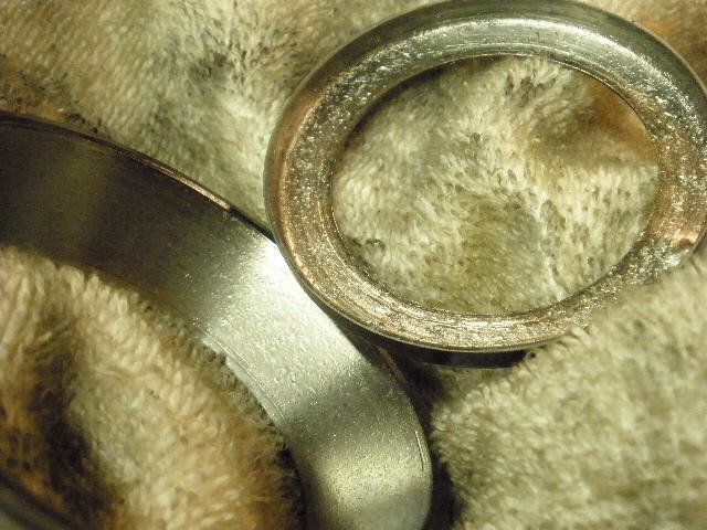
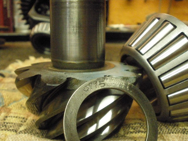
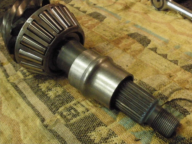
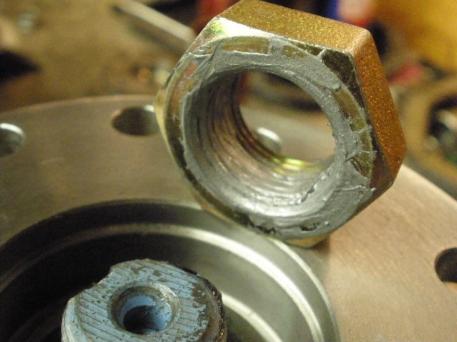
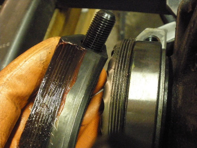
The old pinion up against its replacement. |
|
That's some major tooth damage there. |
|
``` |
|
The old outer pinion bearing and the oil slinger commonly found on high pinions. |
|
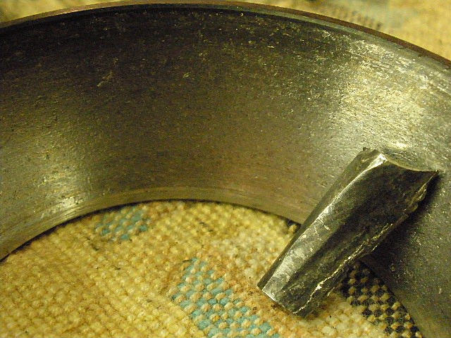
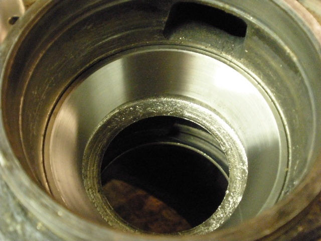
This is the severely scarred large inner race with a piece of tooth that was found nearby. |
|
The smaller outer race and the oil retainer. The oil retainer saw some metal scrubbing but is still 100% functional. |
|
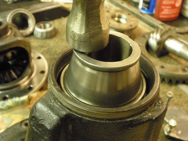
The inner race is pressed in. |
|
The oil retainer is tapped in place... |
|
...followed by the outer pinion race. |
|
... |
|
Both carrier bearings are pressed on at the same time. Both were a tight fit onto the journals so no sleeve-lock compound was needed. |
|
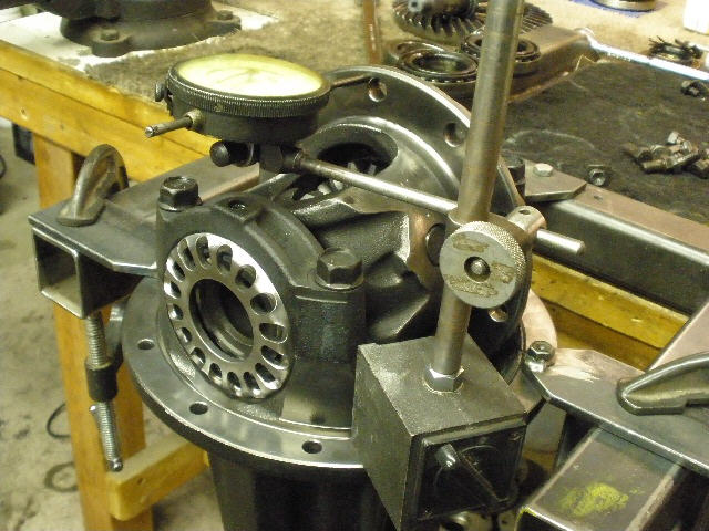
The burnt on oil residue on the case was an indication of the tremendous heat involved so a quick check for run-out revealed almost none...just a little over .001". |

|
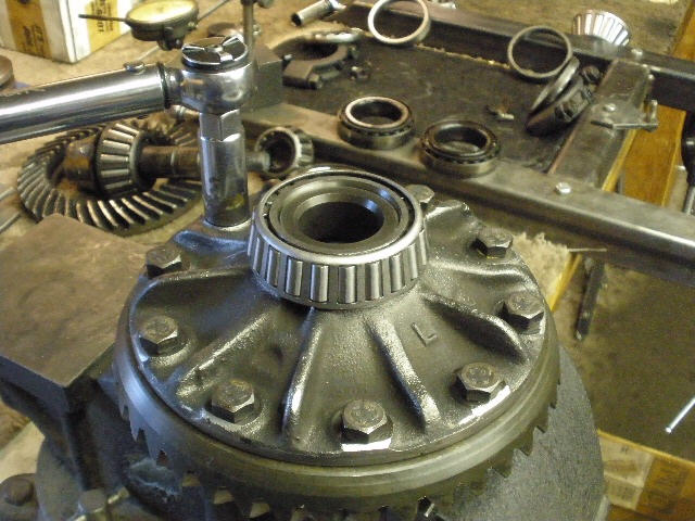
Now the ring gear can be put on. Red locktite on all 10 of them. |
|
70~75 ft/lb |
|
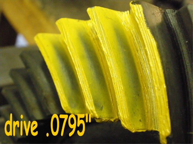
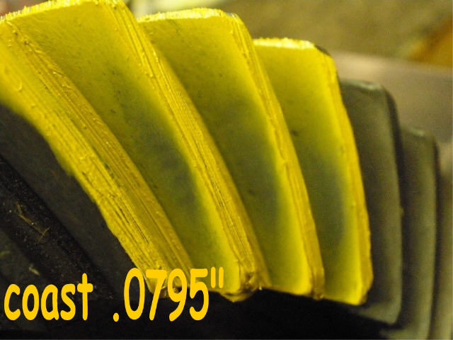
Now to the pinion end...a .0795" shim is a common shim to use in this application. |

|
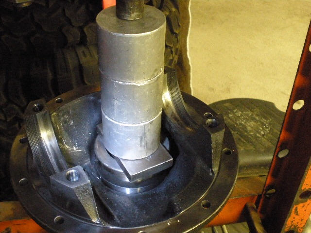
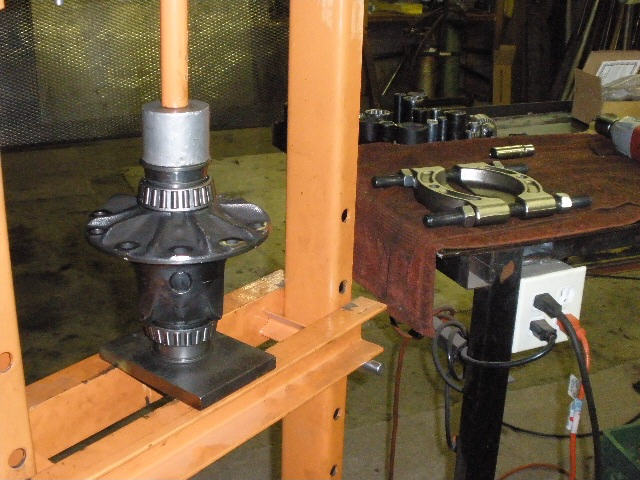
The new bearing is pressed on with the 12 ton press. |
|
The pinion nut can now be tightened until something in the range of 10~15 inch/pounds in drag is measured. The crush sleeve has been left out until proper depth has been confirmed. |
|
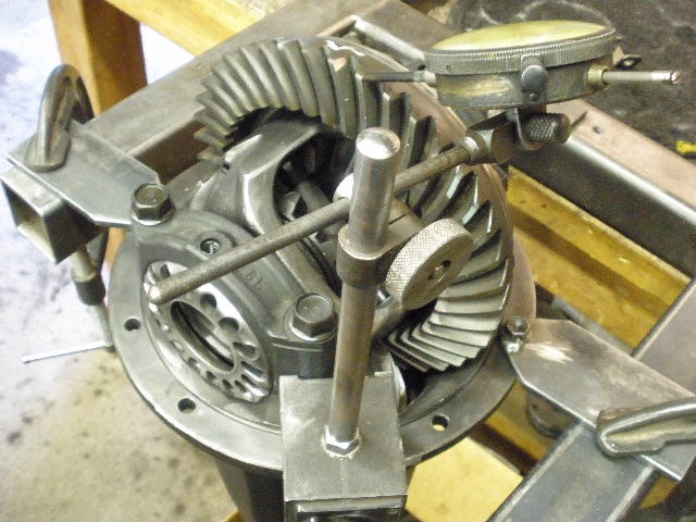
Now the case end can be installed. The 4 cap bolts are hand tightened. |
|
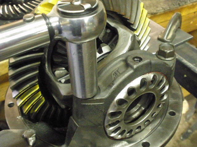
The backlash is adjusted to about .008" while some pre-load is added at the same time. |
|
These are used gears so the pattern may be harder to see...especially on the much used drive side. |
|
Coast looks ok. |
|
Looking at some of the other teeth that were reverse painted, the drive looks ok. |
|
Coast ok. |
|
Pinion confirms a good depth. It doesn't happen this way all the time where the first pinion shim looks good. Used gears can take longer than new gears to set up sometimes. |
|
Happy with the pinion depth, now the pinion is pushed out. |
|
Now the new crush sleeve can be installed. |
|
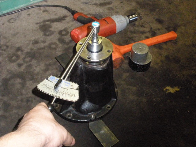
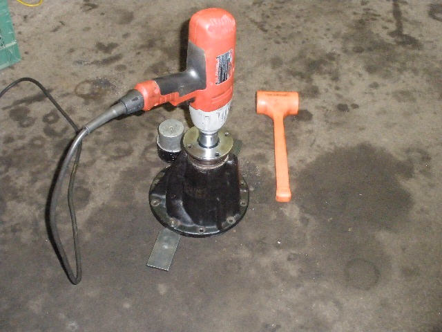
My electric doesn't generate enough torque to crush the sleeve but it does pull it on far enough... |
|
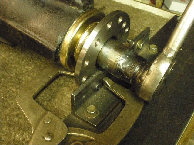
...where I can remove my shop flange and the pinion won't drop out while the rest of the top end stuff is installed. |
|
The slinger drops on... |
|
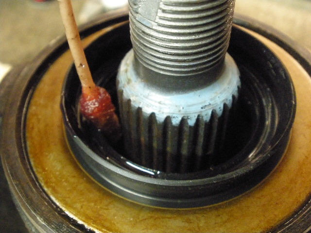
...and the seal is prepped and tapped in place. |
|
Some gear oil is applied to the seal surface to prevent a dry start-up condition. |
|
Since I am using a crush sleeve and this particular pinion nut is a 'jam nut'(egg shaped hole) then I will apply anti-seize to minimize thread resistance. |
|
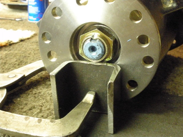
This fixture locks the flange down while I put tremendous pressure on the nut. |
|
The anti-seize did its job as I was able to crush the sleeve without too much difficulty. It's also good to have some leverage in these situations. |
|
I then support the underside of the nut and ding the top of the jam nut with a rounded chisel. |
|
I don't think the jam nut was designed to be dinged like this...but it works out nicely. |
|
Threads are liberally greased up and carefully meshed together. |
|
I admit that I do use the hammer alot...but I like to send some shock wave to help align the upper thread assembly to the lower while slowly snugging up on the cap bolts. Then I can fully tighten the 4 cap bolts to the full 70~75 ft/lb spec. Then I find that I can turn the adjuster wheels easily with just finger pressure which is an indication that the threads are not mis-matched. |
|
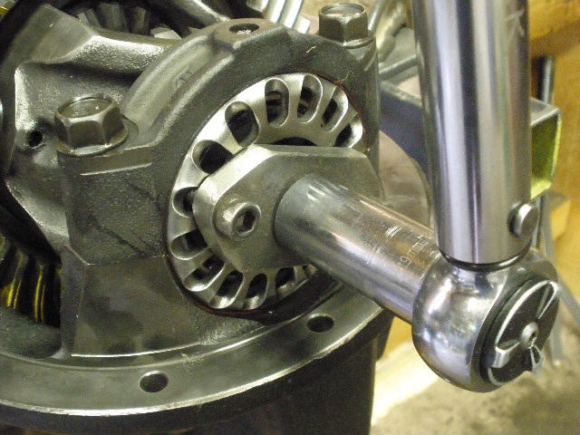
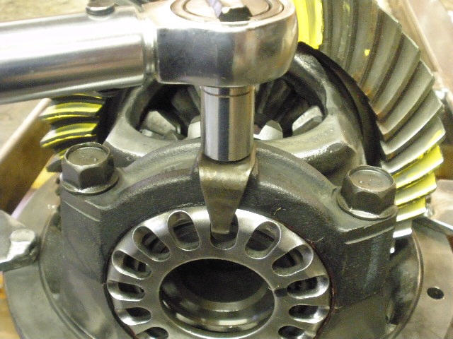
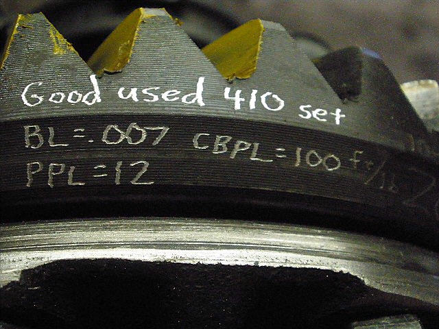
Backlash is dialed in and both caps are tightened to 100 ft/lb. 100 ft/lb on the adjuster wheels translates into 10 inch/pounds of actual bearing rolling resistance. |
|
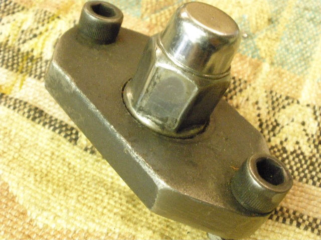
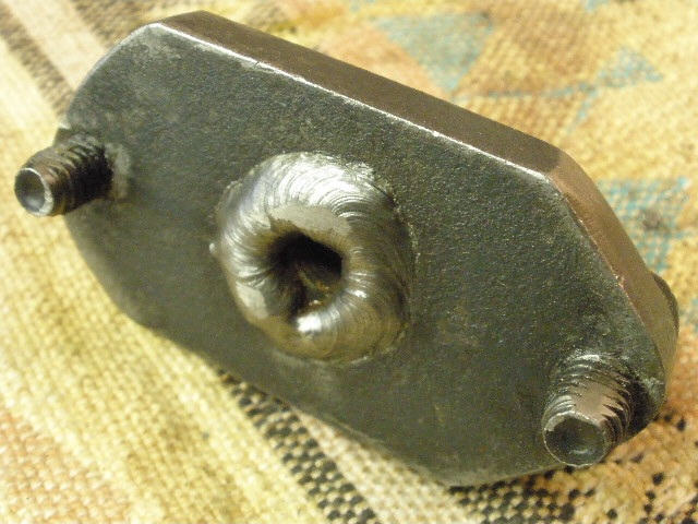
I made my own wheel adjuster 'socket'...a little drilling, tapping, and welding. |
|
``` |
|
Lock tabs have red loctite on them and they are then tightened to 10 ft/lb (120 in/lb). |
|
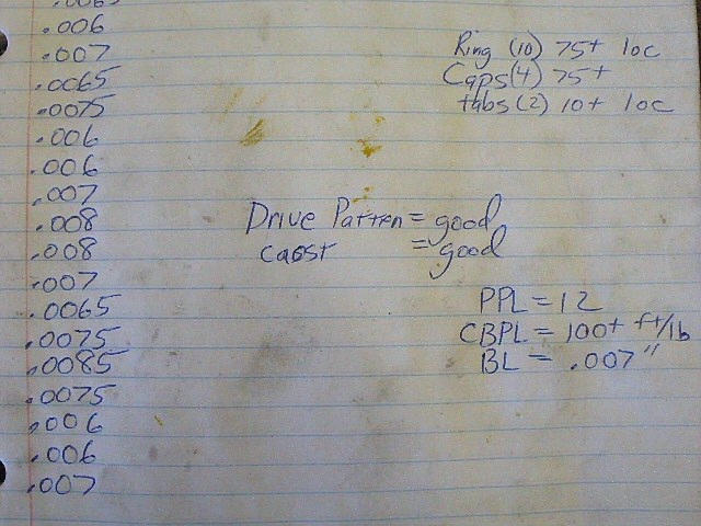
Backlash is recorded on every other tooth for about 21 measurements. Final BL was .007". |
|
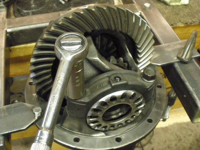
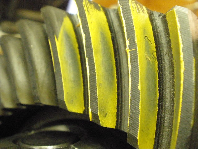
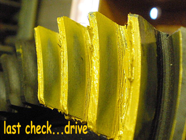
Hard to see the actual pattern even though I apply plenty of resistance on the pinion end while I turn the ring gear back and forth 3 times with a 17mm wrench. |

|
Coast is good. |
|
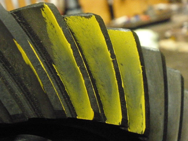
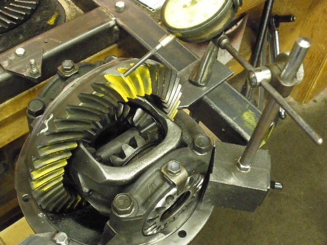
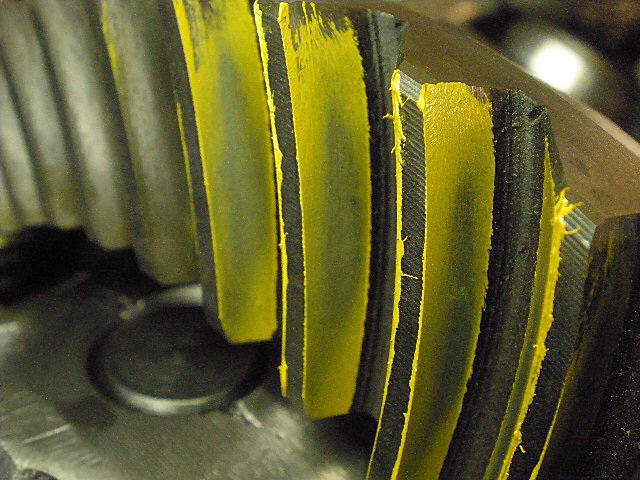
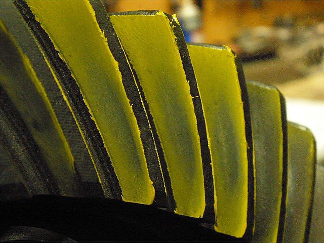
The reverse painted teeth show the drive pattern better. Looks good. |
|
Coast is ok here also as expected. |
|
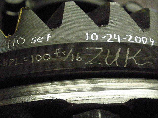
I document some of the important settings on the ring gear. |
|
``` |
|
``` |
|
``` |
|
``` |

|