|
Installing a Supra 8" LSD into a "4 cylinder" 3rd and clearancing it
|
|
(99 BIG pics loading)
|
|
Feb 14 2015
|
|
|
|
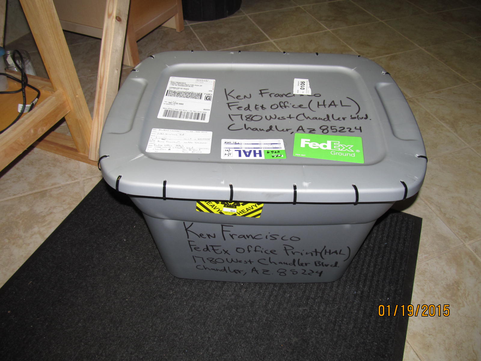
As received from Mike...plenty of tie-raps.
|
|
|
|
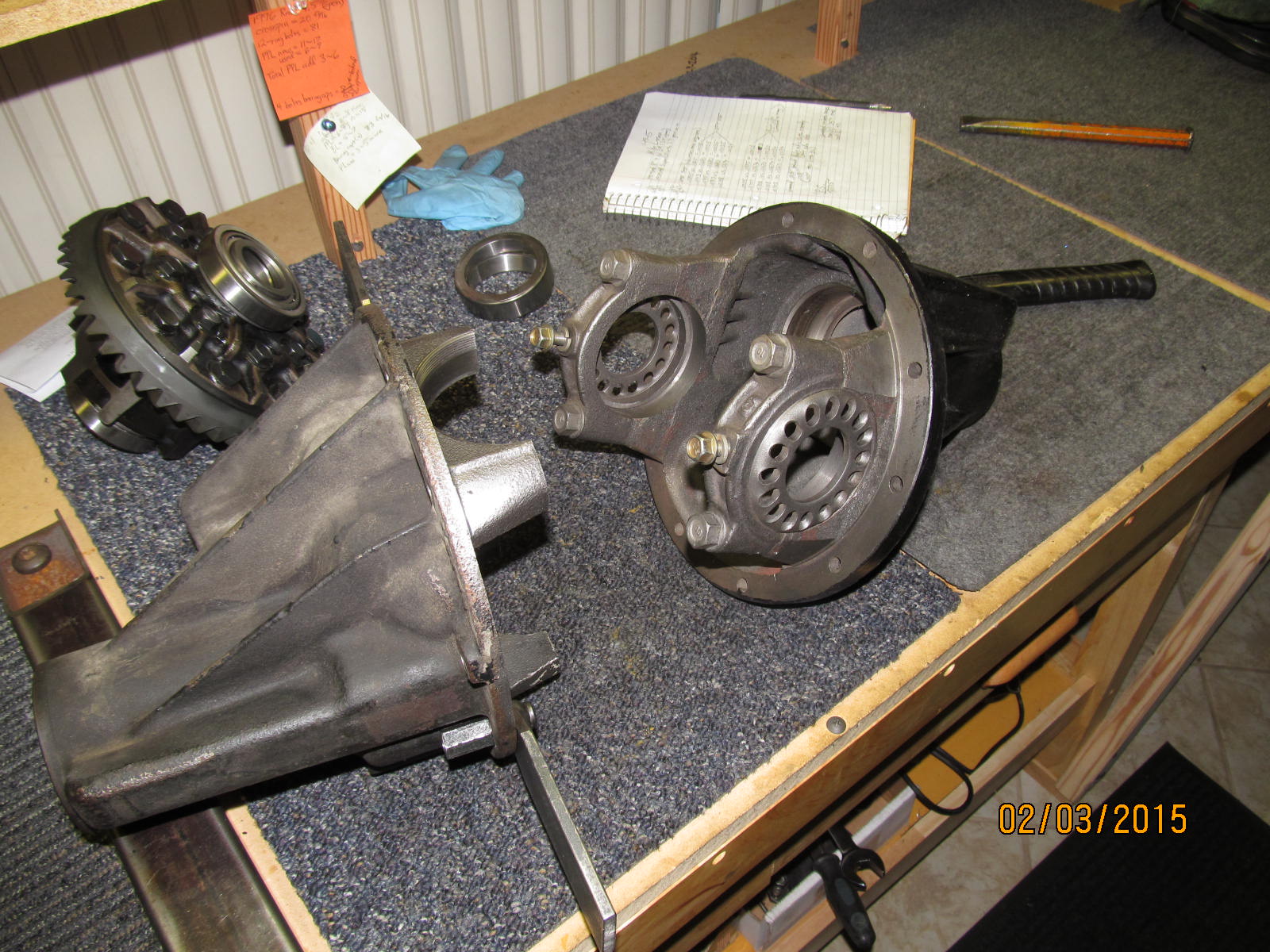
In the tote was Mike's "4 cyl 3rd" with the low ratio 3.42 gears. Also sent was the SupraLSD with 3.90 gears
shown in the background.
|
|
|
|
|
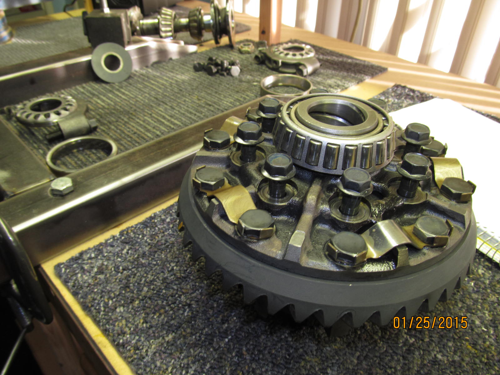
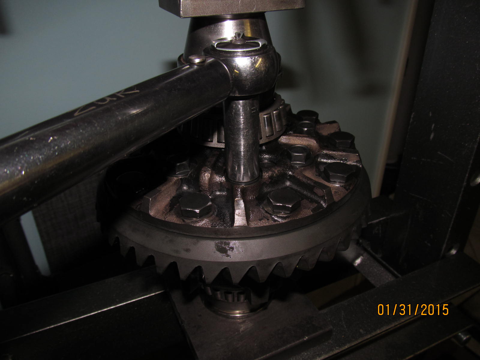
Dis-assembly begins...removing the 8 long bolts that hold the LSD case together.
|
|
|
|
|
....
|
|
|
|
|
......
|
|
|
|
|
.....
|
|
|
|
|
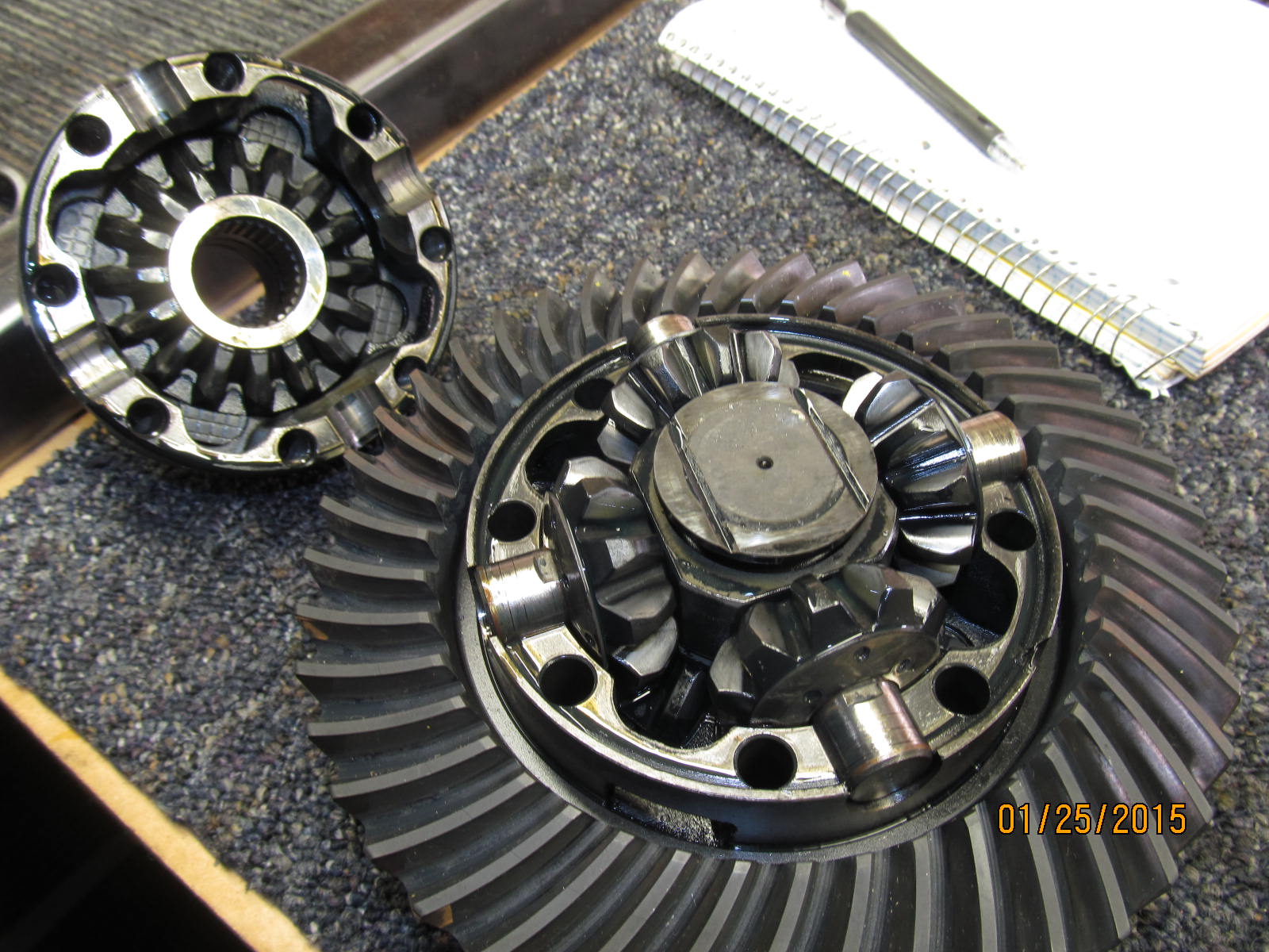
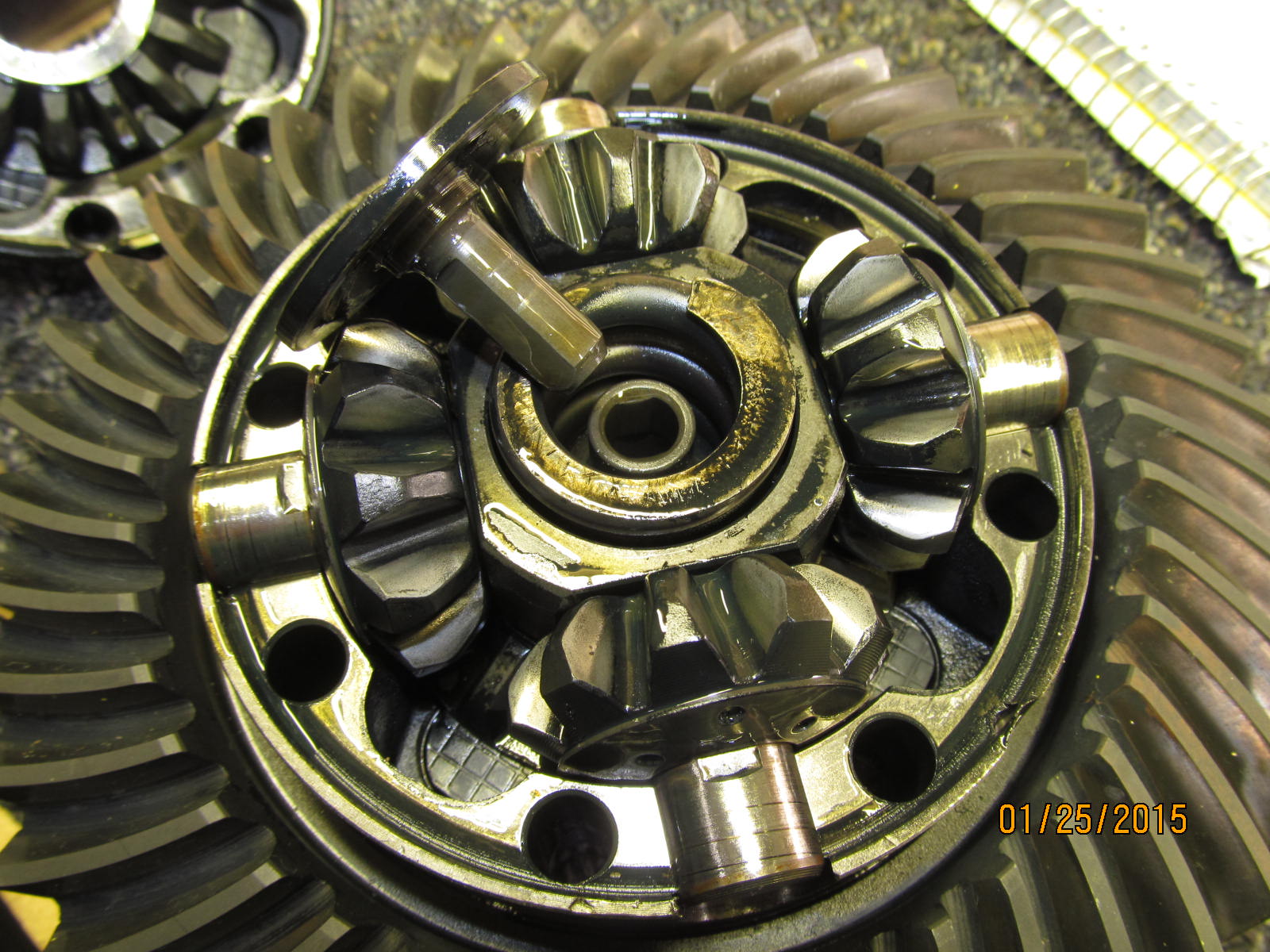
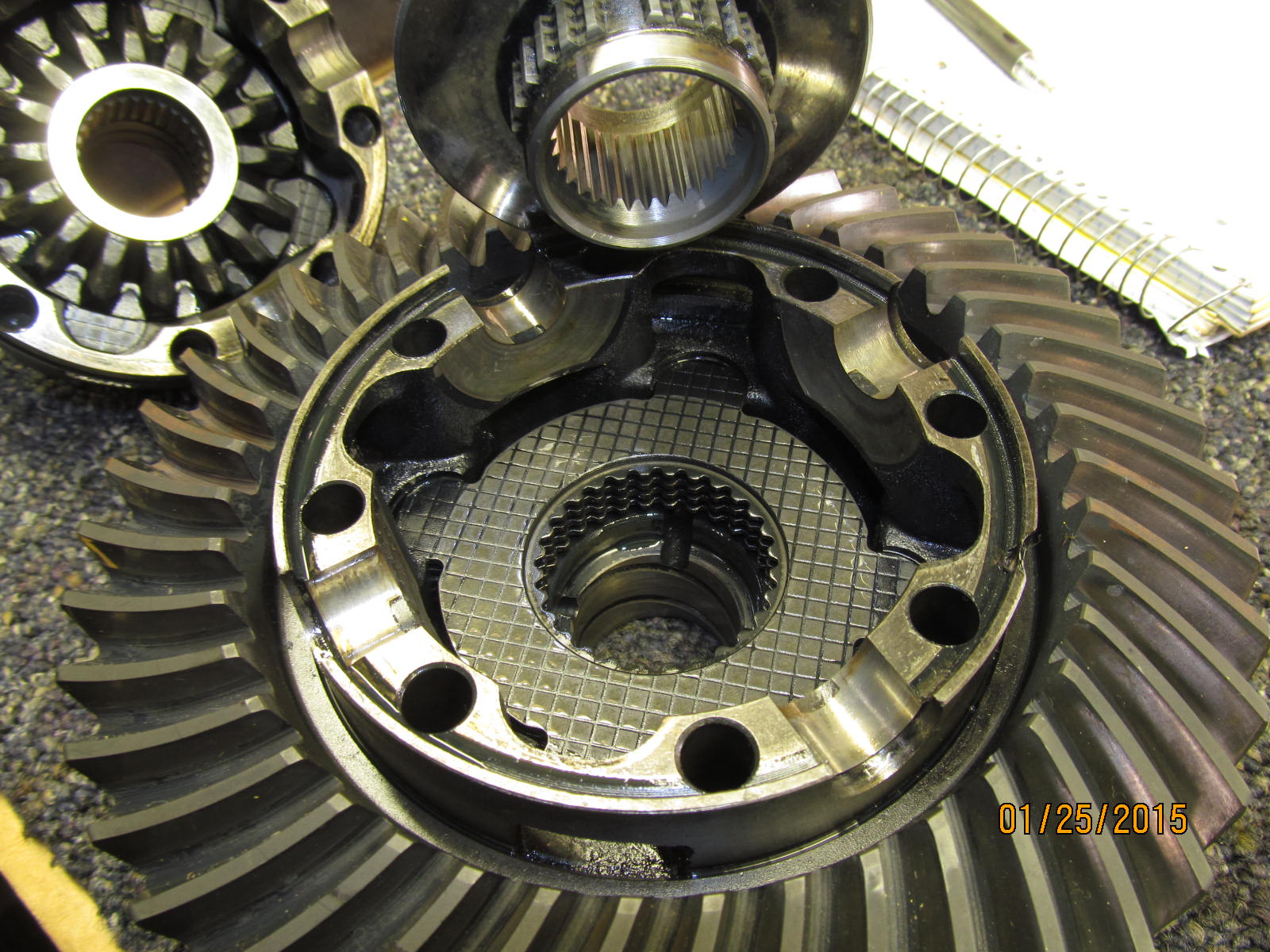
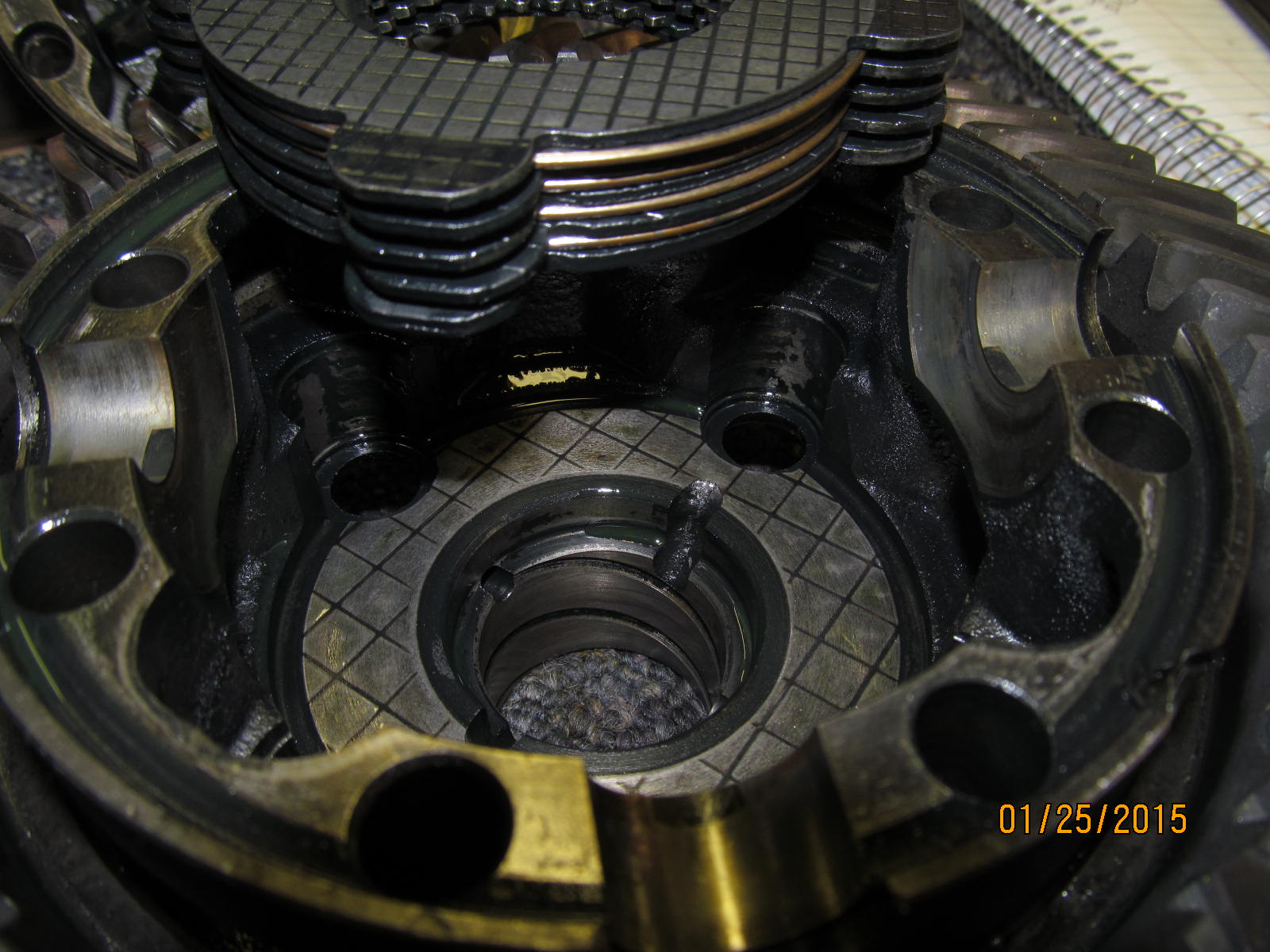
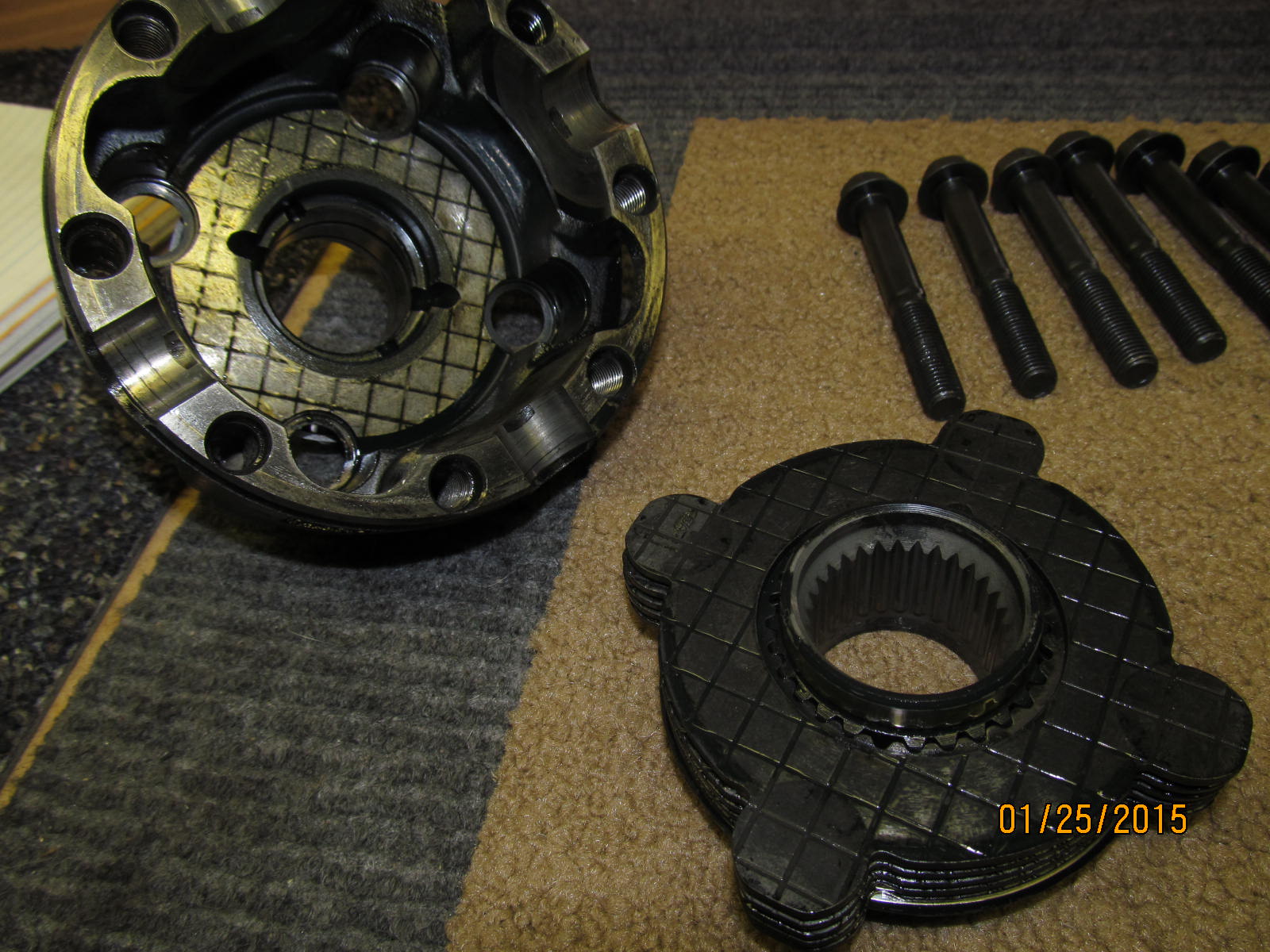
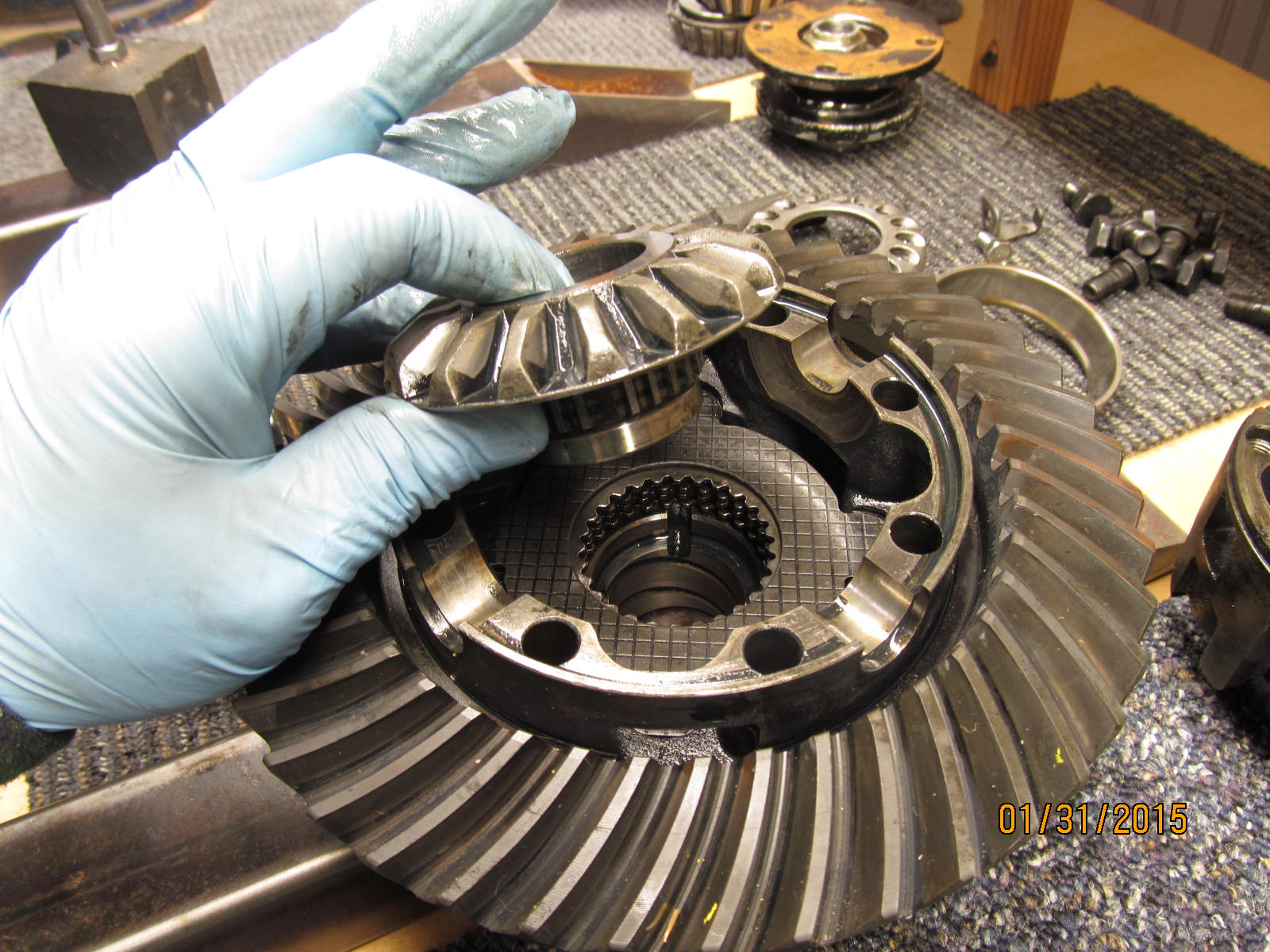
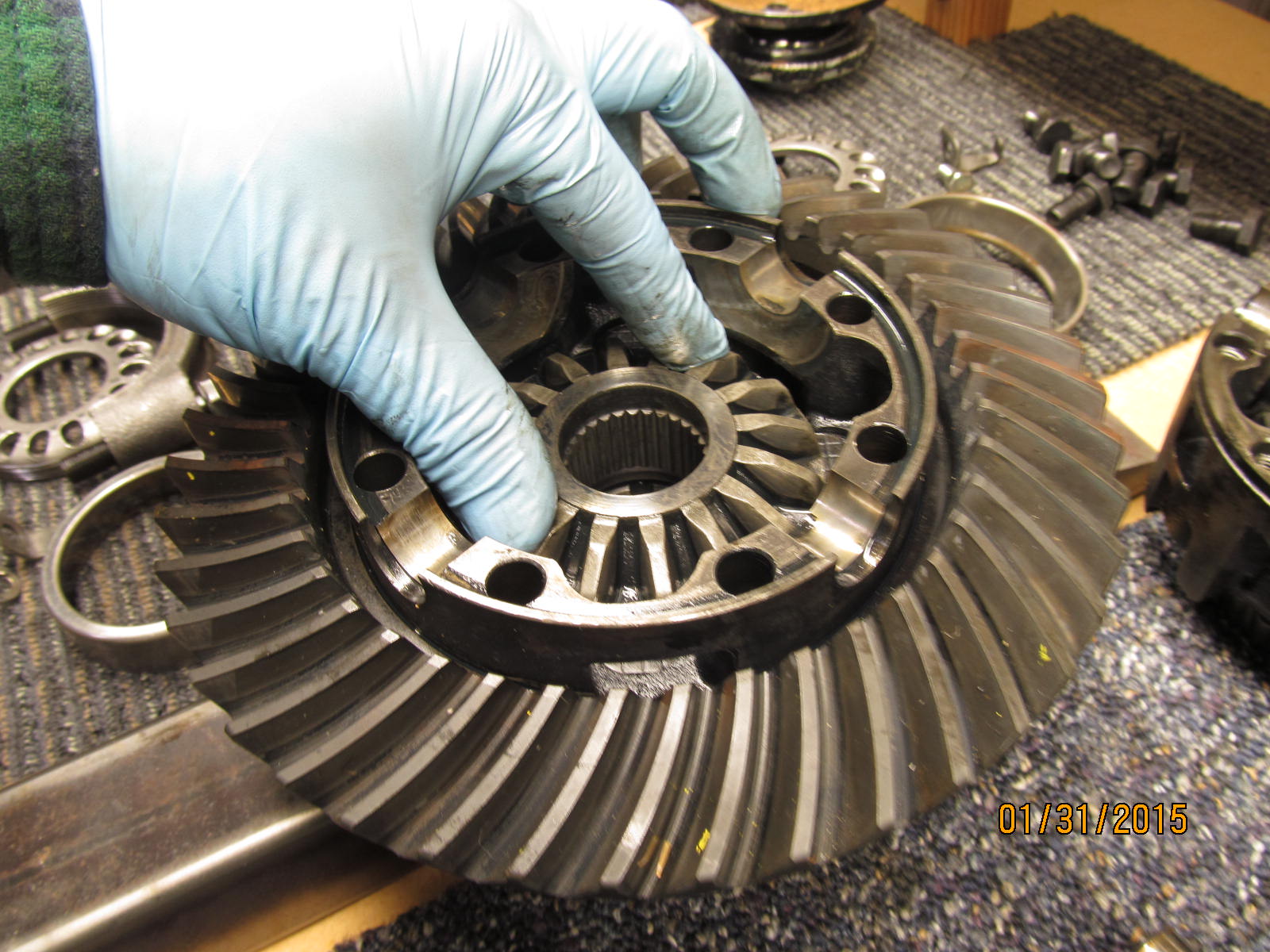
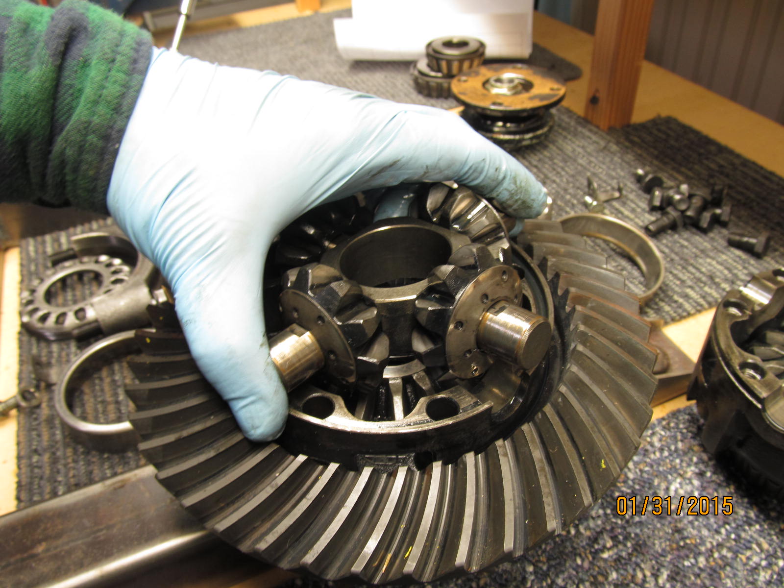
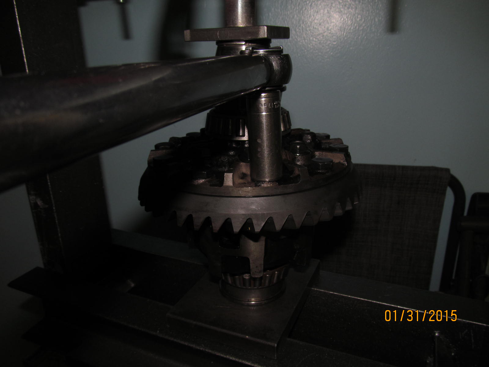
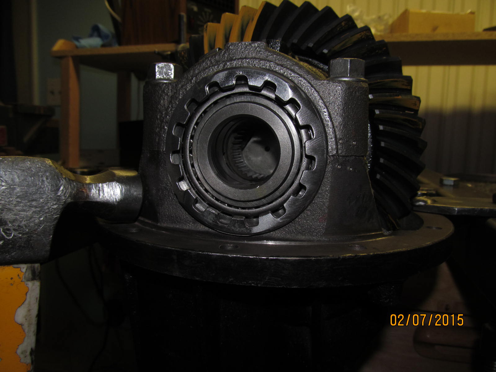
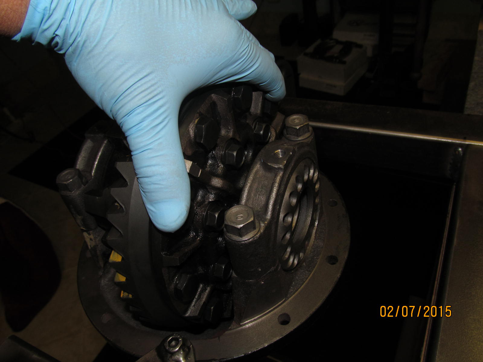
Remove the spider assembly...
|
|
|
|
|
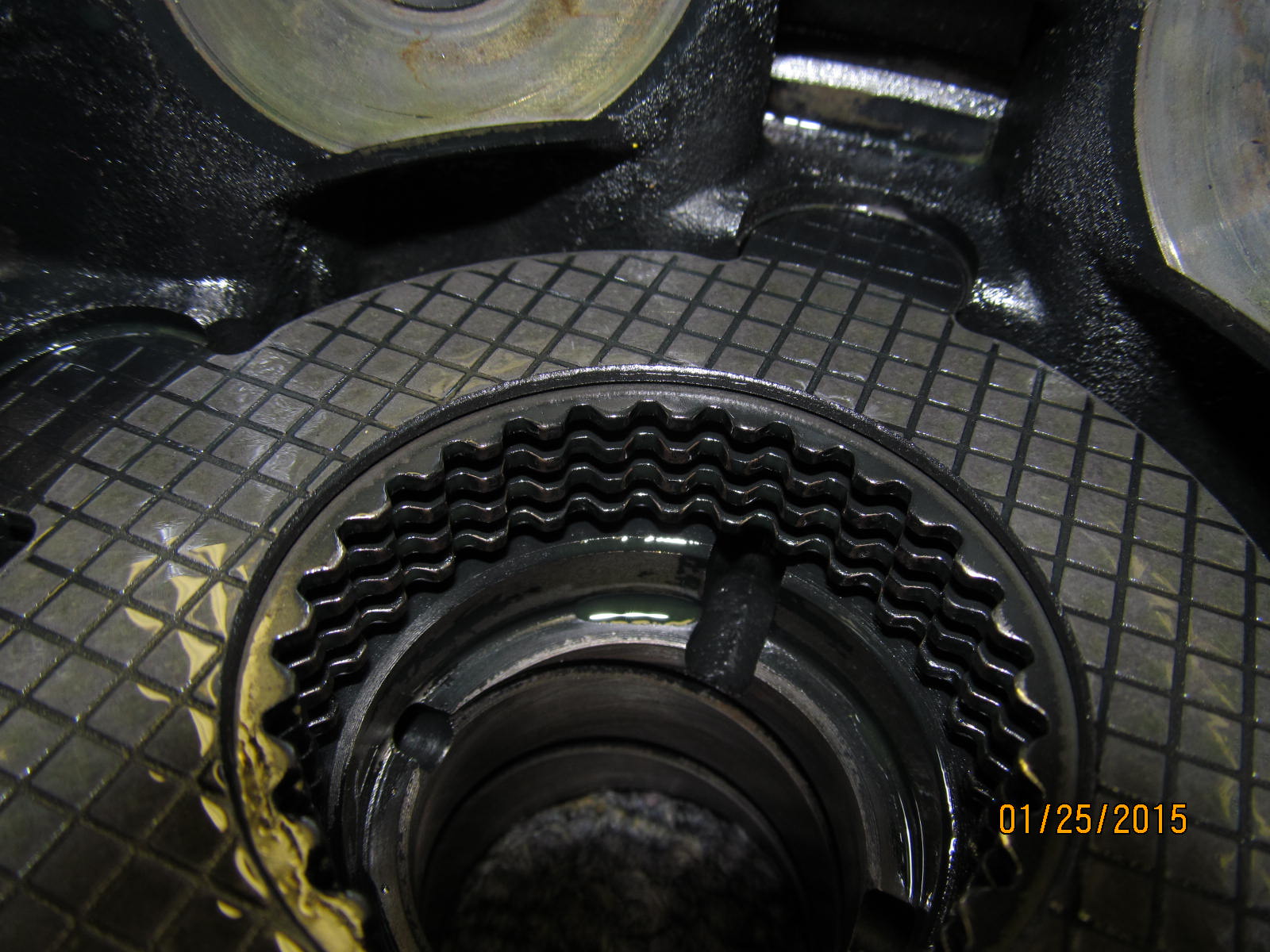
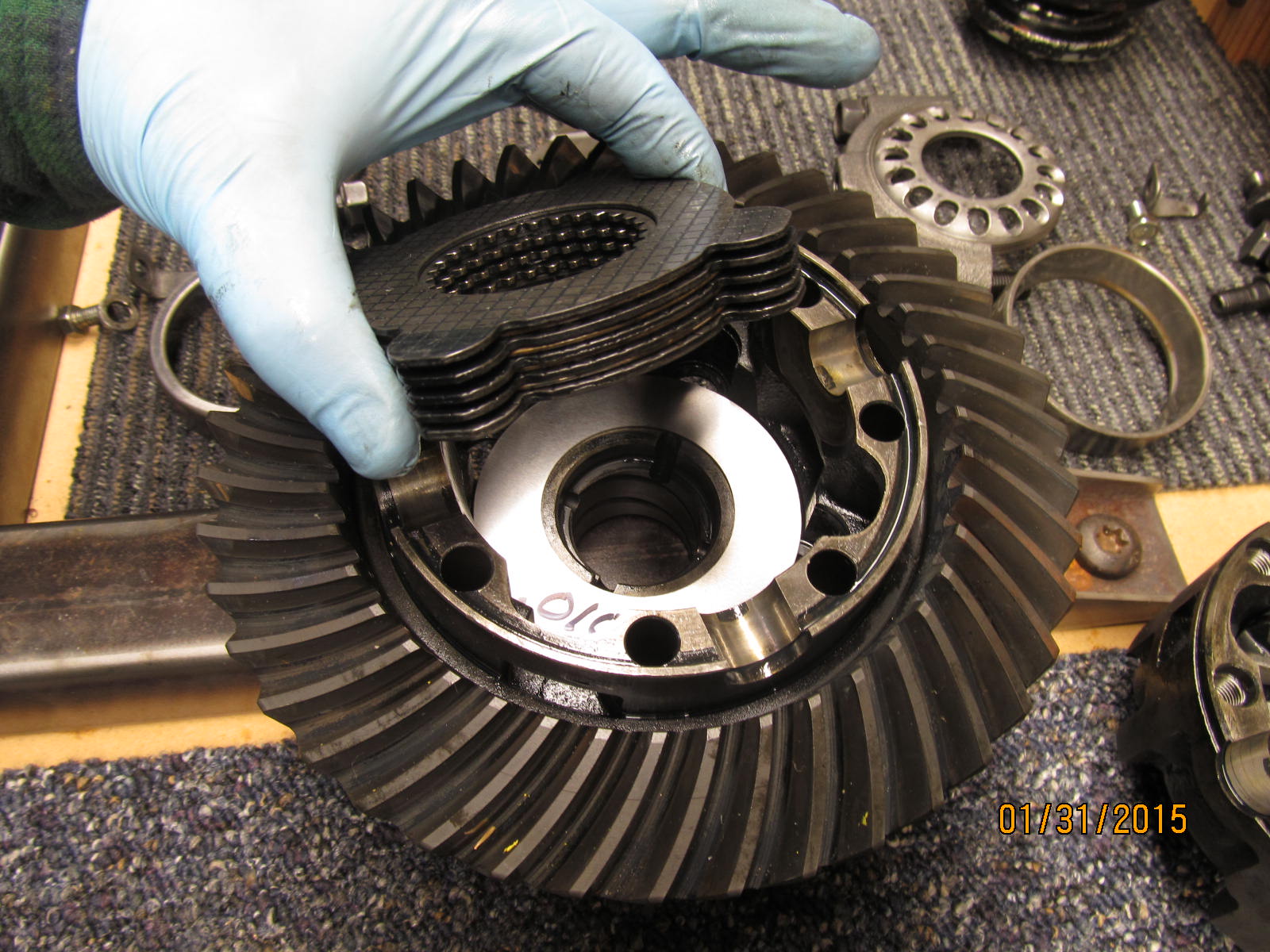
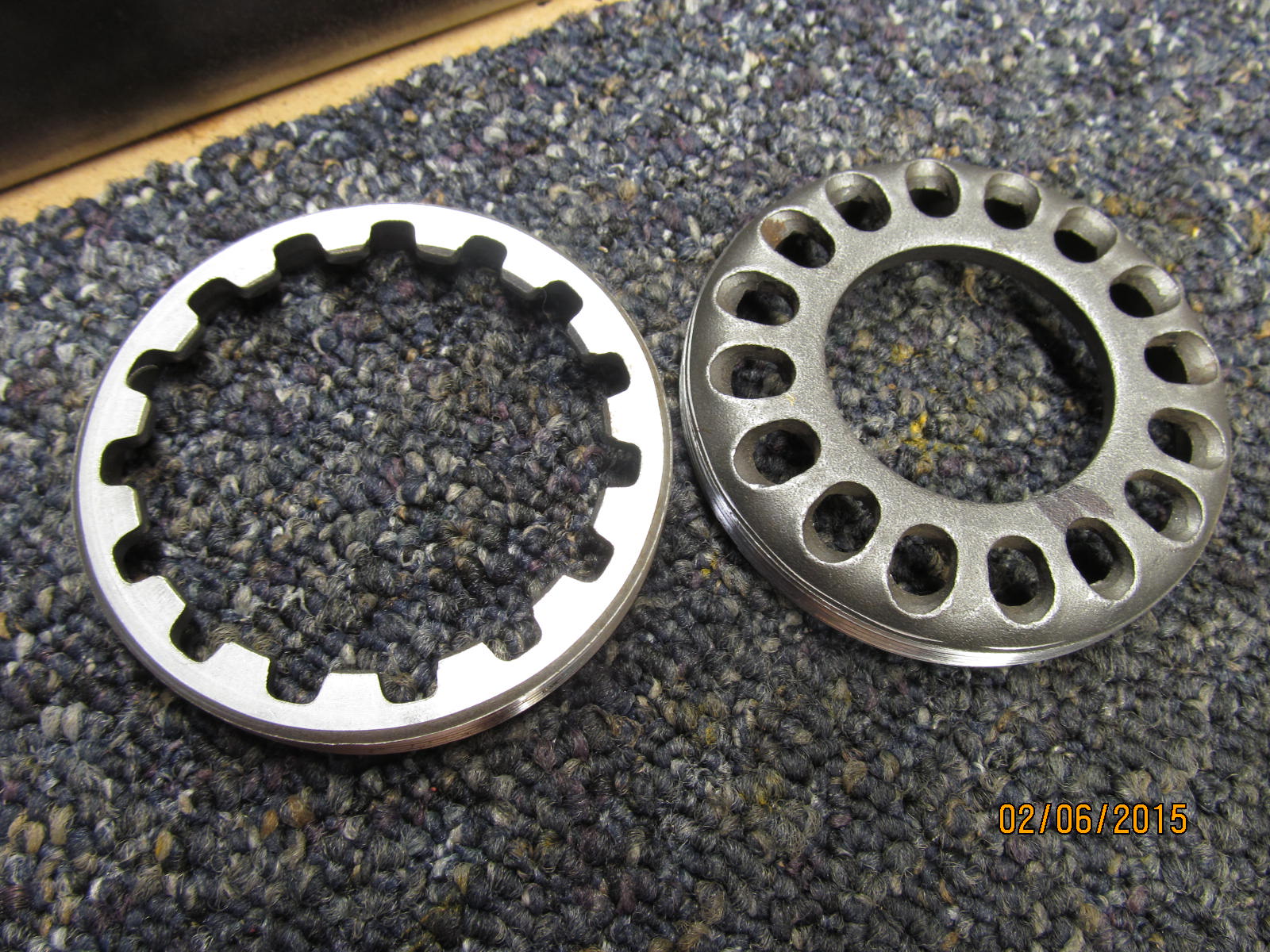
Behind the sidegears are the clutches.
|
|
|
|
|
......
|
|
|
|
|
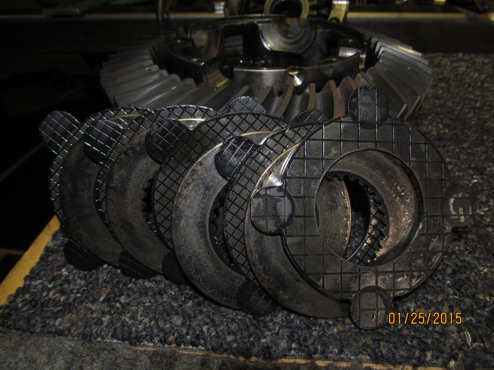
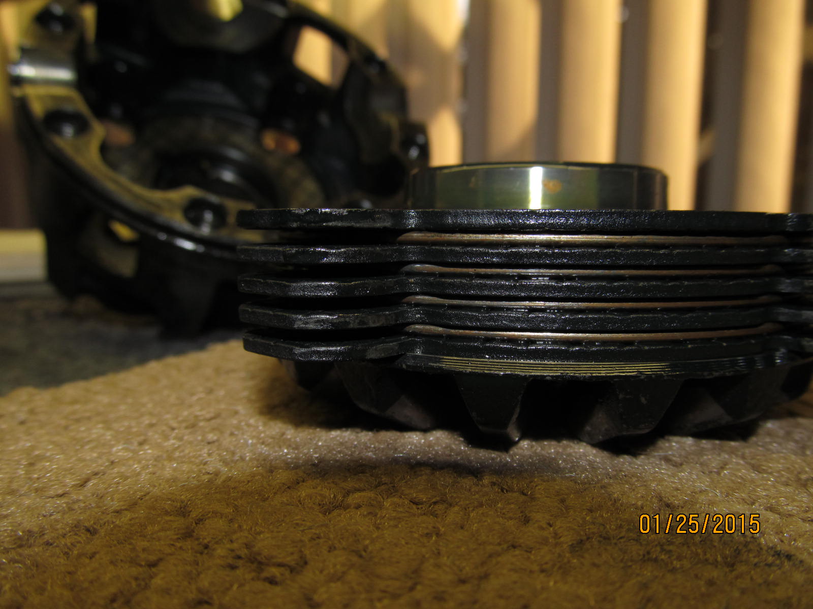
Notice the clutch plates alternate with spacers in between each of them.
|
|
|
|
|
.....
|
|
|
|
|
................
|
|
|
|
|
..............
|
|
|
|
|
..................
|
|
|
|
|
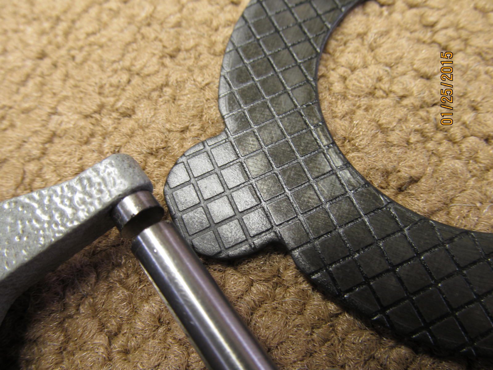
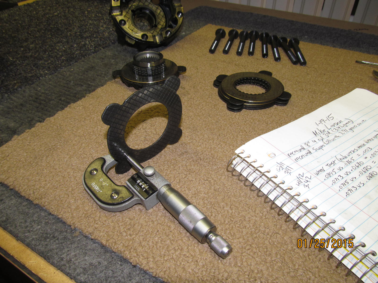
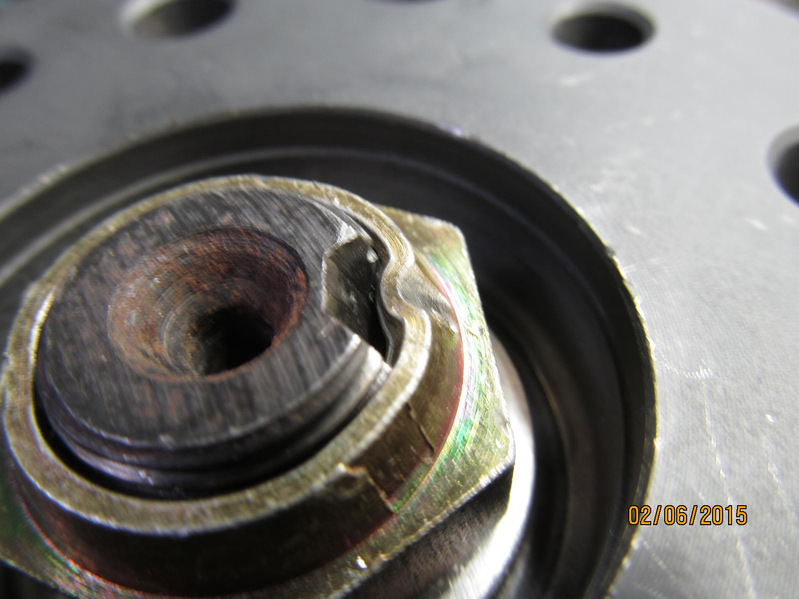
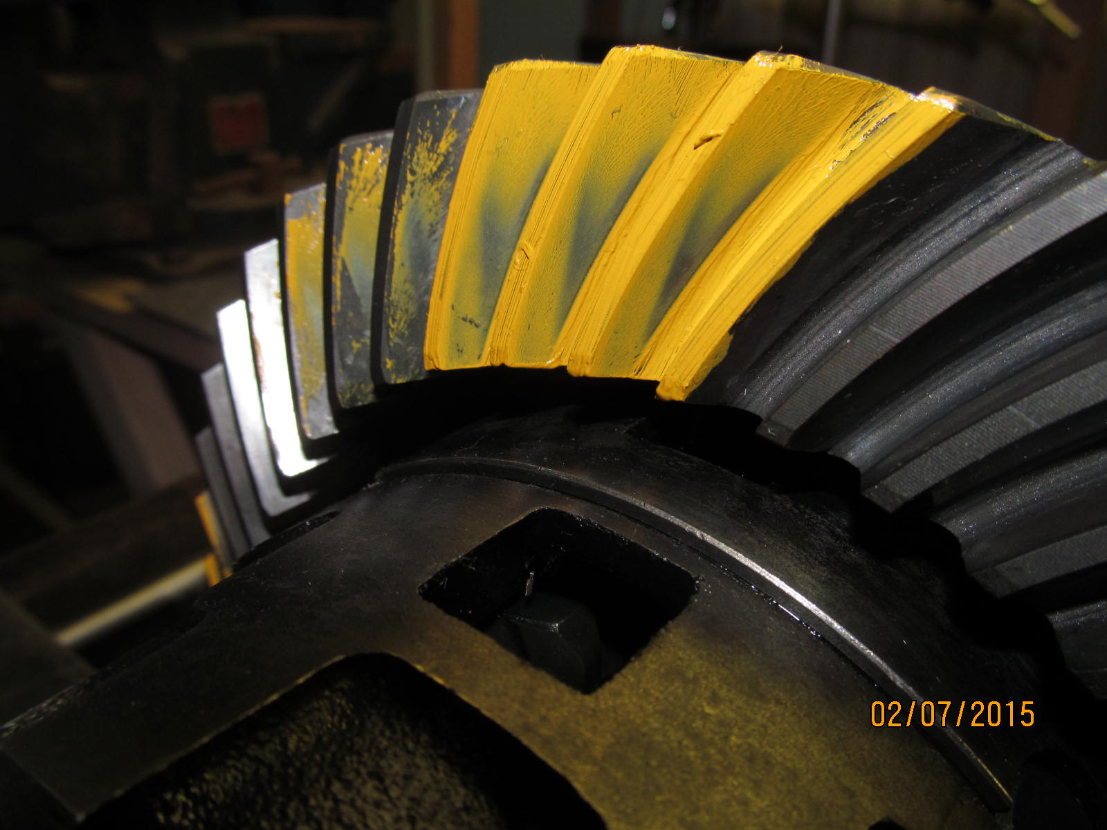
Comparing the wear in the active plane with the nubs on the end which basically have no contact and no wear.
|
|
|
|
|
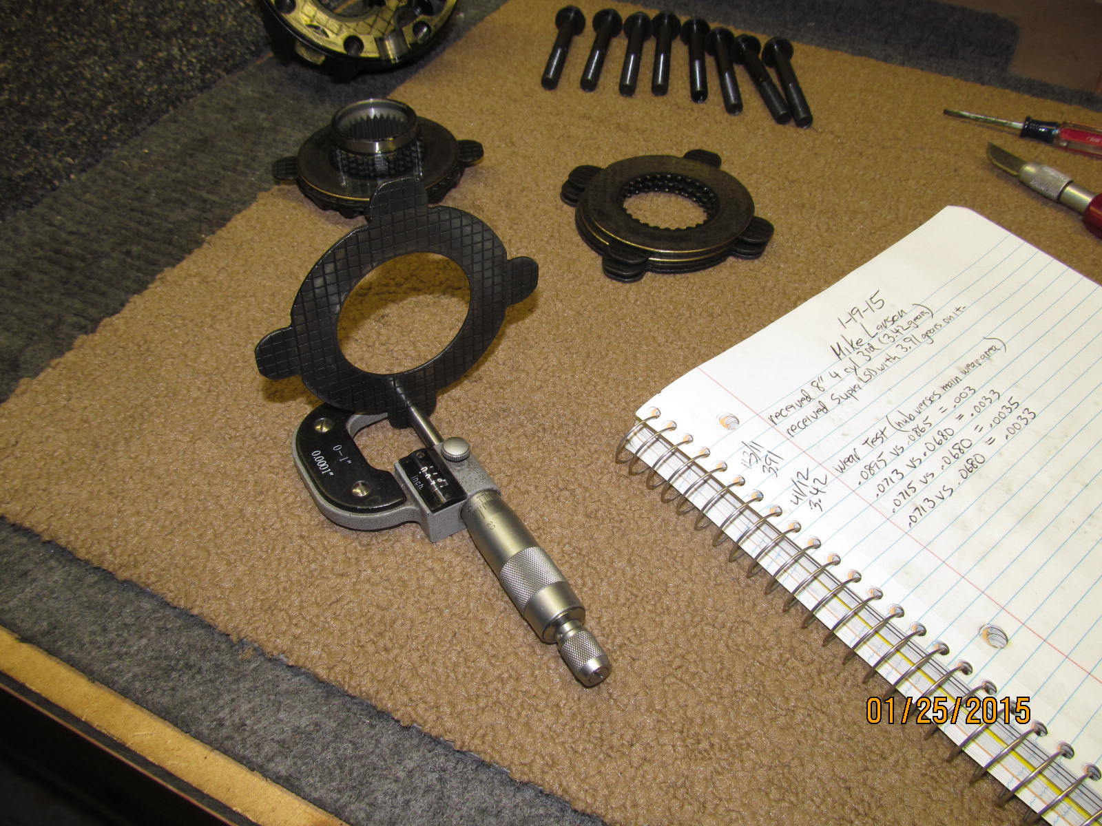
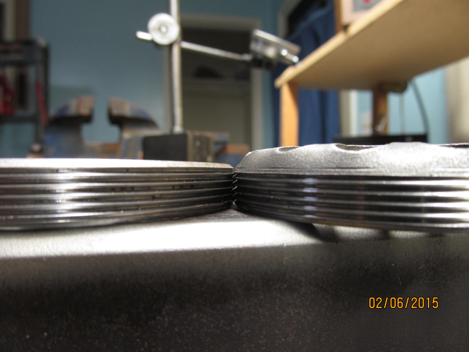
Measuring the "no wear area".....
|
|
|
|
|
.....and comparing it with the surface that does experience wear.
|
|
|
|
|
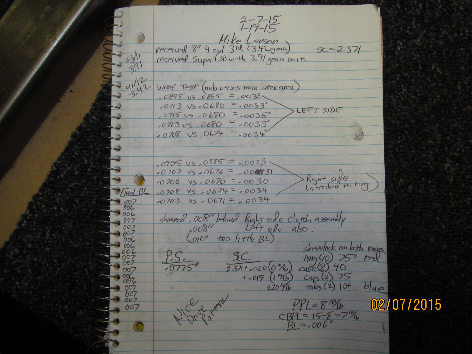
Less than .004" wear on each clutch plate....5 on each side and 10 total.
|
|
|
|
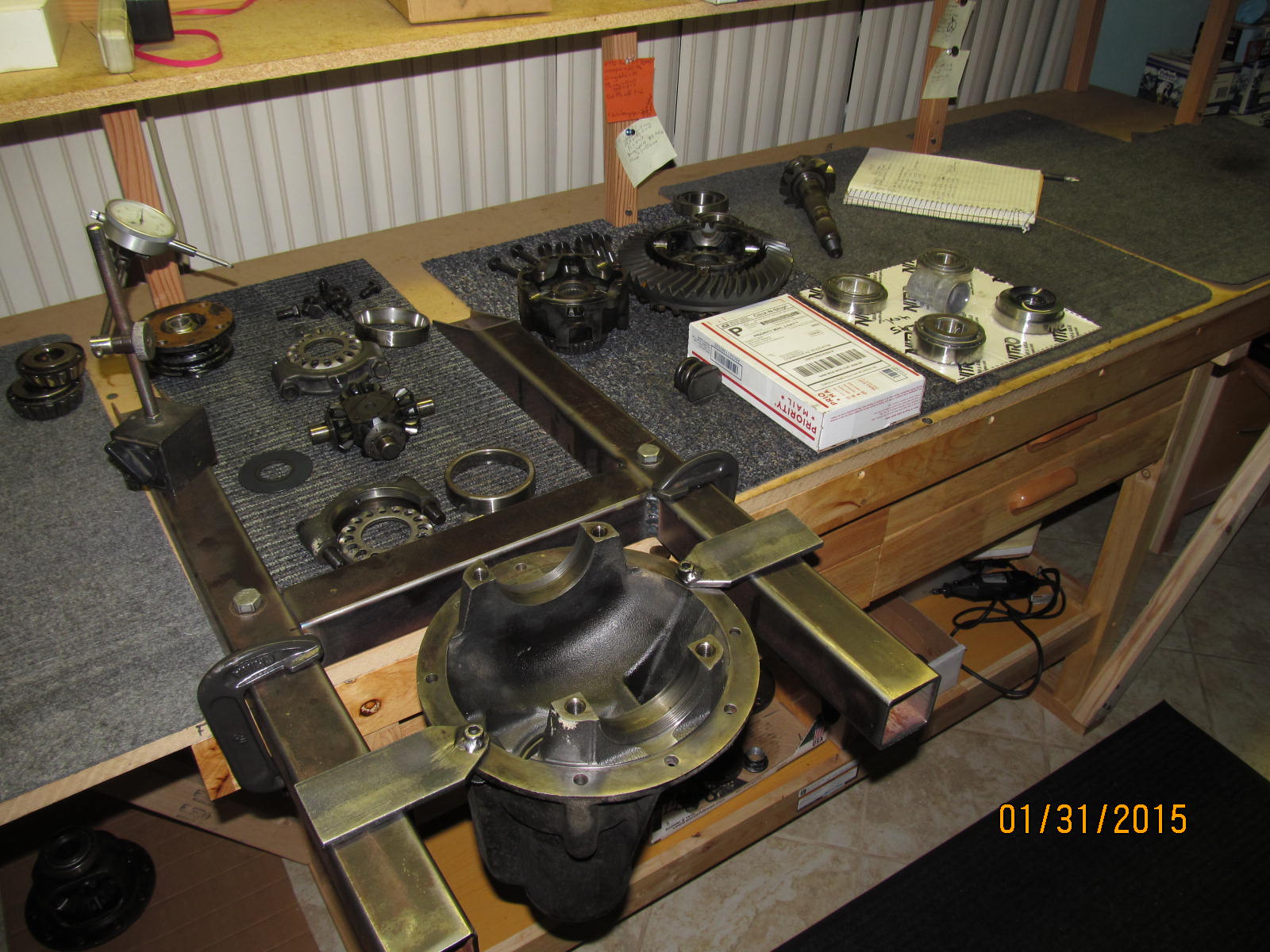
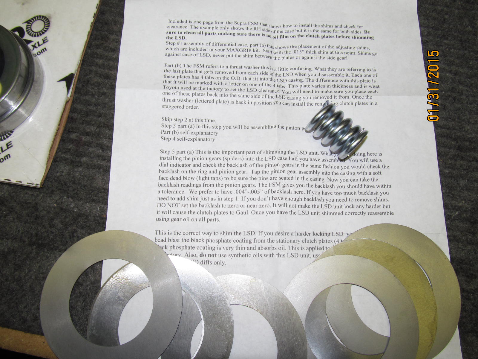
Received priority mail(USPS) is the maxgrip kit #1 from Weir Performance
Behind that is the Nitro bearing kit.
|
|
|
|
|
...................
|
|
|
|
|
........................
|
|
|
|
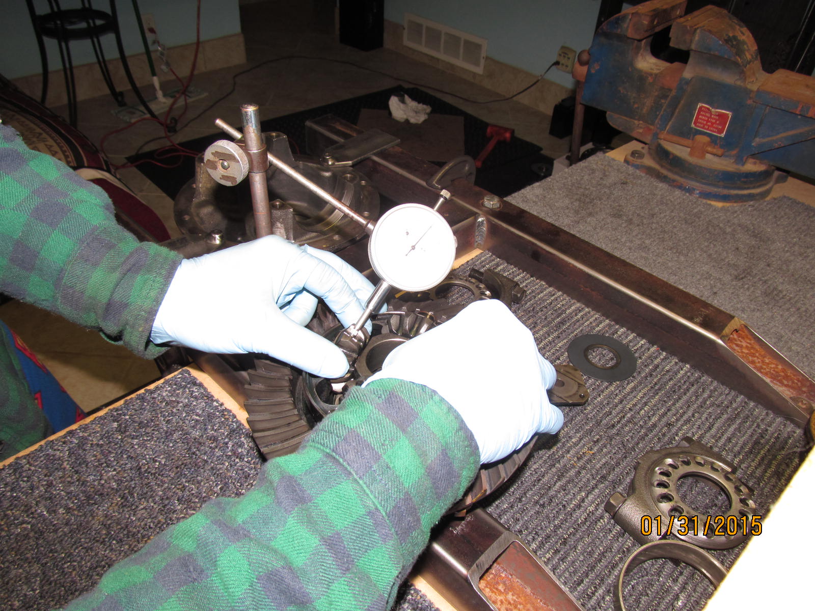
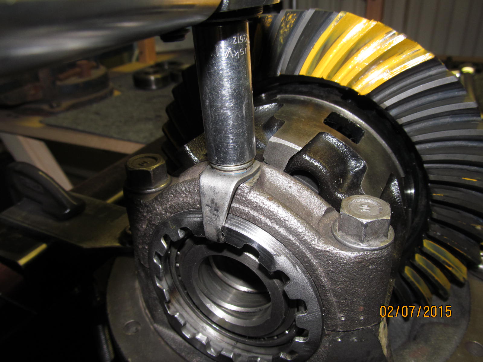
Checking sidegear to spider backlash. This can be tricky when the sidegear is moving around due to
250,000 miles of wear.
|
|
|
|
|
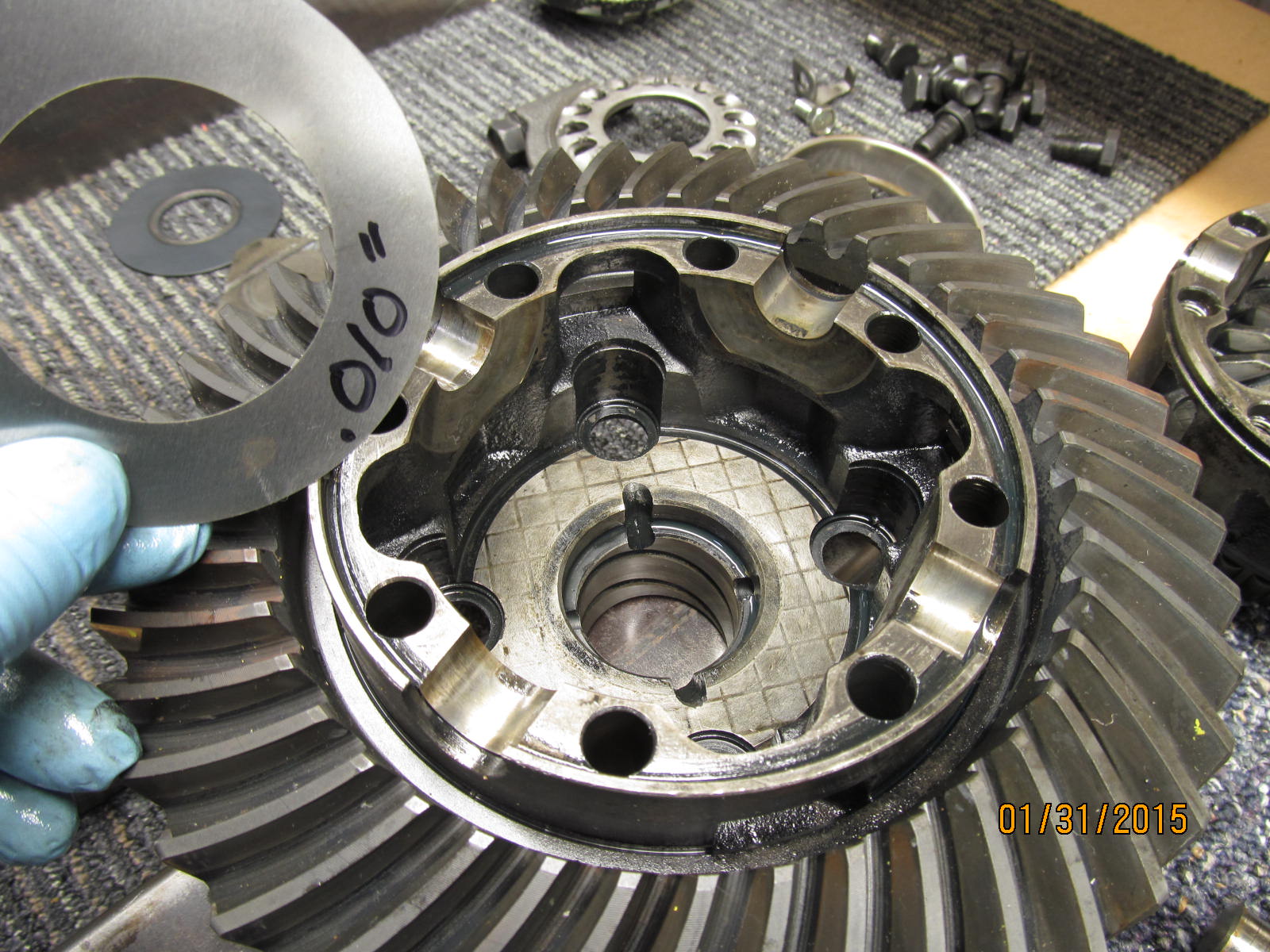
I tried .010" shim to tighten up the backlash and bring it into the middle of the recommended range.
|
|
|
|
I partially assembled it and found that the BL was a bit too tight so, in the end,
the thinner .008" shims did the trick.
|
|
|
|
|
.............
|
|
|
|
|
..................
|
|
|
|
|
...................
|
|
|
|
|
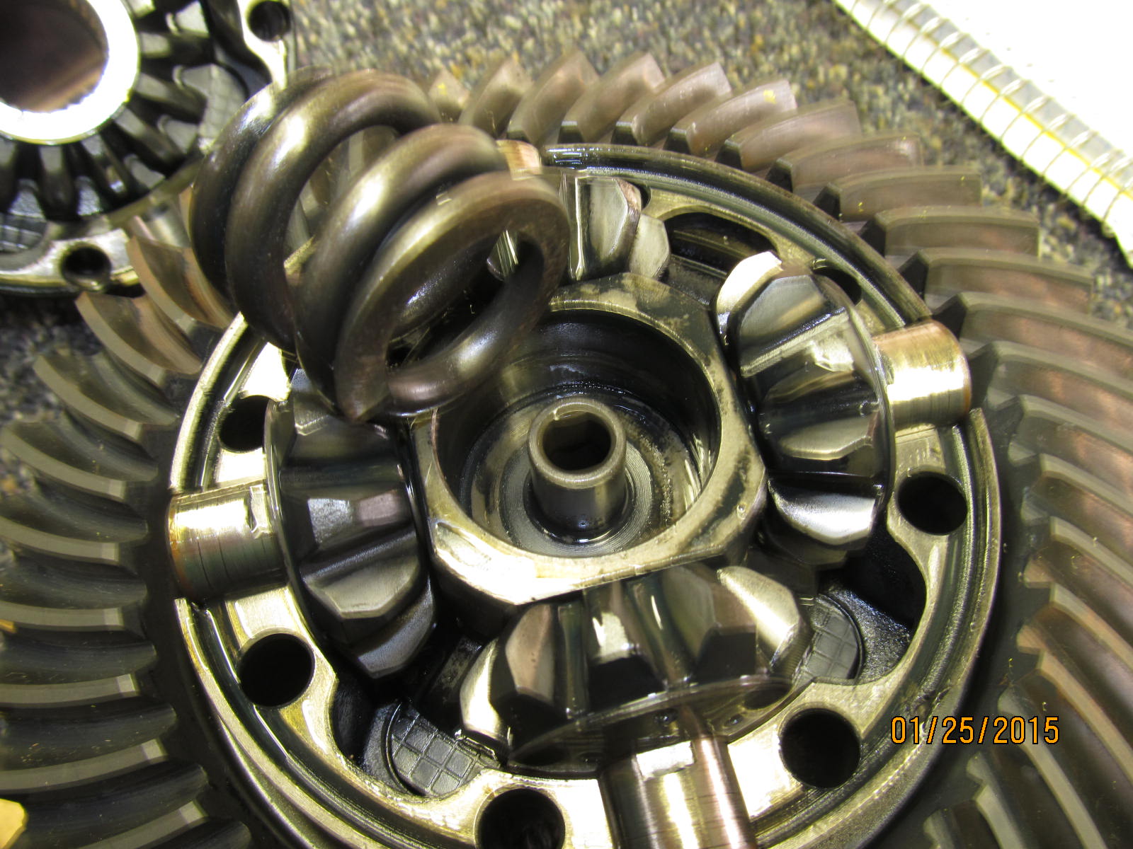
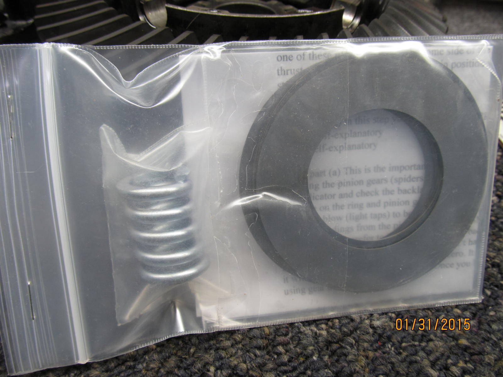
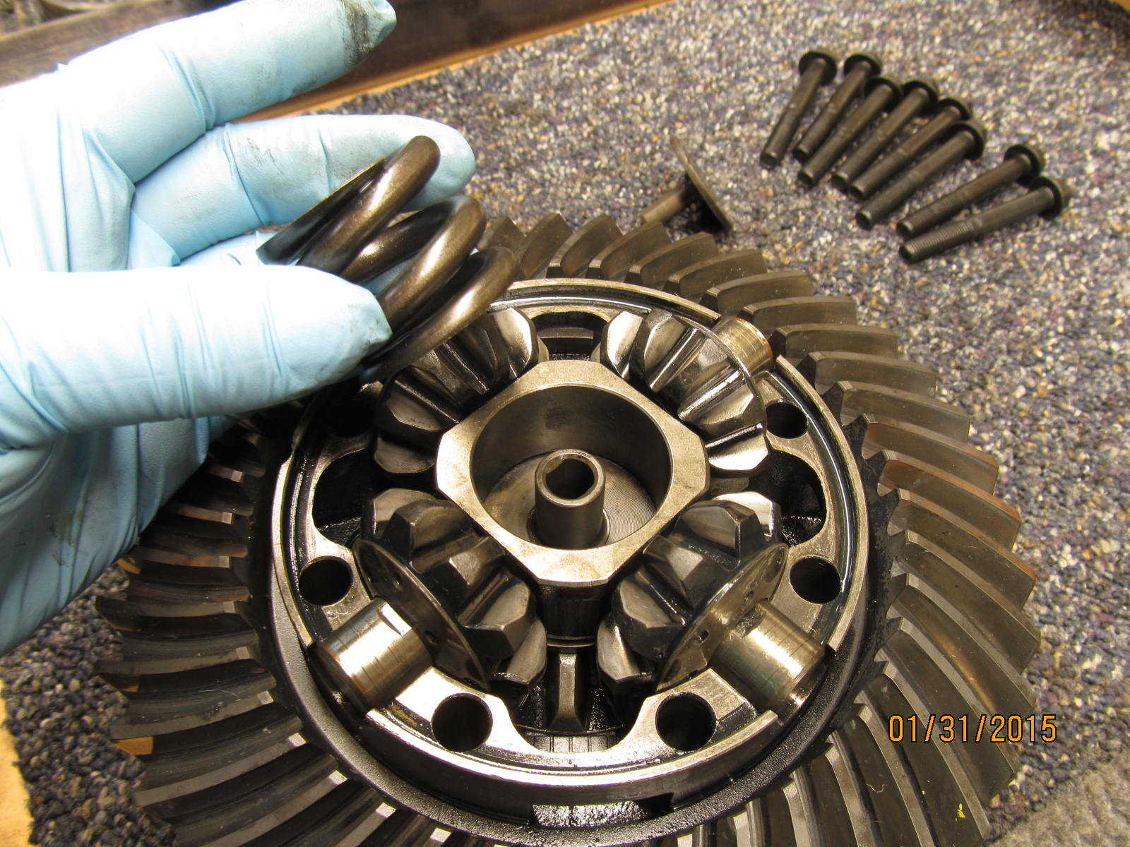
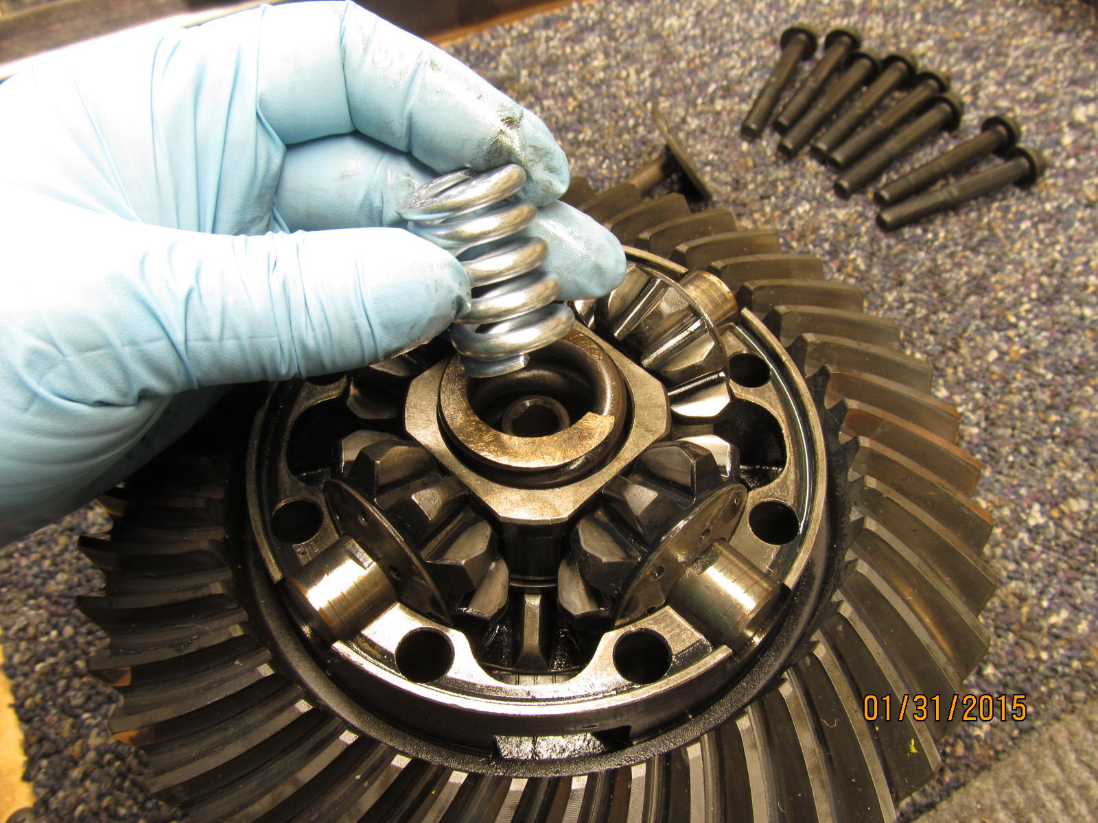
Original main spring is re-installed.
|
|
|
|
Add in the stout auxilary spring inside the larger main one. Don't let the skinny appearance make you think this
spring is wimpy.....it's very stiff and does not compress easily.
|
|
|
|
|
...................
|
|
|
|
|
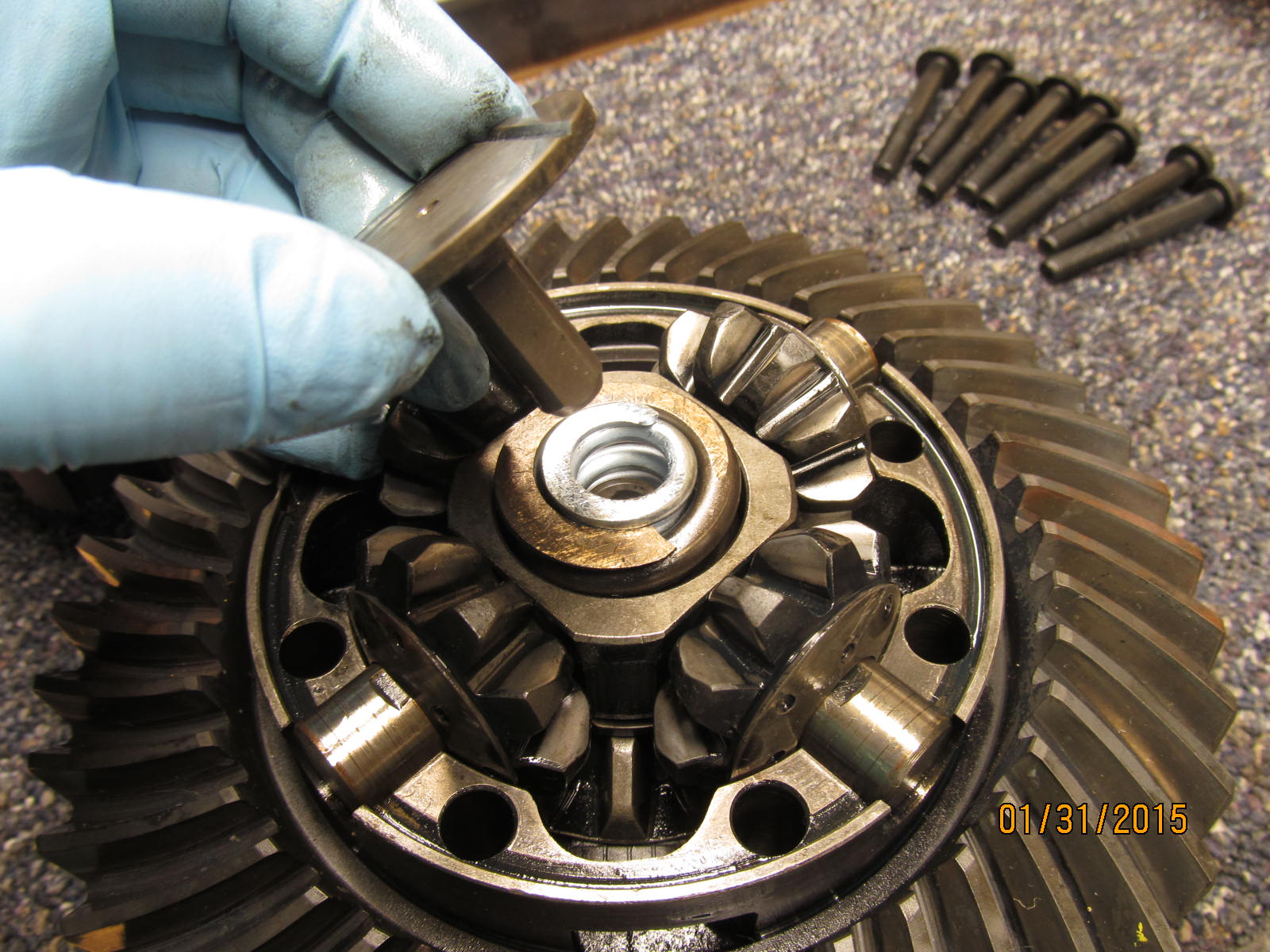
It's a snug fit and some light taps from a hammer will make it go easy.
|
|
|
|
|
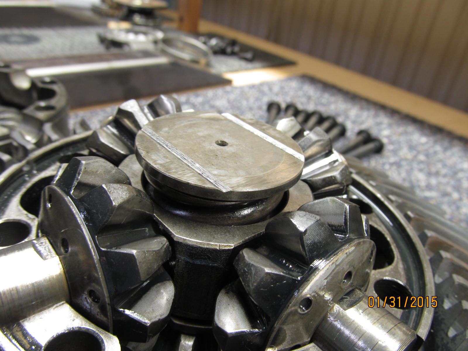
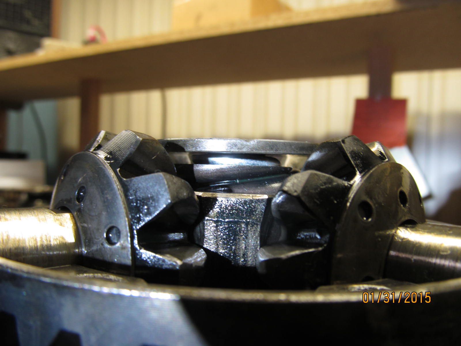
Fully seated.
|
|
|
|
|
The case has drilled spot to put the case back together exactly in the same orientation.
|
|
|
|
|
...........
|
|
|
|
|
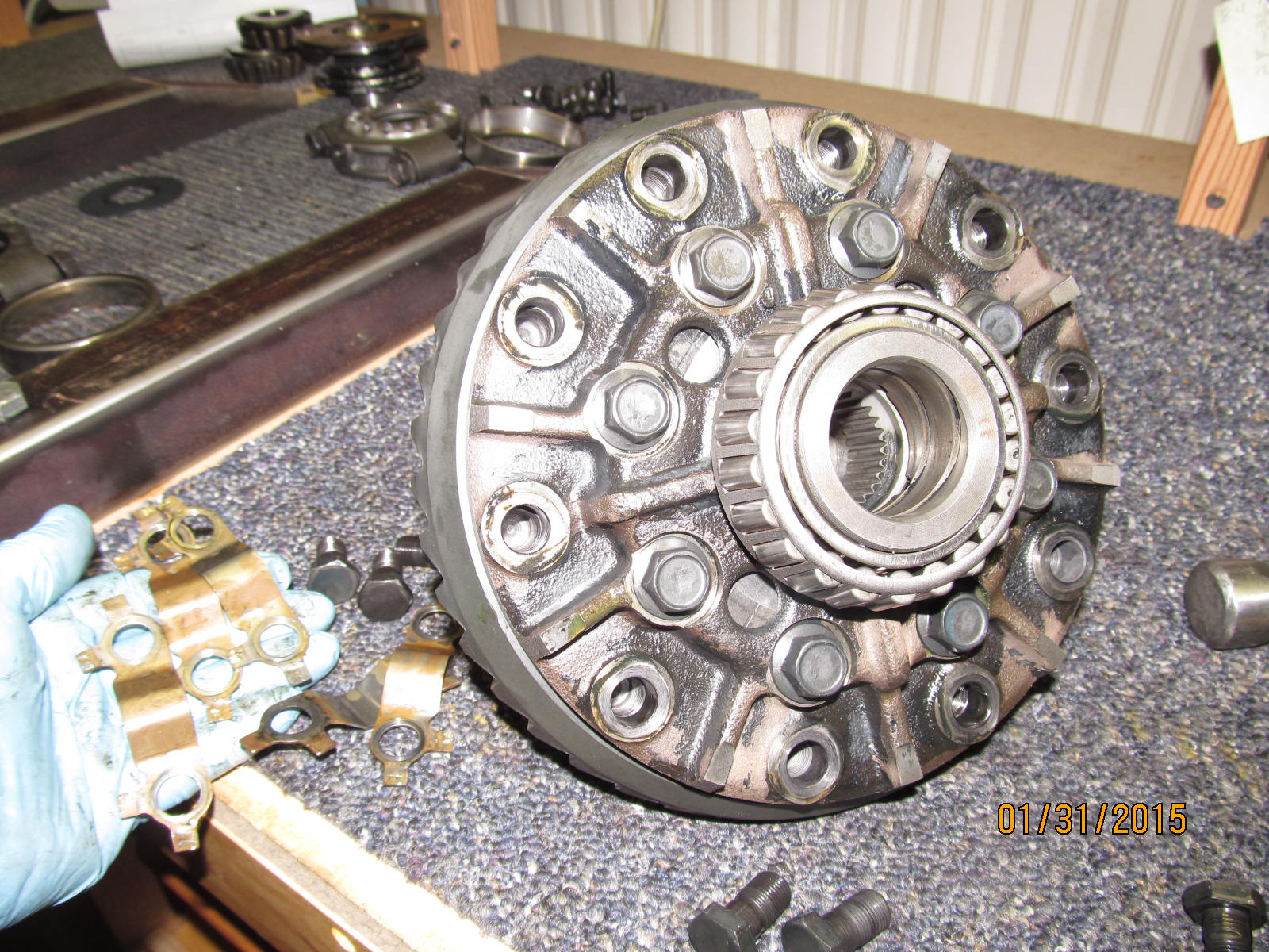
At this point, I just snugged up the 8 case bolts and removed those nasty Toyota ring gear safety tabs.
|
|
|
|
|
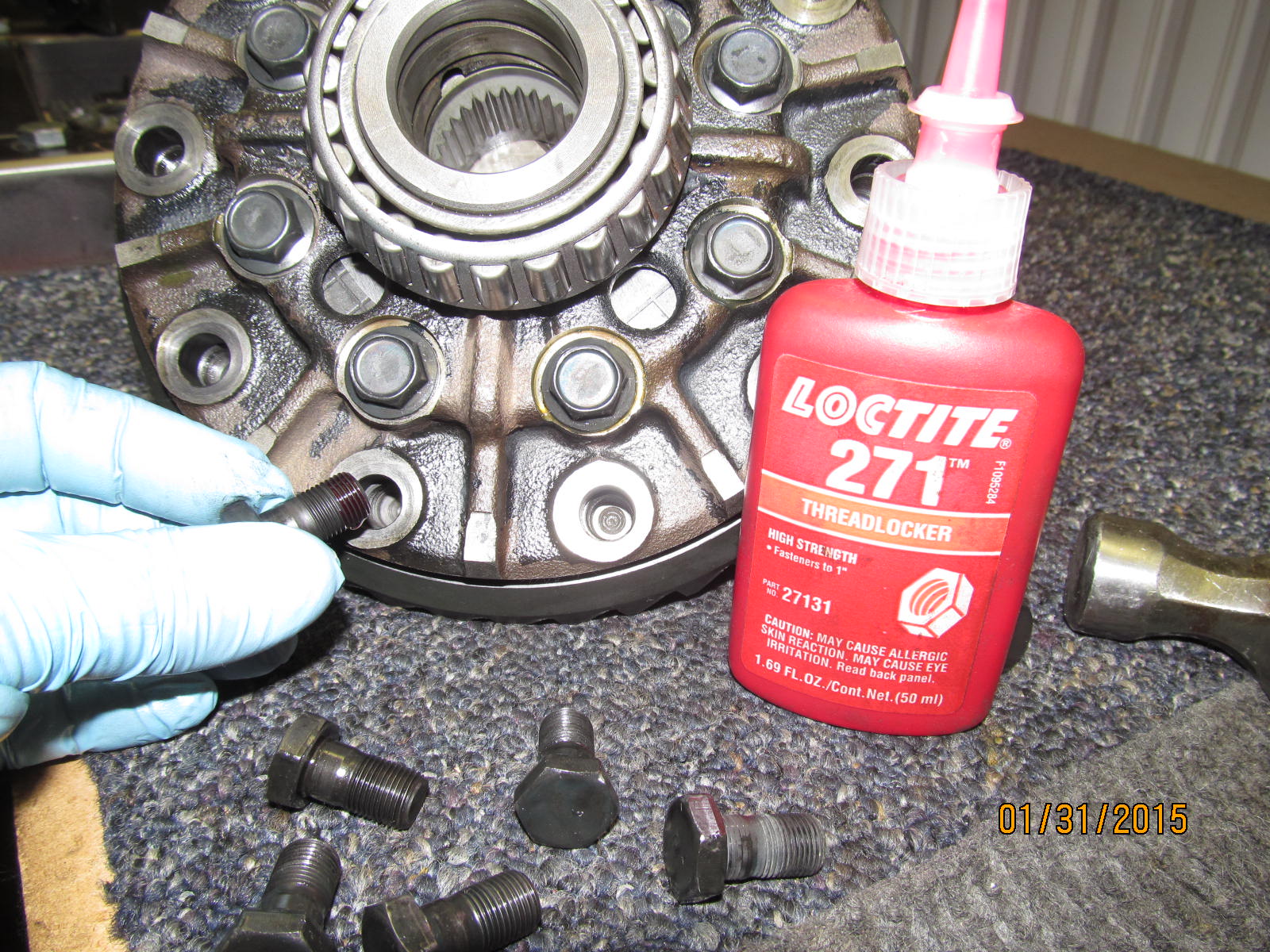
High strength red loctite #271 is applied to clean threads.
|
|
|
|
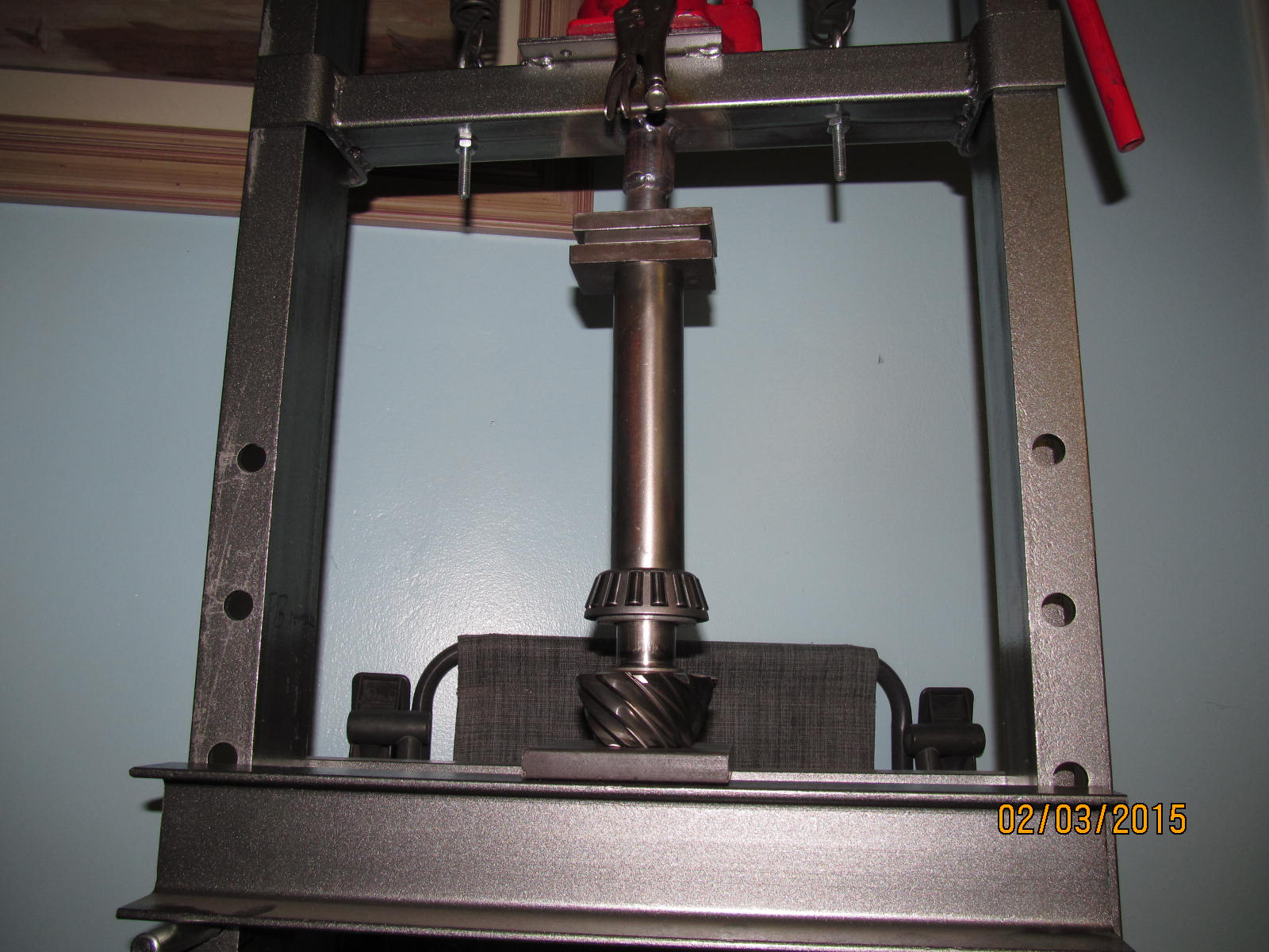
It's convenient to put the case in the press and then tighten the 8 case bolts to 40 ft/lbs. There should not be any
loctite on these bolts....just a light coating of gear oil suffices.
|
|
|
|
|
Then tighten the 10 ring gear bolts to 75 ft/lbs.
|
|
|
|
|
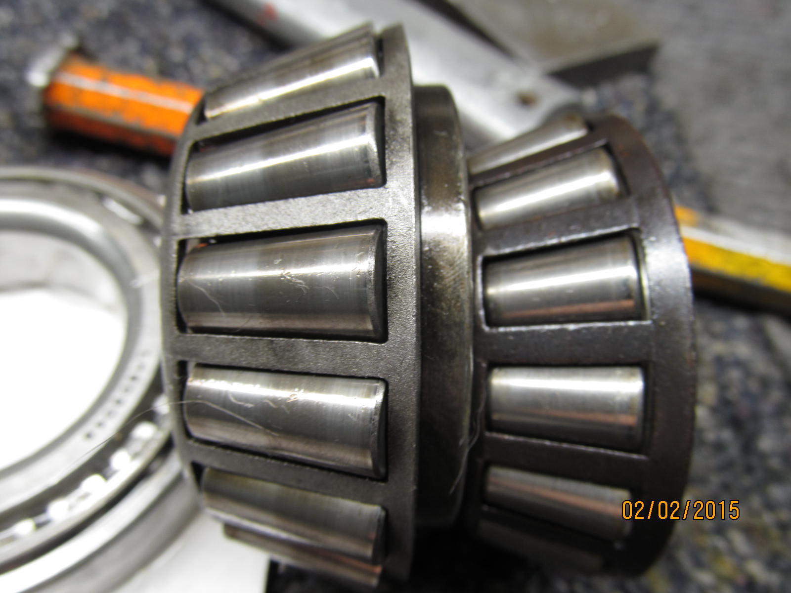
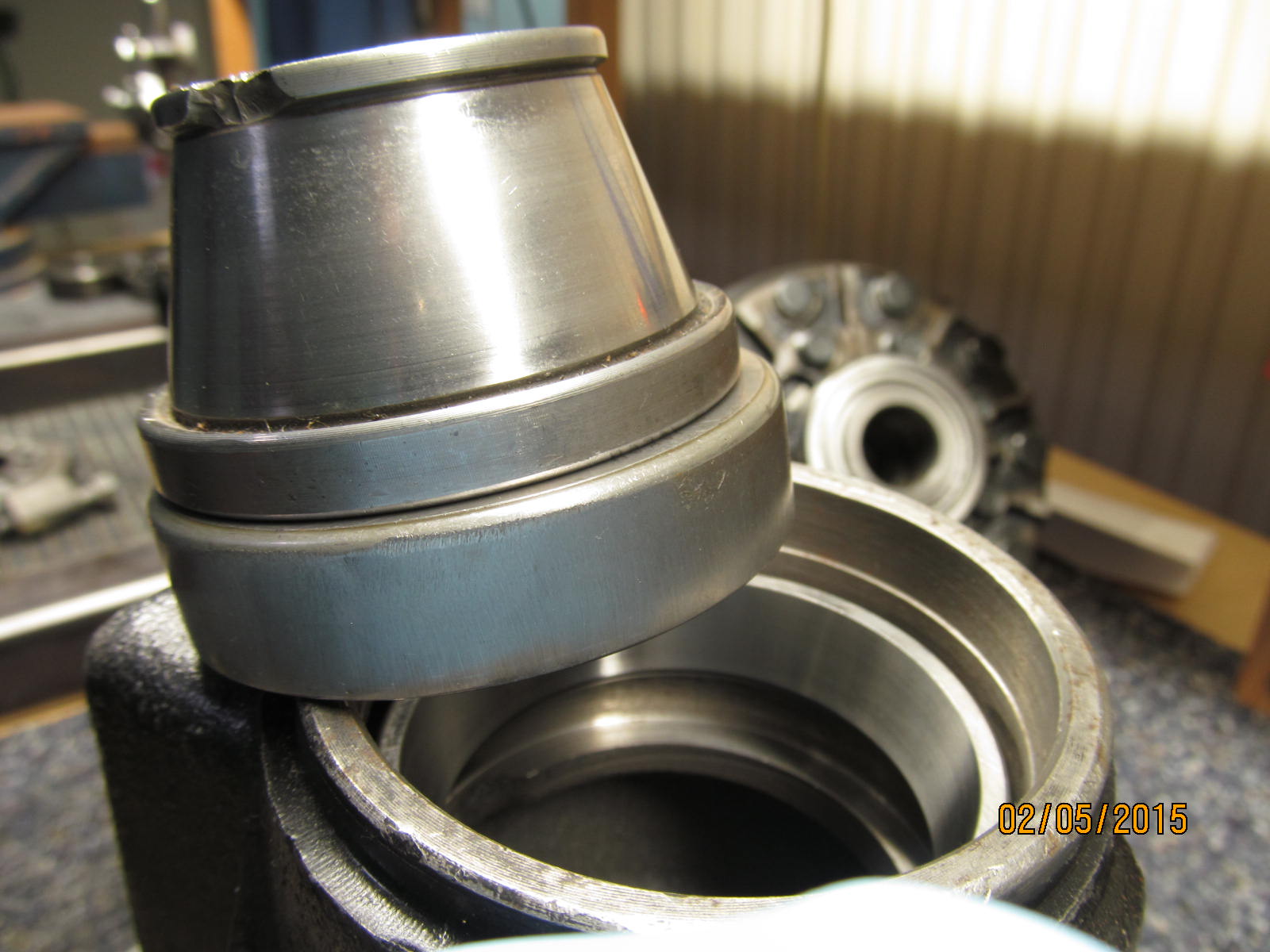
These are the old used pinion bearings.
|
|
|
|
|
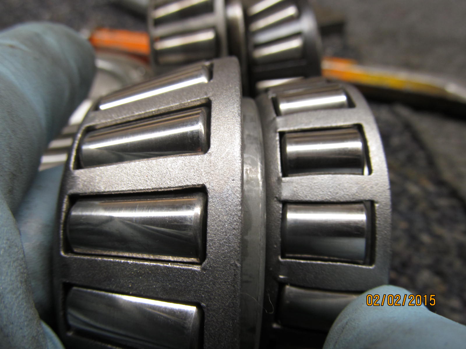
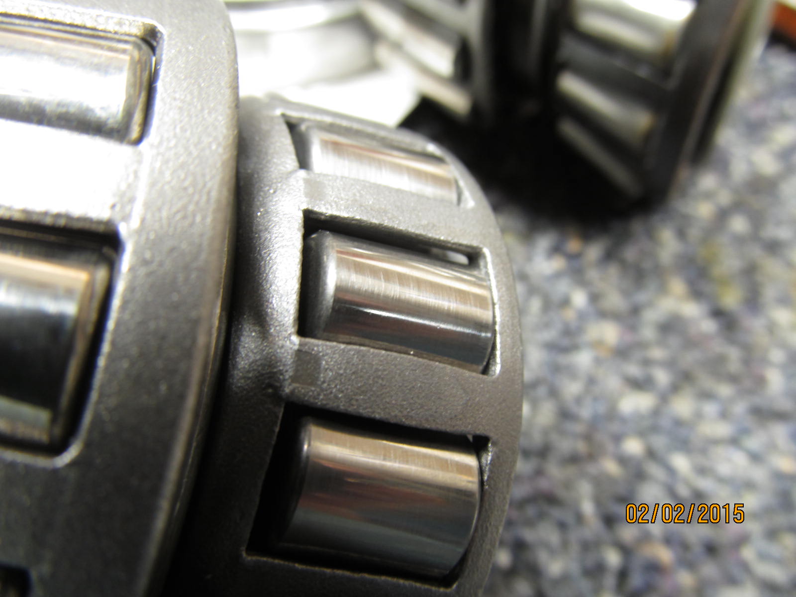
These are the new pinion bearings.
|
|
|
|
The photos don't do them justice but the rollers are very close to appearing like as if they were buffed out.
I think they do that for lower noise levels.
|
|
|
|
|
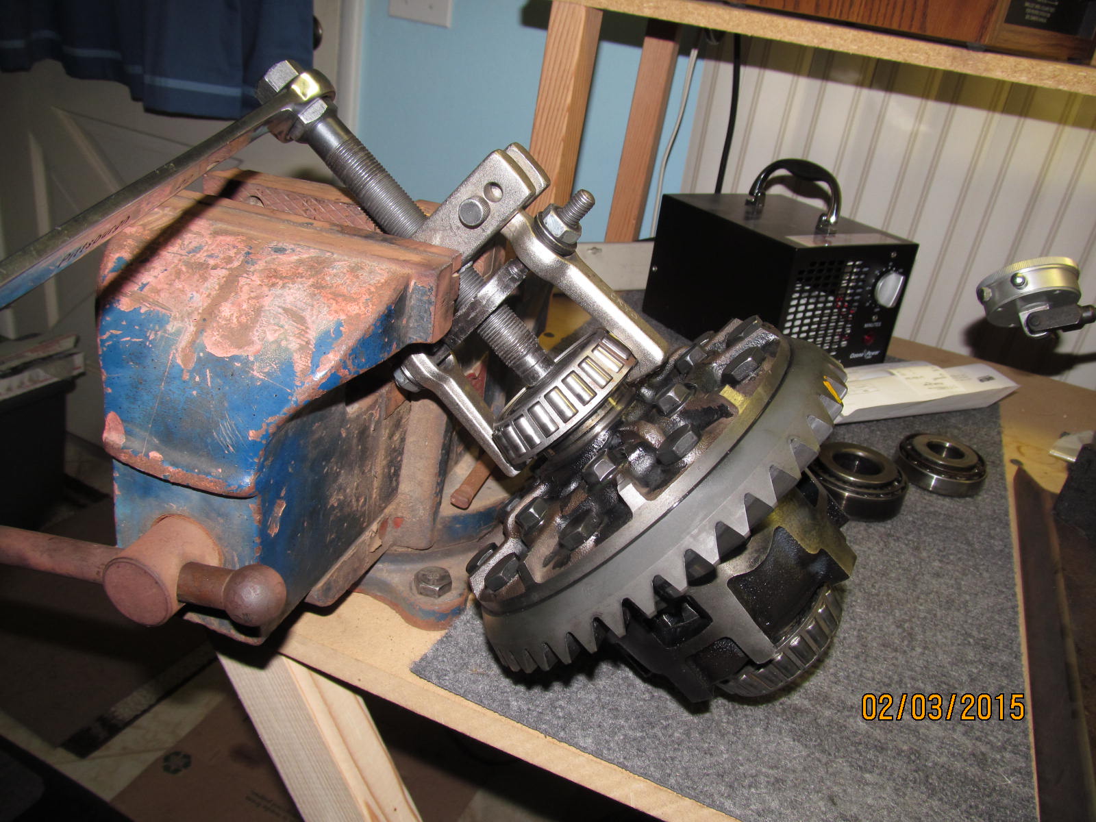
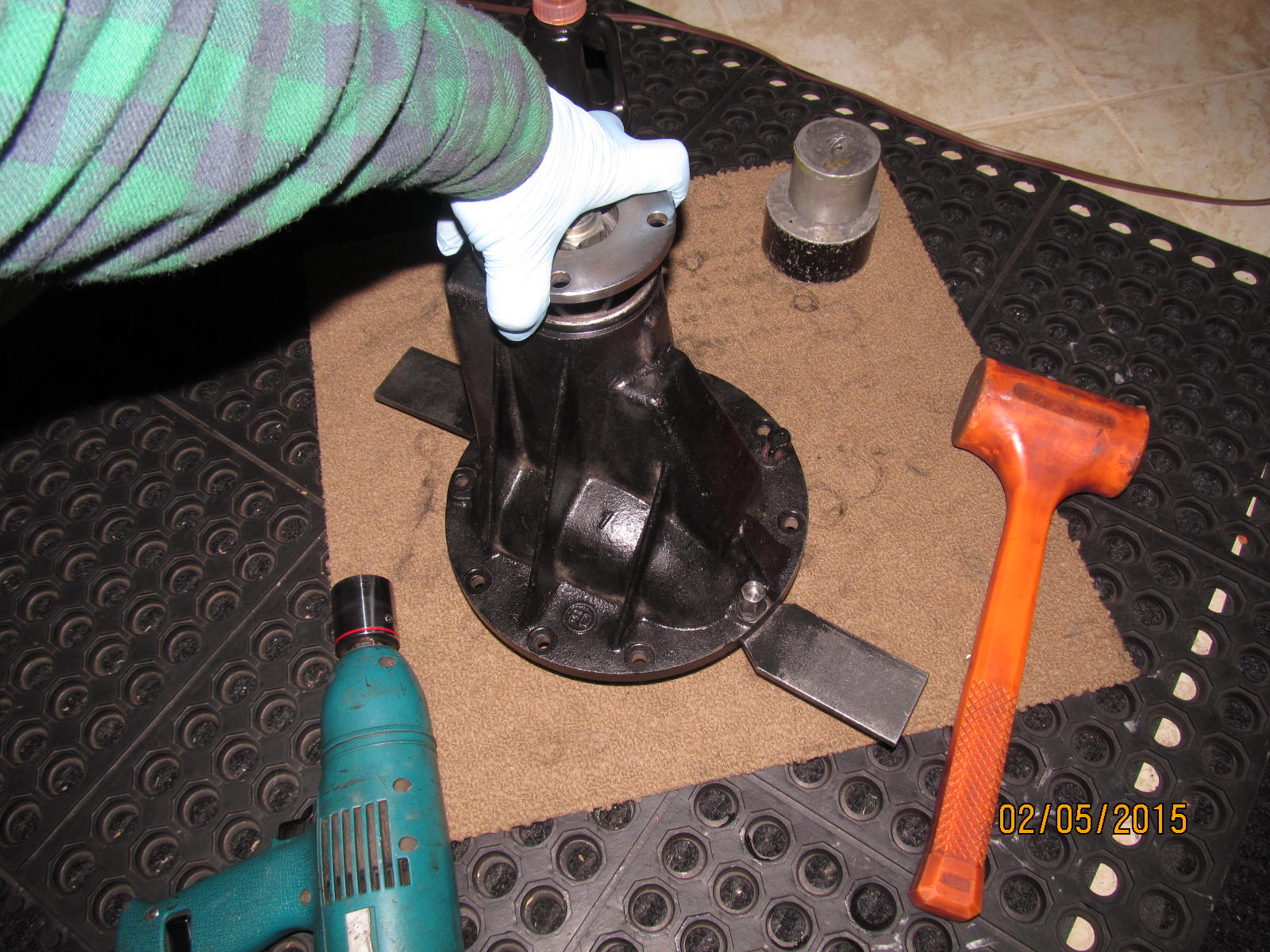
Old carrier bearings are removed with the OTC-4520.
|
|
|
|
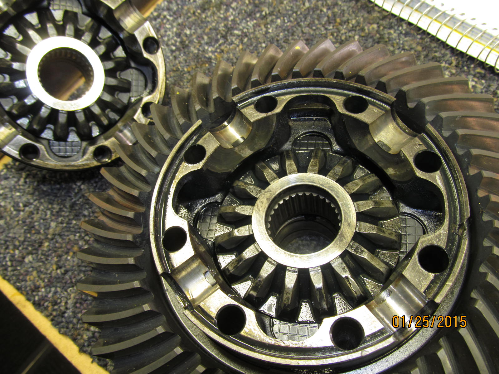
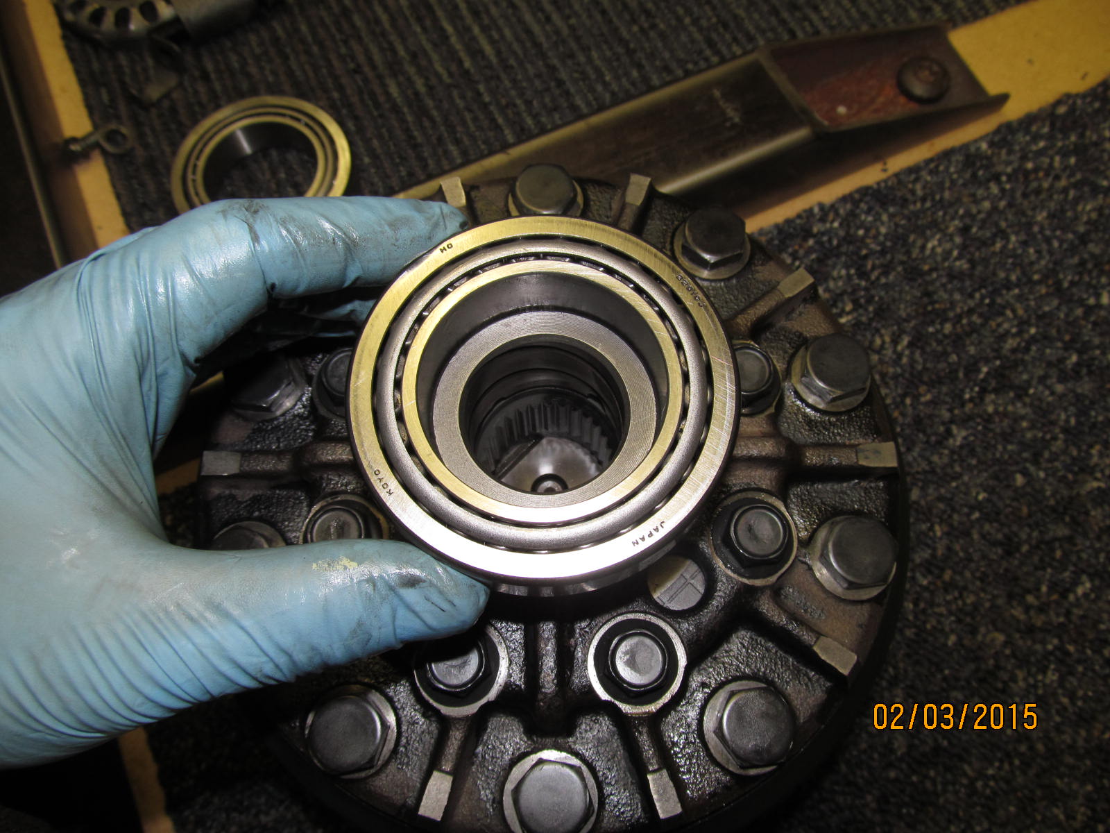
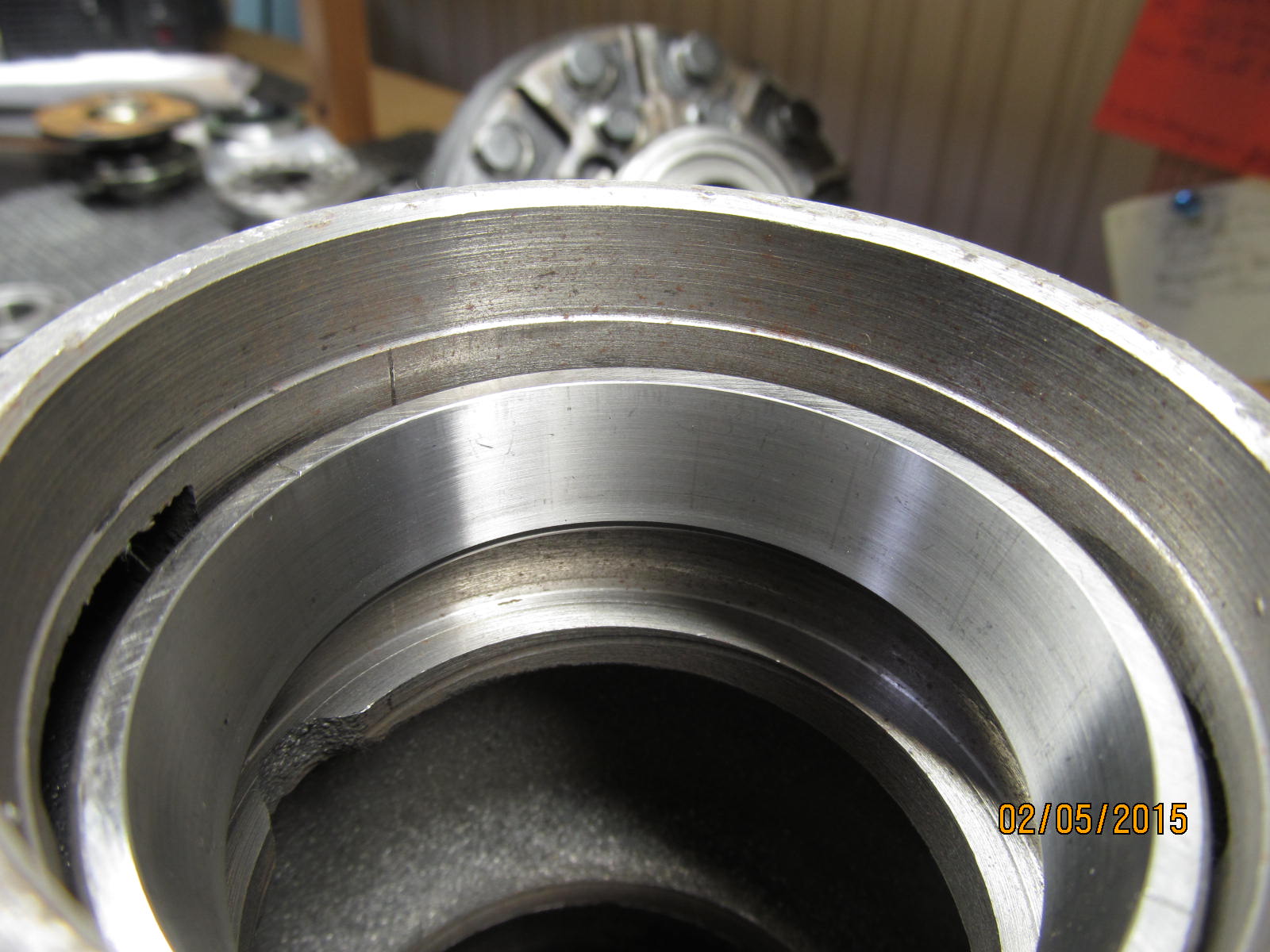
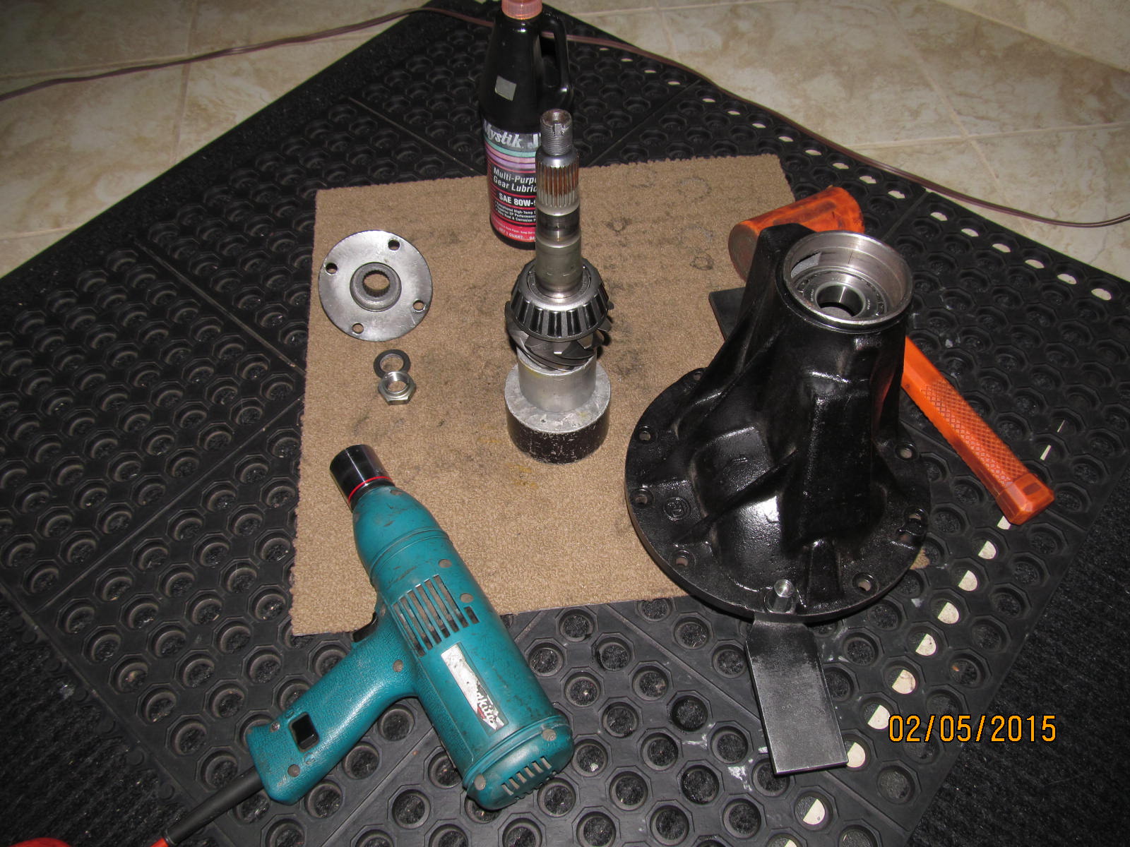
Conversion bearings will allow us to fit this inner case with larger 50mm journals into a 4 cyl outer carrier that
normally sees 45 mm journals.
|
|
|
|
|
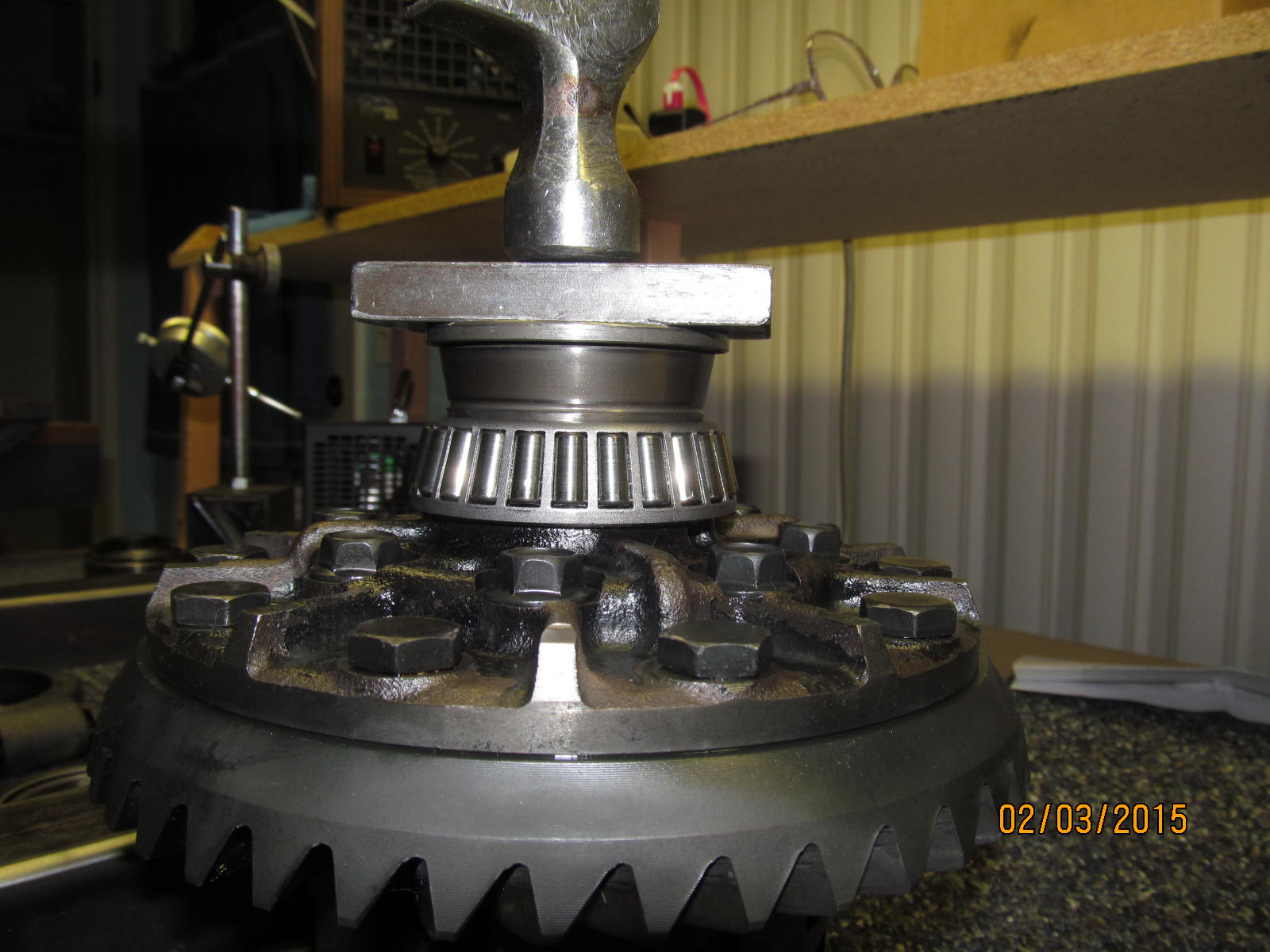
Using old bearing parts, the new bearing is pounded into place.....and it did POUND on. It was a nice, tight fit.
|
|
|
|
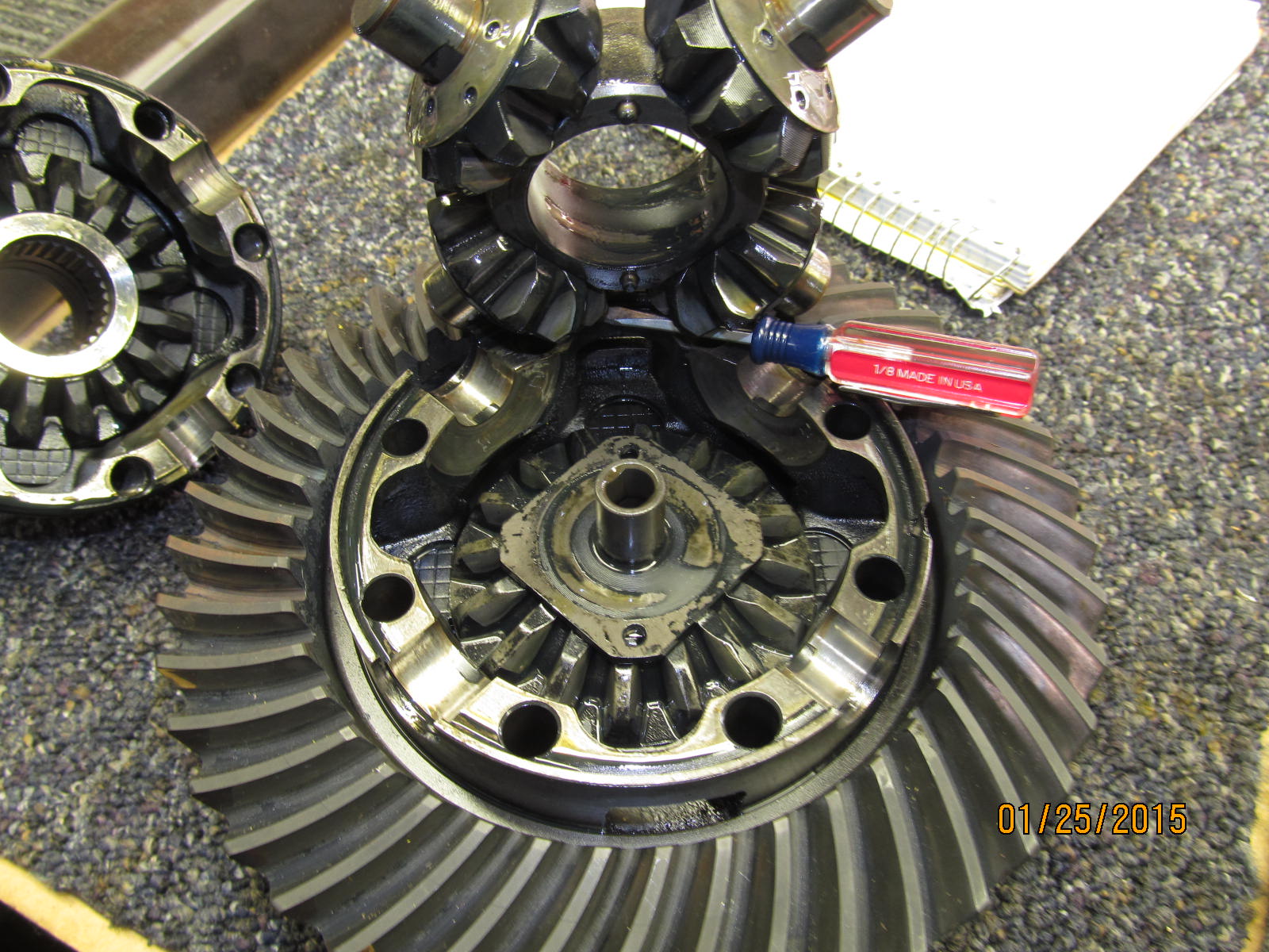
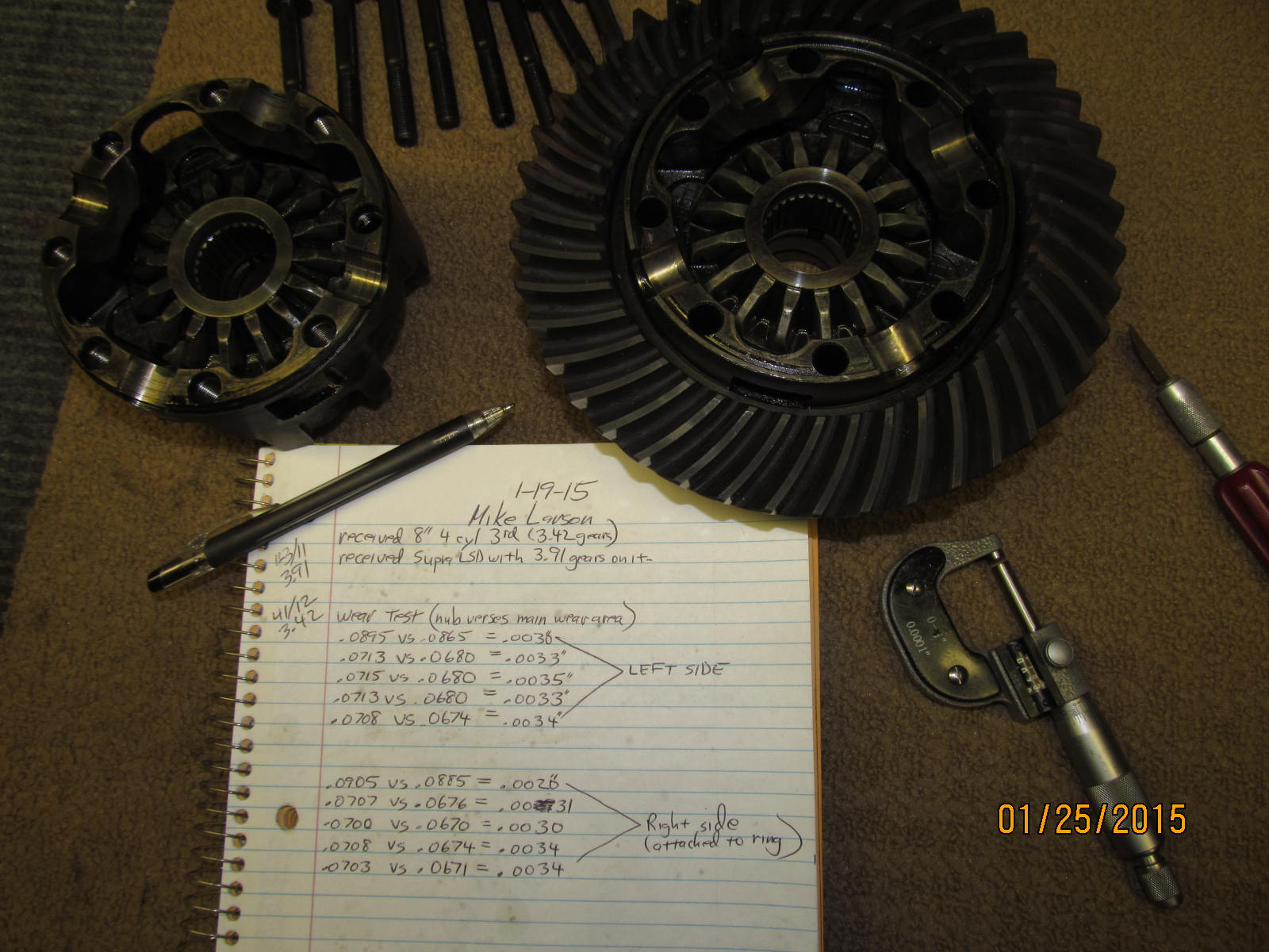
Mike's 3rd had 343 gears in it......the pinion has 12 teeth so it takes up a lot of space. The bore hole is moved
farther to the outside so this 3rd on the left is only suitable for low numeric gears....Toyota has a carrier
split similar to what the Jeep guys experience when the switch from 307 gears up to 411 or 456. The 3rd on
the right is a common 4 cyl 3rd and will accept anything from 373 to 571 gears including the used 390
gears that we are installing here..
|
|
|
|
|
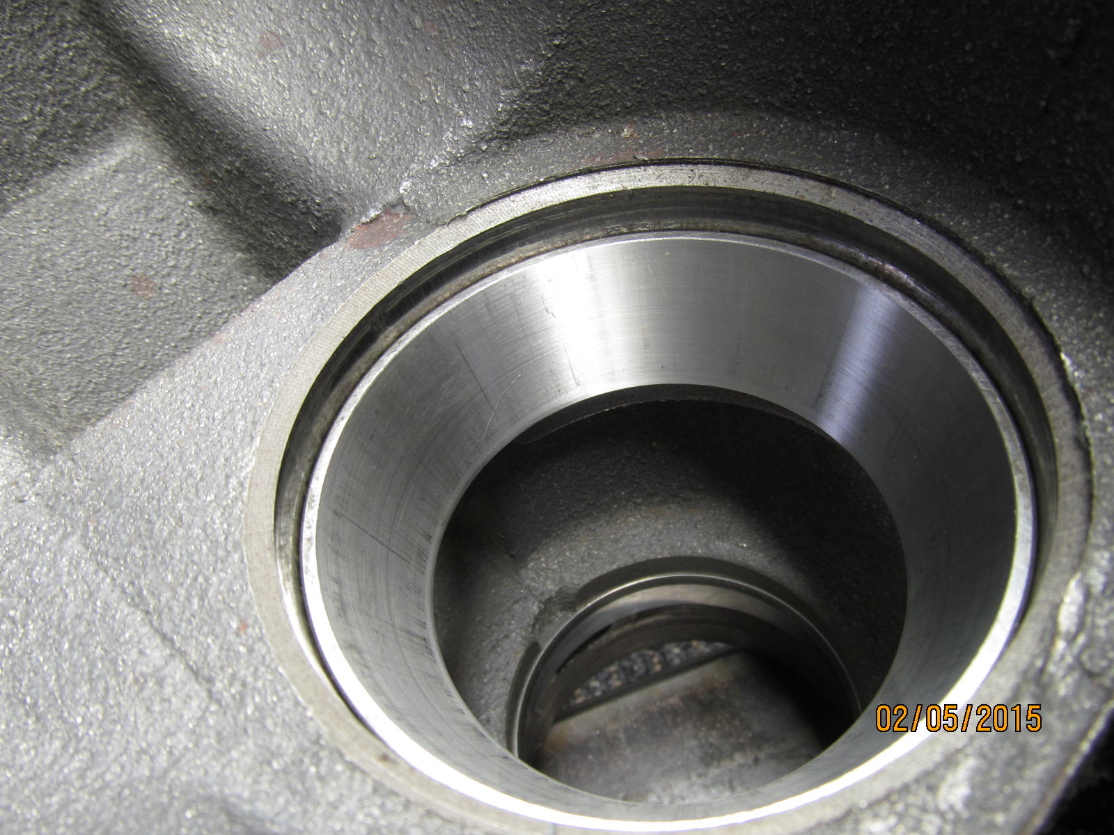
A new outer pinion race is to be tapped in place in the new 3rd.
|
|
|
|
|
Old bearing pieces make that operation easy with no damage to the race.
|
|
|
|
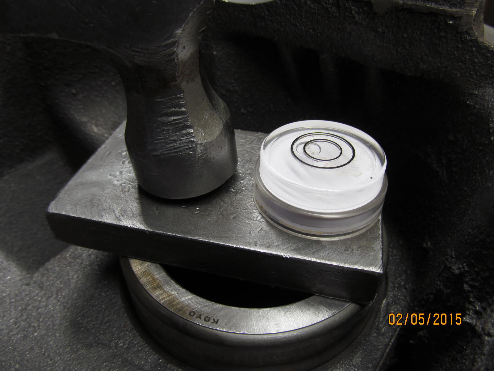
Normally, I press the largethe inner race in place but hammer worked here. The new race cannot even be seen...
it's already tapped in using an old race, a thick steel plate, and a bubble. The bubble makes it so much easier
to seat the new race down without it getting jammed up in the bore. Using the bubble, it can be kept level
and the race will go down smoothly.
|
|
|
|
|
.................
|
|
|
|
|
Using a .077" pinion shim for the first....
|
|
|
|
|
Assemble the pinion into the 3rd.
|
|
|
|
The electric impact is not "brutal" in the way it goes about tightening up the pinion nut and it was easy to
get a 10 or 20 inch/pound resistance feel. No actual torque wrench measurement is really needed at this
stage. That will be saved for the final assembly.
|
|
|
|
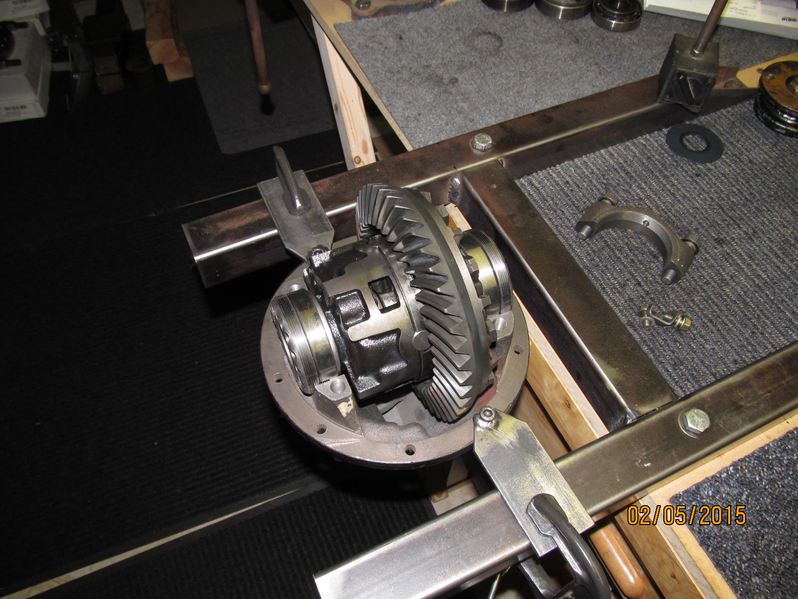
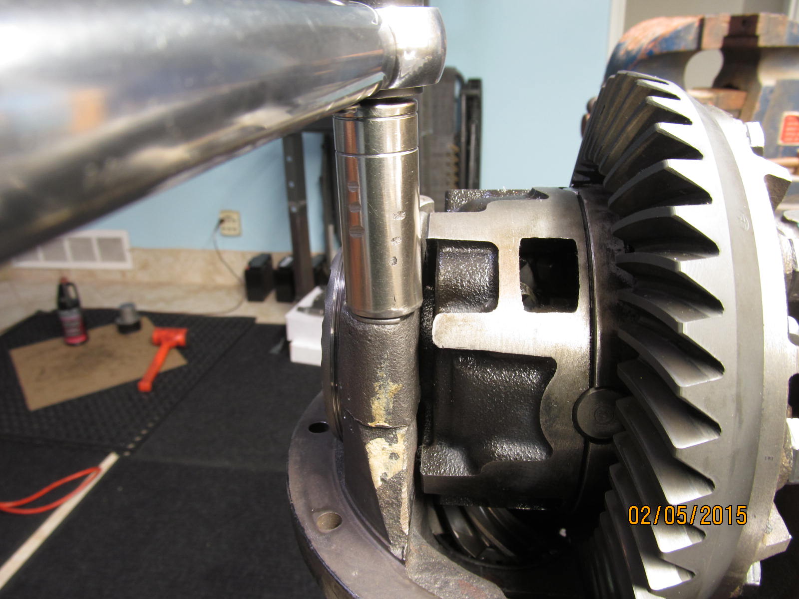
Ring gear assembly is in and the wheel adjusters are in place. In the past, on the right side, I have used a thick
washer plate of about .100" to prevent the wheel from going too deep and bottoming out but that is not
the case here as I discovered. No washer plate will be needed.
|
|
|
|
|
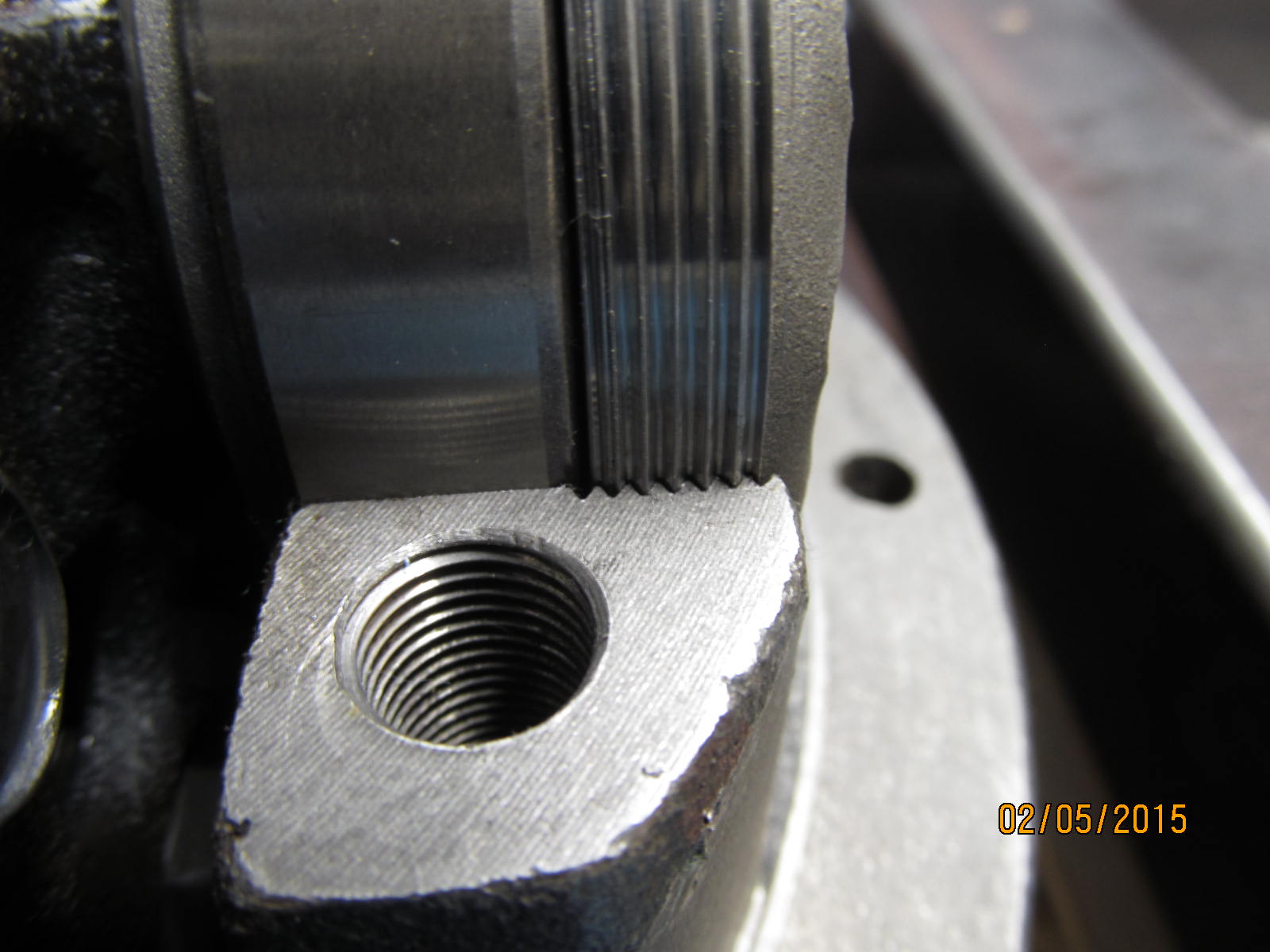
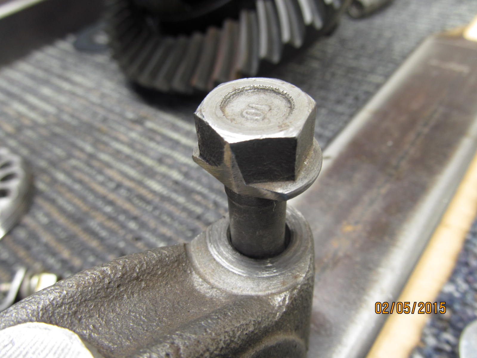
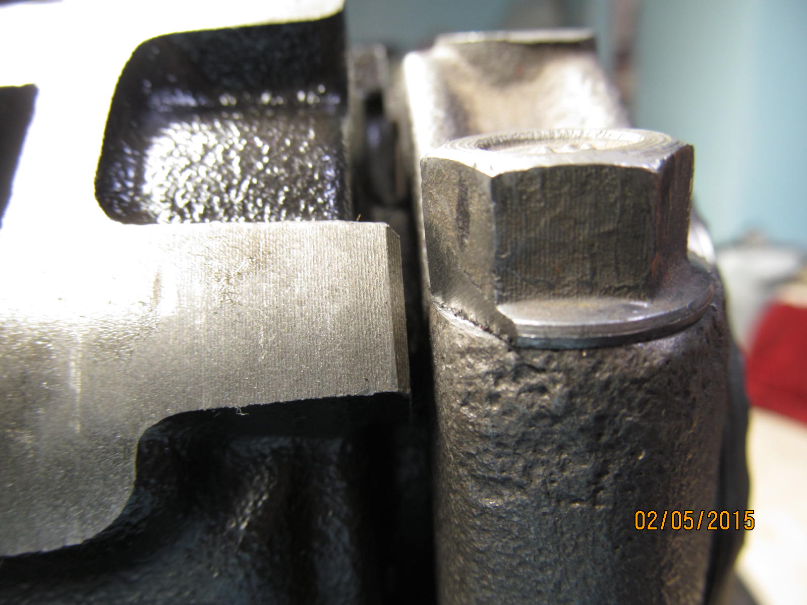
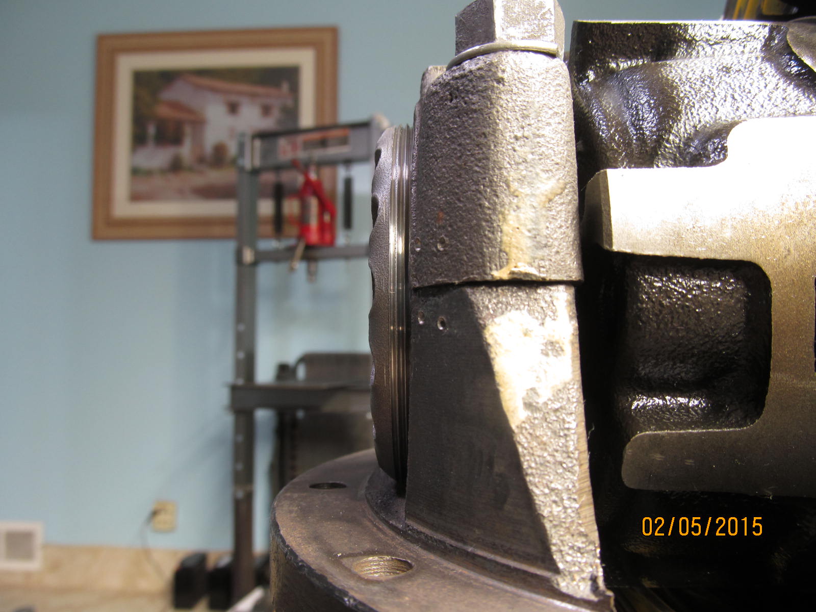
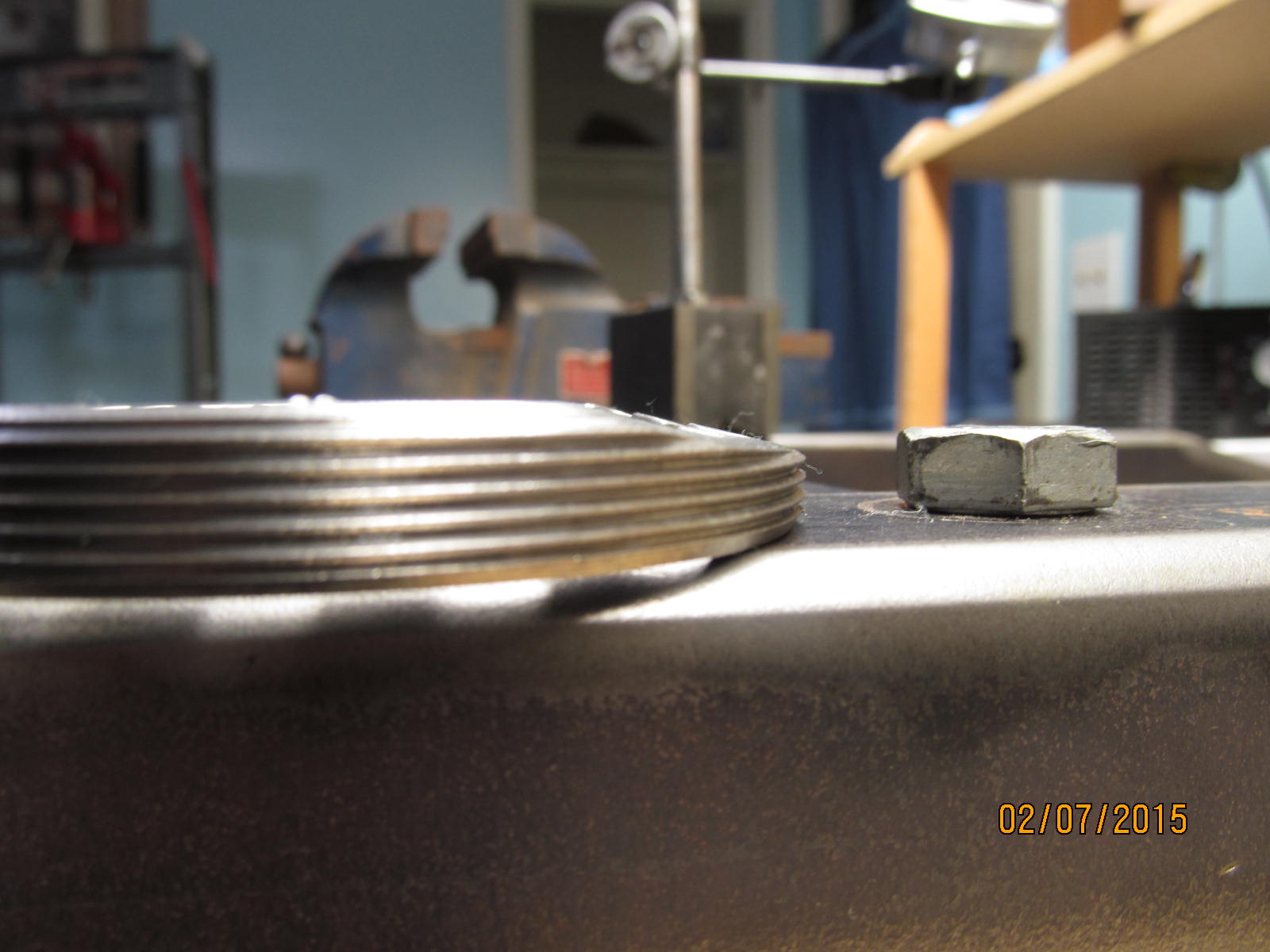
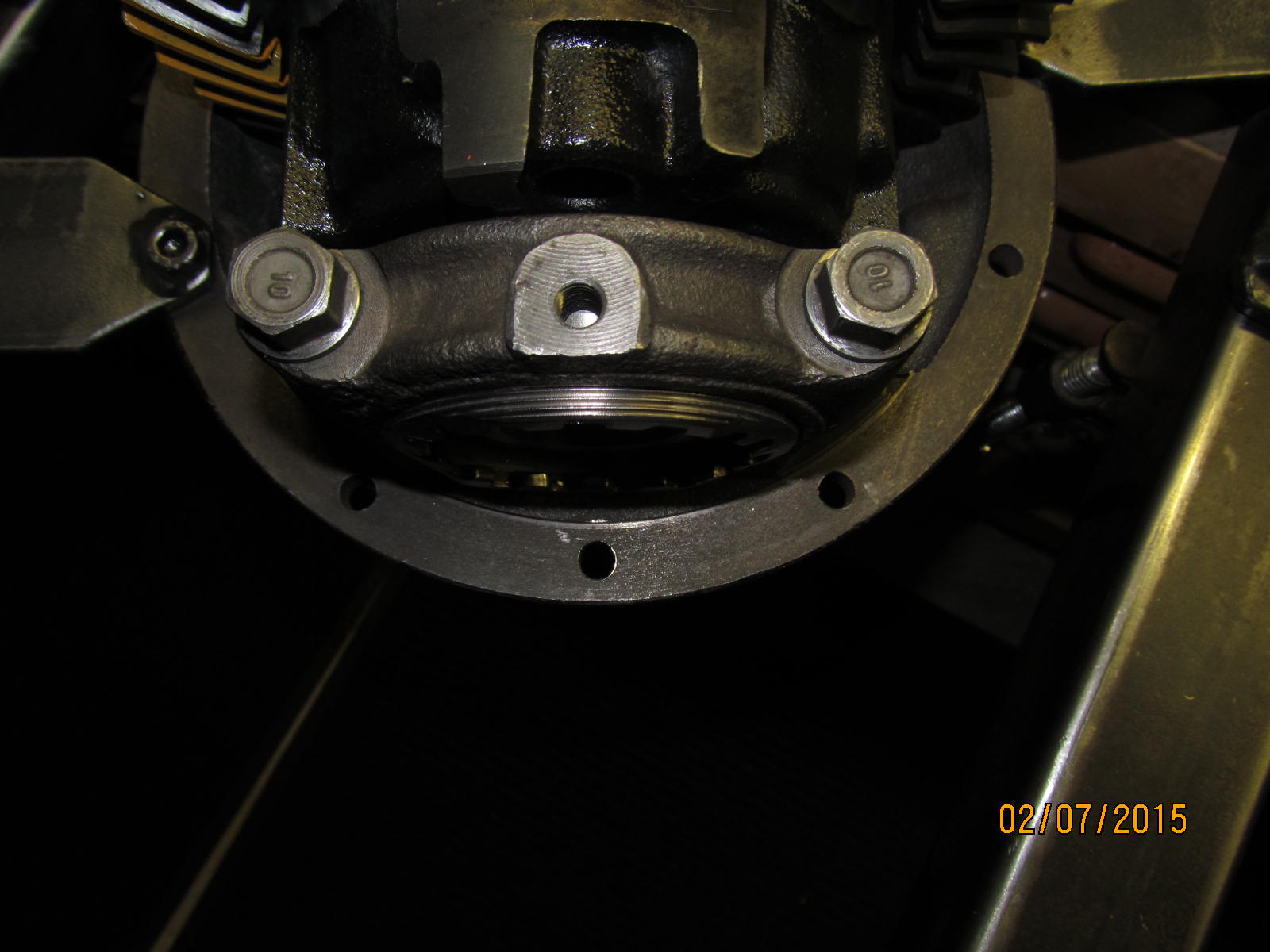
Right side...full thread engagement with some room to allow adjustment.
|
|
|
|
|
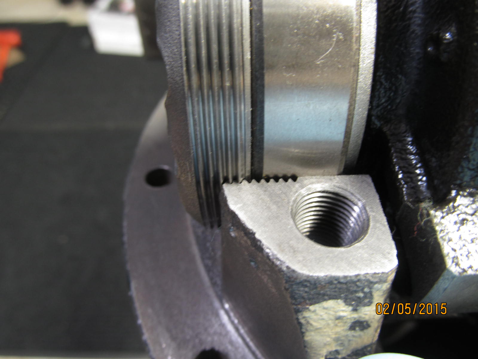
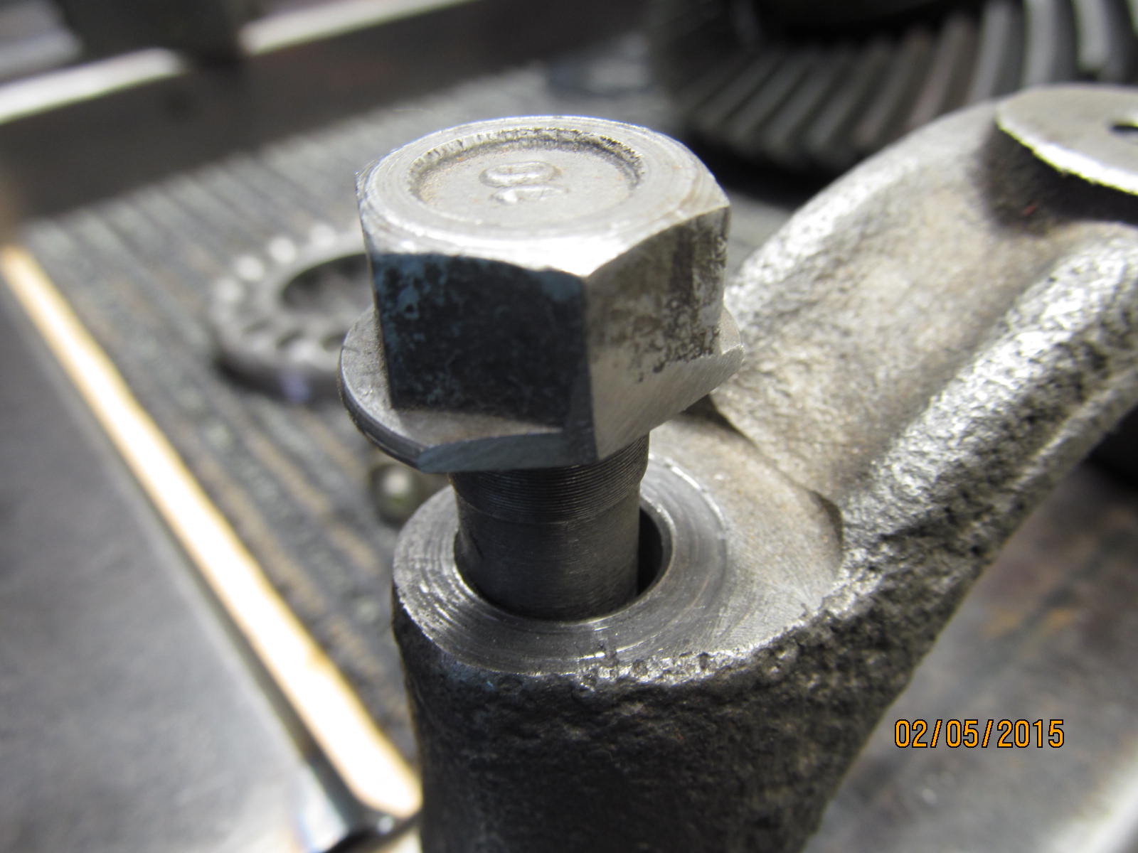
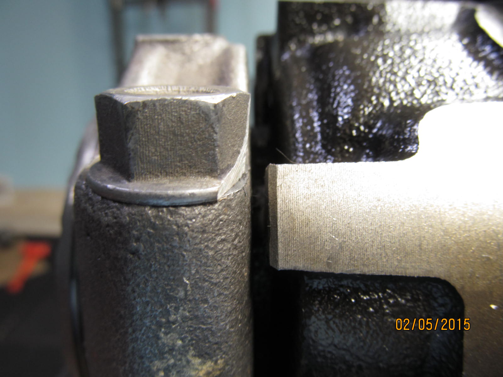
Left side...minimal thread engagement. It's a good thing that this "left side" sees less axial strain than the right.
|
|
|
|
|
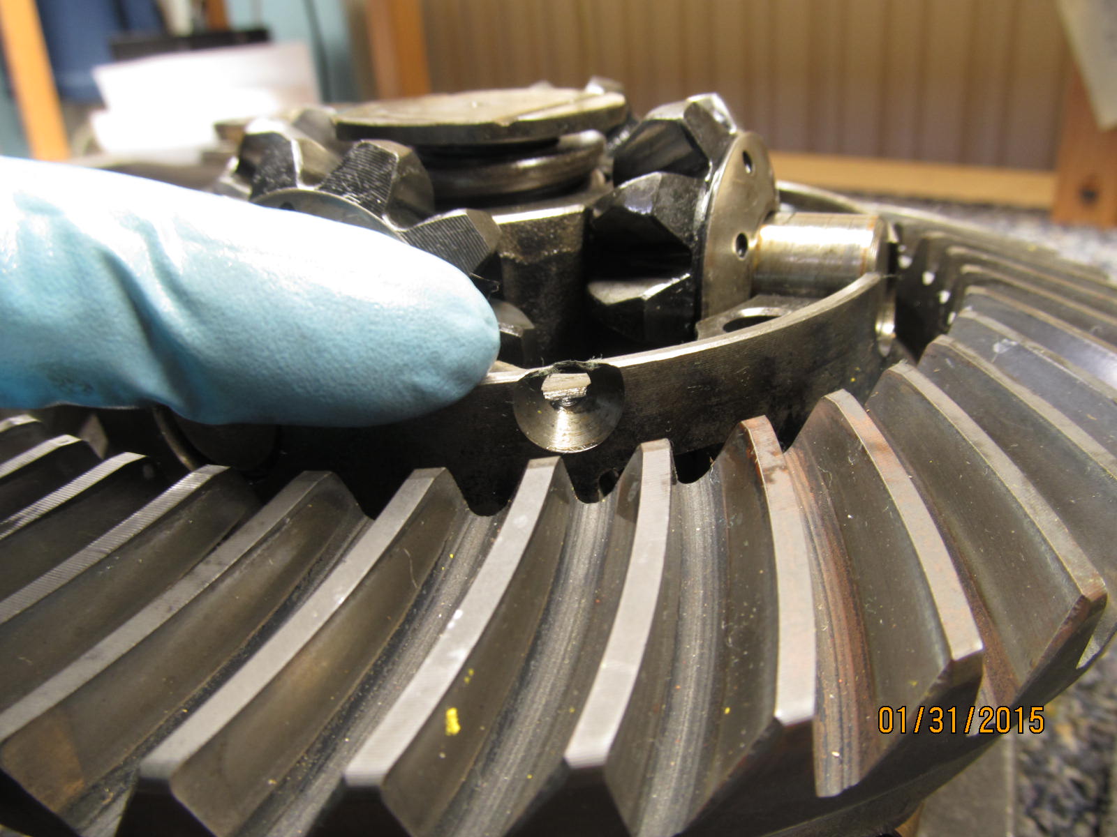
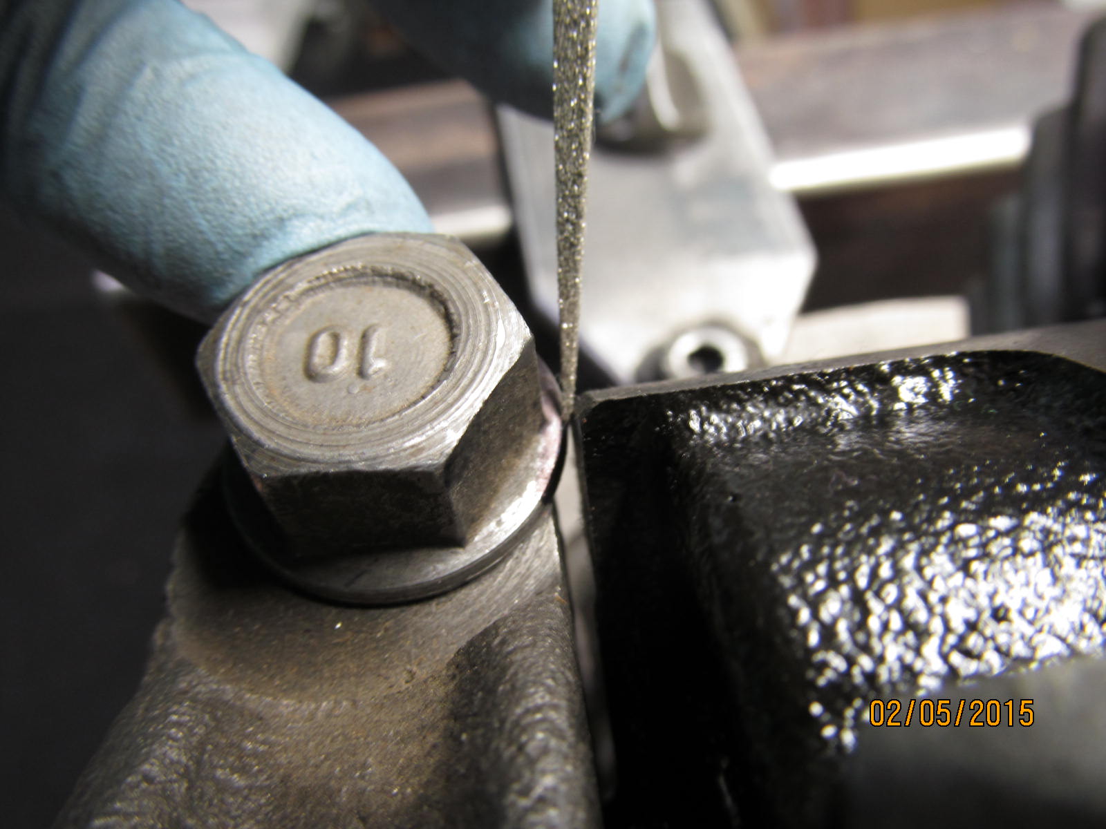
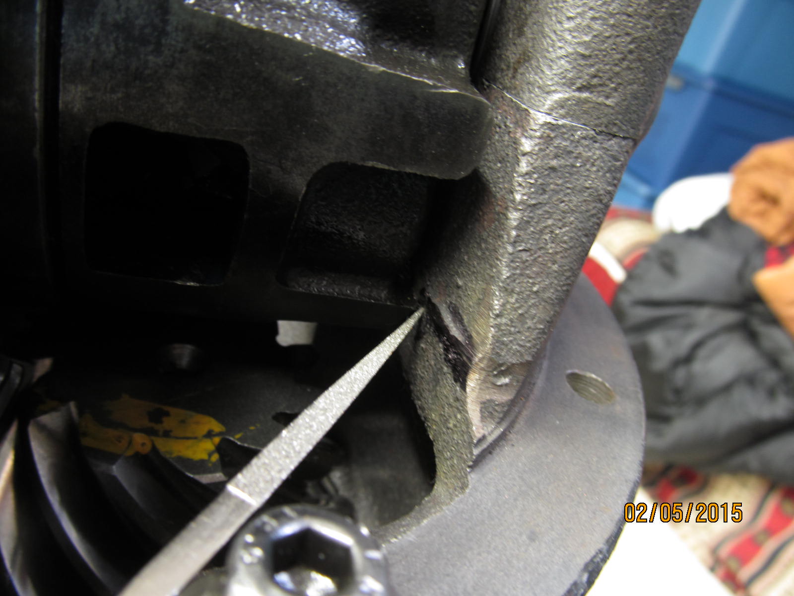
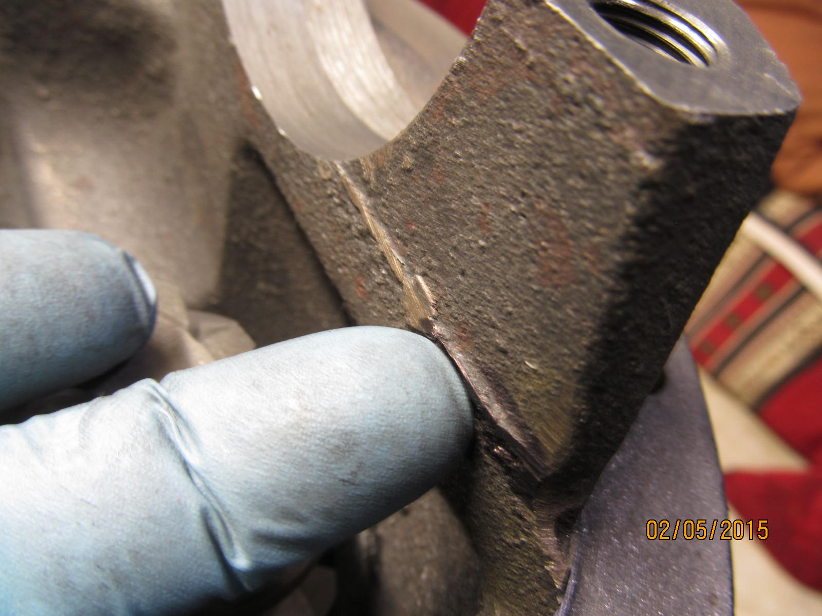
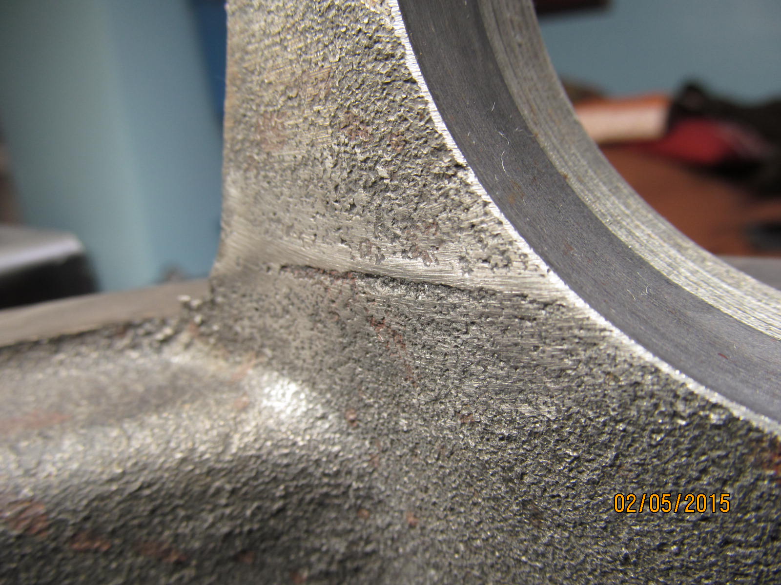
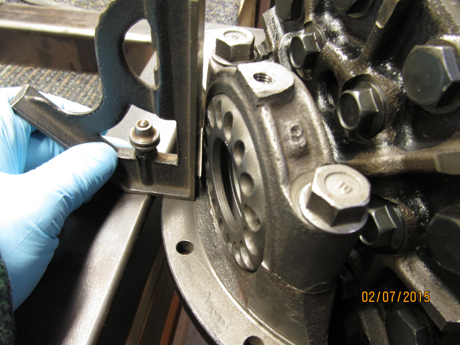
Minor clearancing will have to be done. I'll trim the flanged bolt here as shown with the file tip.
|
|
|
|
|
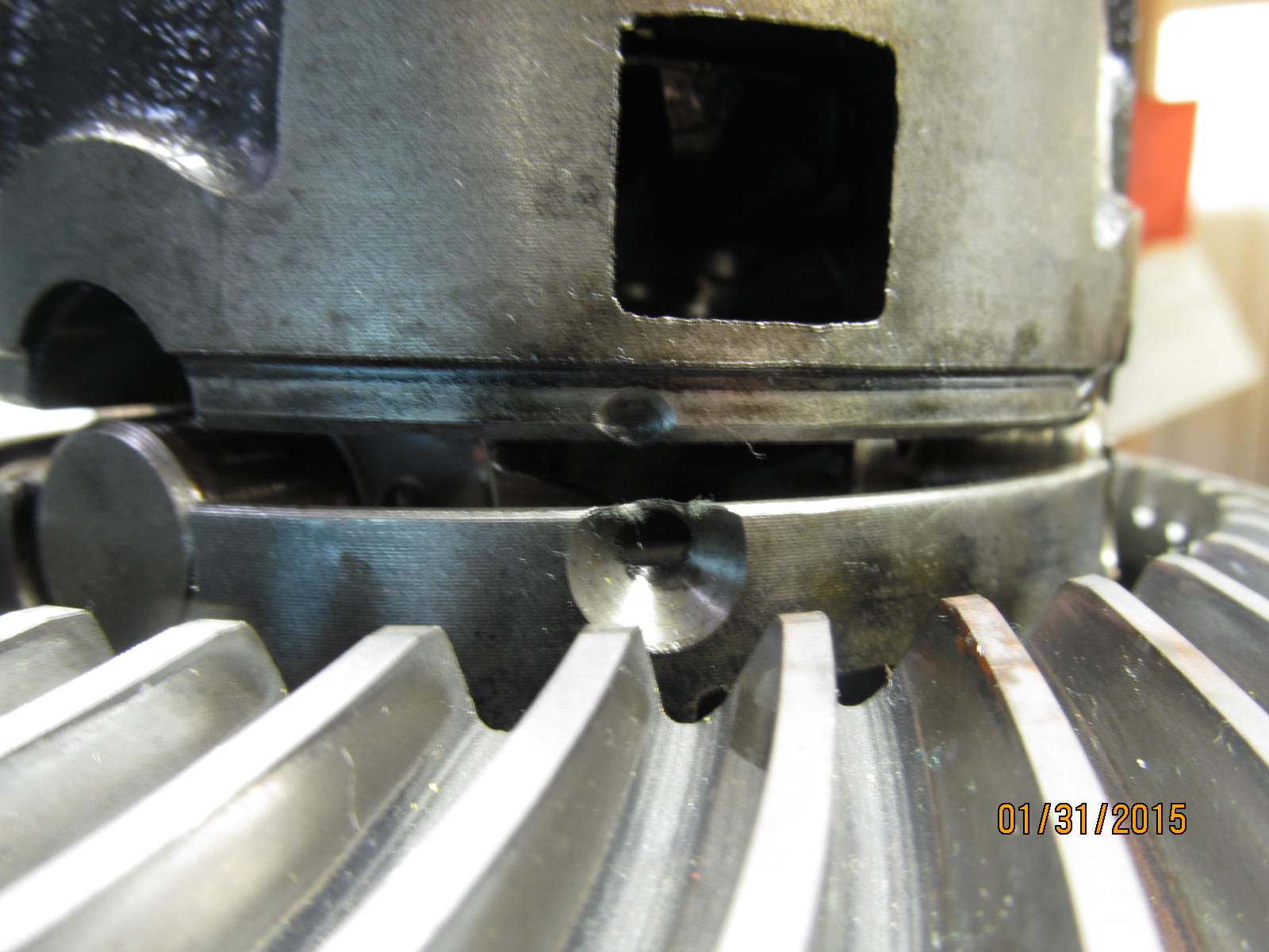
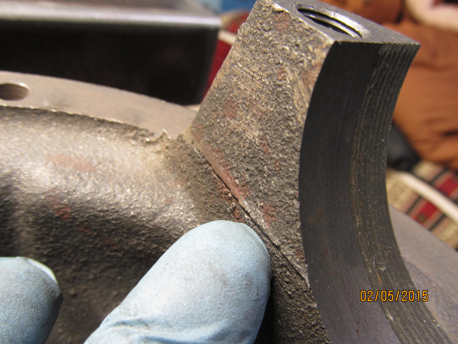
It's contacting the overcasted material as shown above. A flapper wheel will smooth it out beautifully.
|
|
|
|
|
Ring gear assembly is out and now the flapper wheel has easy access here.
|
|
|
|
|
The other side is not as bad.
|
|
|
|
|
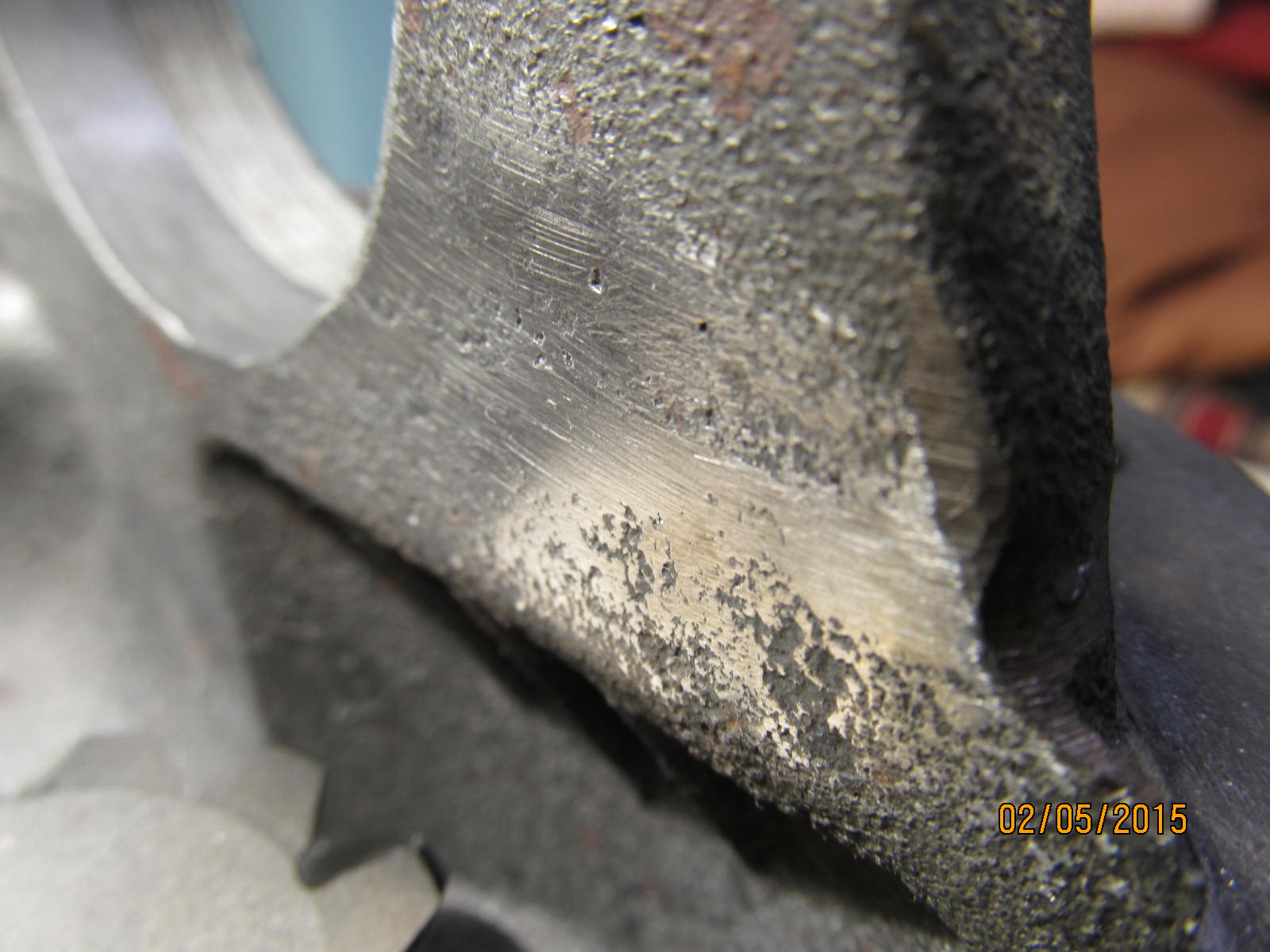
The flapper wheel took care of the bad lip easily enough.
|
|
|
|
|
And the side was smoothed out a little more.
|
|
|
|
|
The bolts were tightened to 75 ft/lb and marked where they needed to be flappered a little.
|
|
|
|
|
.................
|
|
|
|
|
....back to 75 ft/lbs....
|
|
|
|
|
perfect. Lots of clearance now.
|
|
|
|
|
..................
|
|
|
|
|
And the overcasted area is no longer an issue.
|
|
|
|
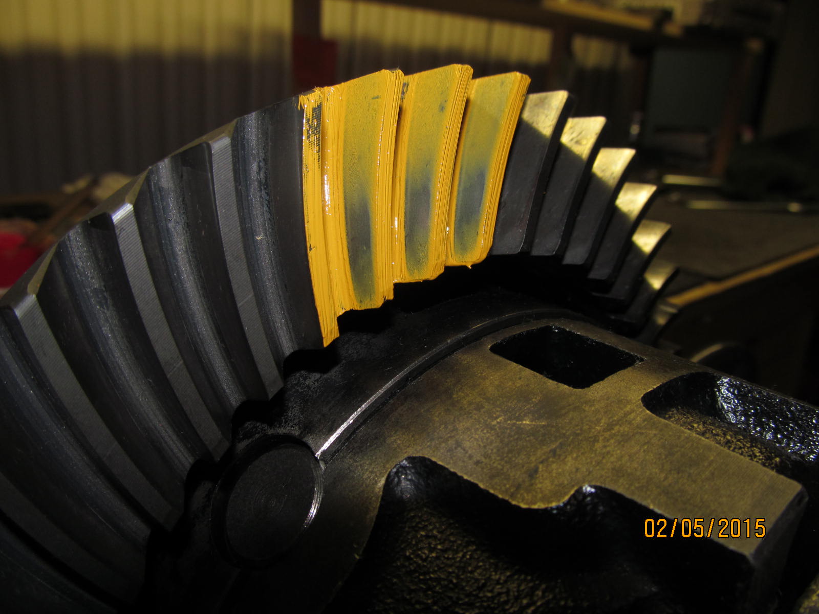
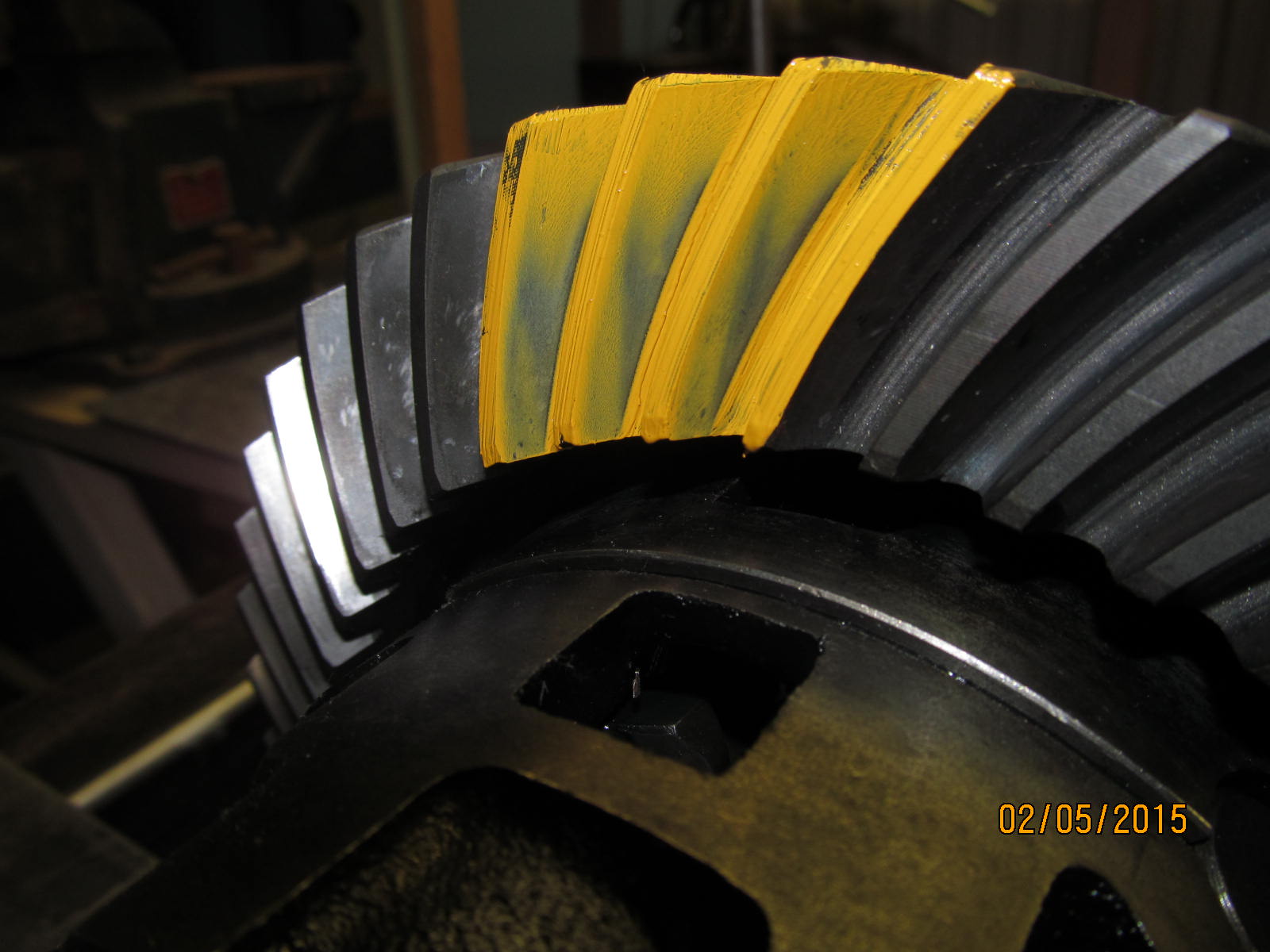
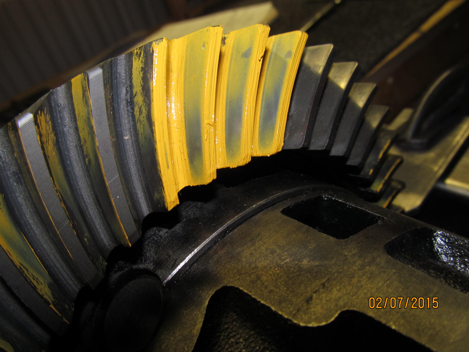
Now that the ring gear can actually turn without interference, the pattern can be checked. This is the drive side.
Looks good.
|
|
|
|
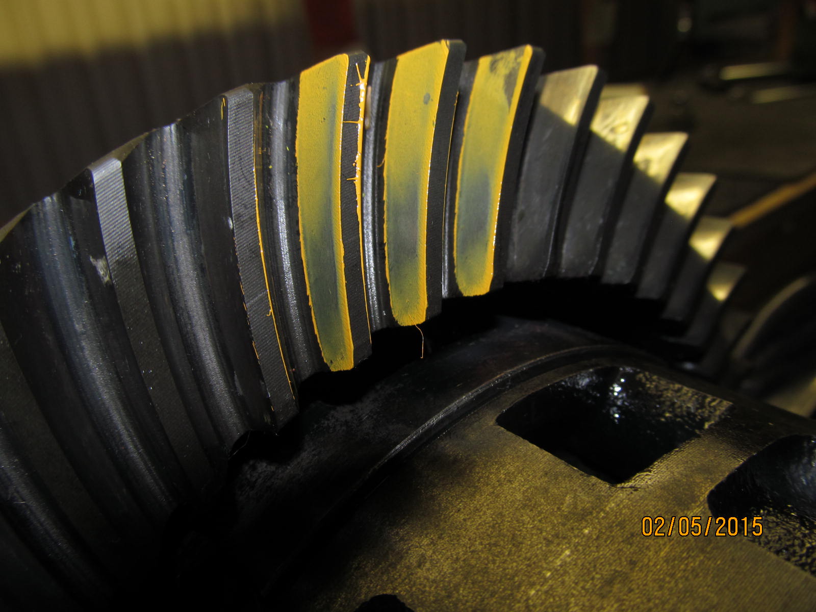
Coast side. Appears deep and harsh contact in the root. These 390 gears are used with many miles on them and
apparently saw loosey goosey bearings in the past and the result is shown here. That will disappear with
time as it re-establishes the original wear pattern.
|
|
|
|
|
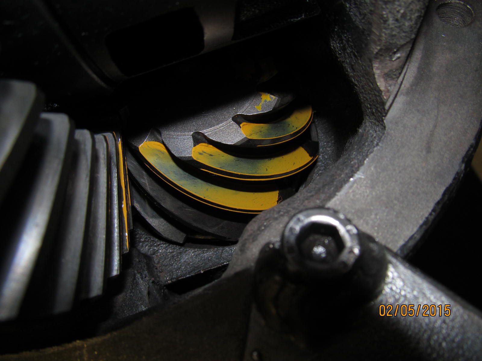
Drive side on the pinion tooth. Looks good.
|
|
|
|
|
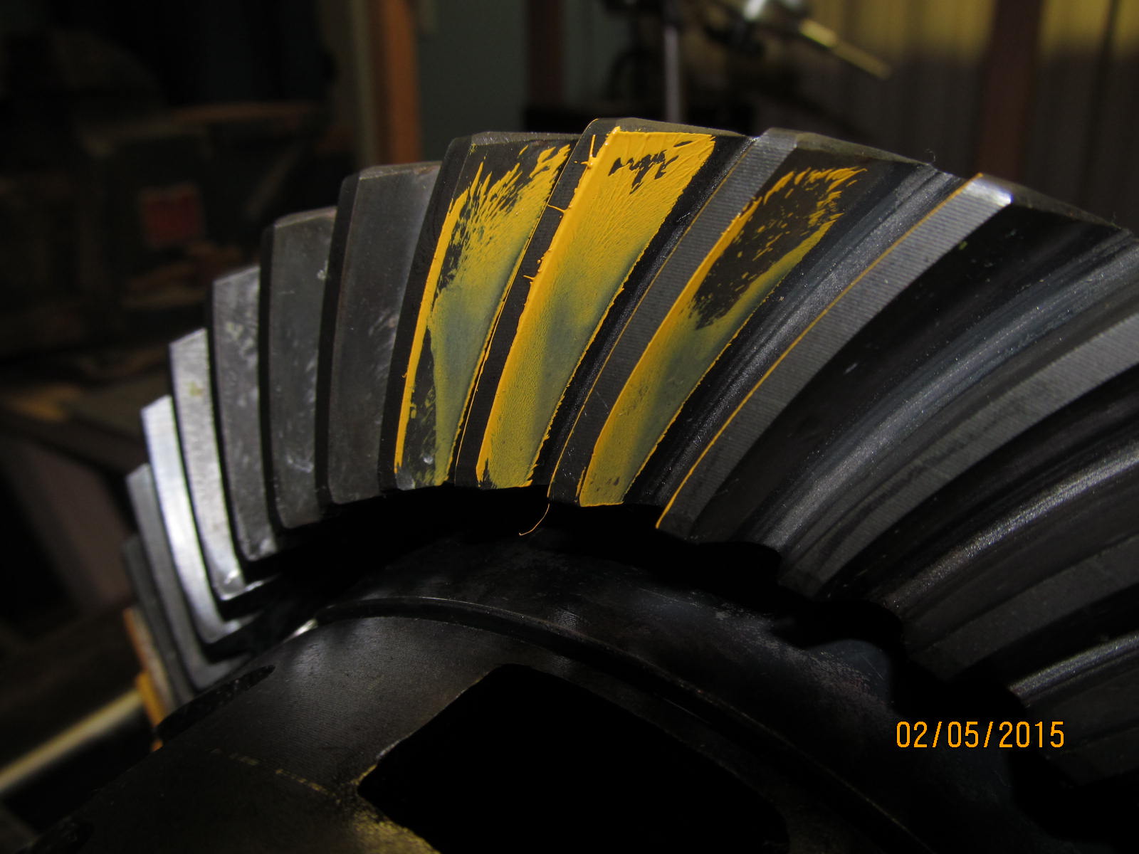
Drive side. Reverse painted.
|
|
|
|
|
Coast ....reverse painted.
|
|
|
|
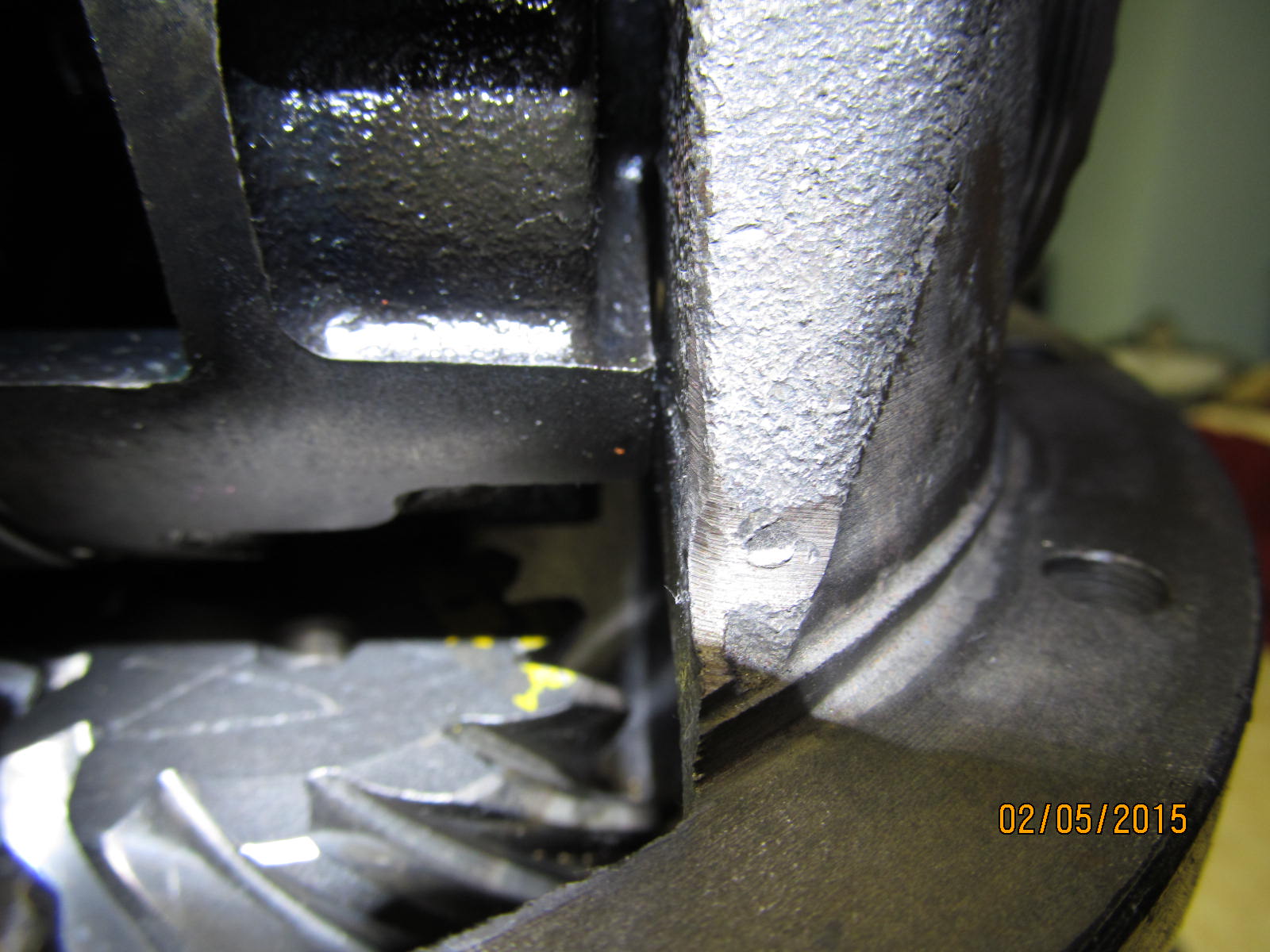
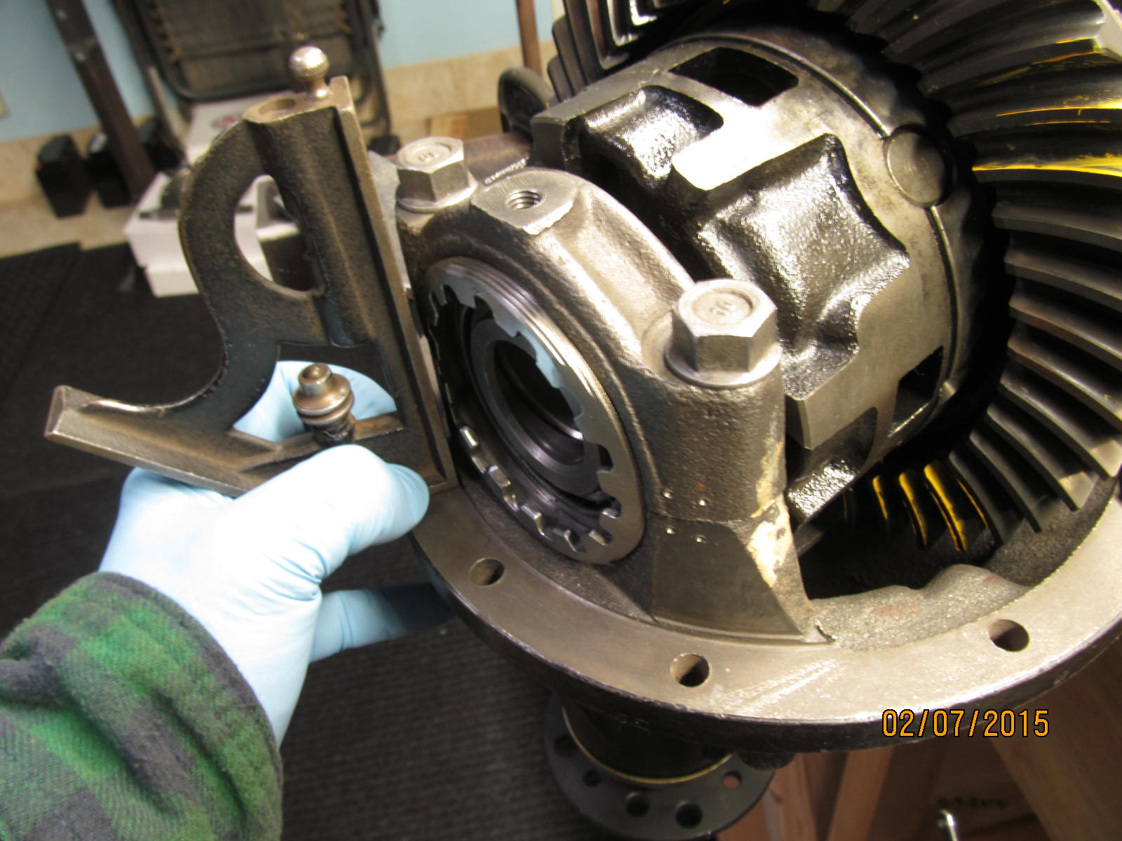
When trying to load the 3rd into the axle housing this wheel adjuster will probably cause some grief requiring the
axle housing opening to be "relieved" where this wheel would normally contact.
|
|
|
|
|
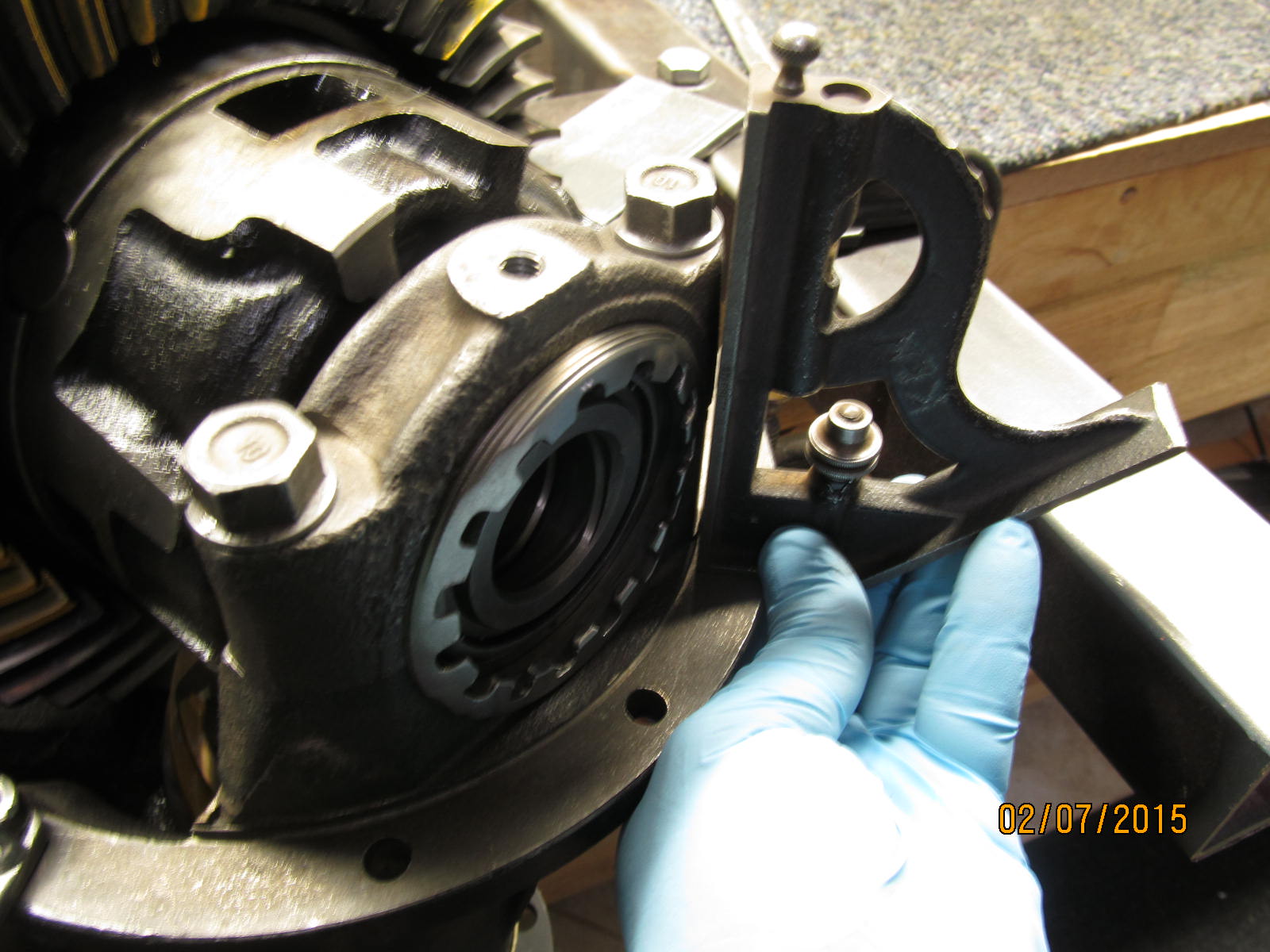
But I think I can save Mike some grinding time by substituting an "ARB wheel" and grinding the 2 corners down.
|
|
|
|
|
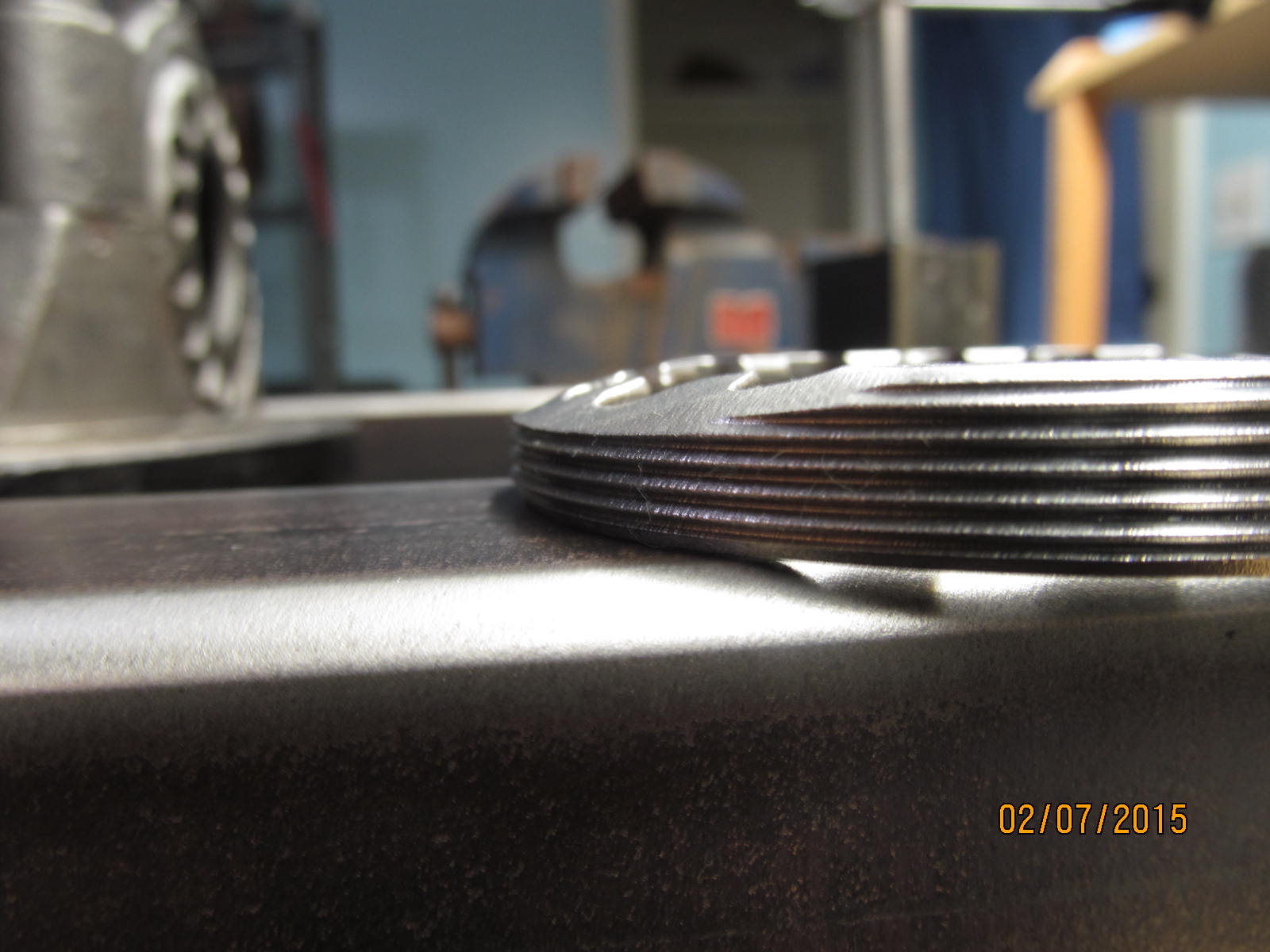
THe ARB wheel is much thinner to start with.
|
|
|
|
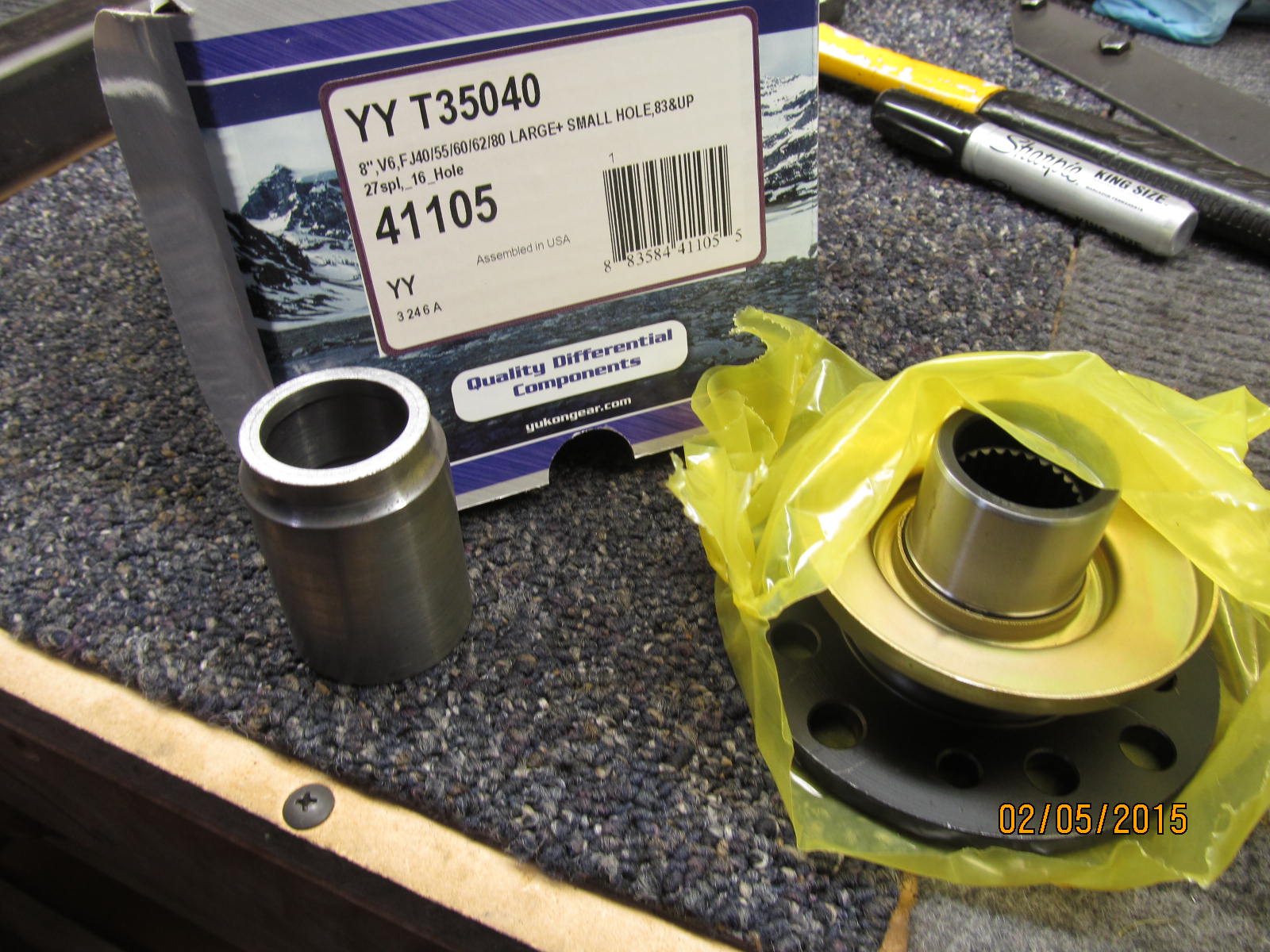
But before that can be done, the pinion end of things has to be final assembled.....solid collar and
new triple drilled flange.
|
|
|
|
|
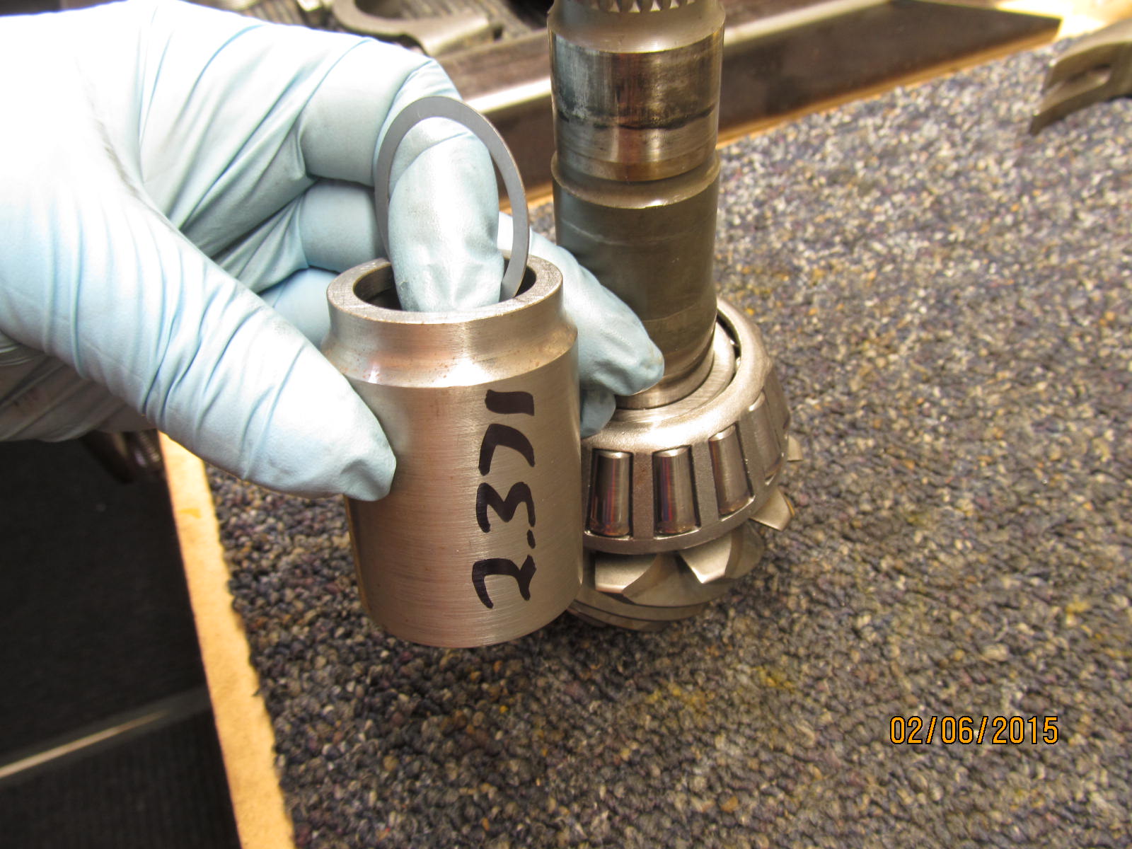
I skipped a few steps but found that the 2.371" collar and a .019" shim did the trick.
|
|
|
|
|
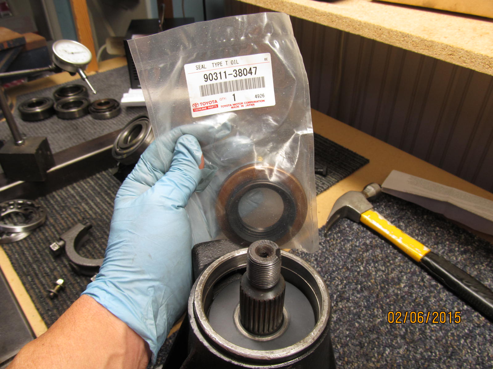
A new oem 90311-38047 seal will be used.
|
|
|
|
|
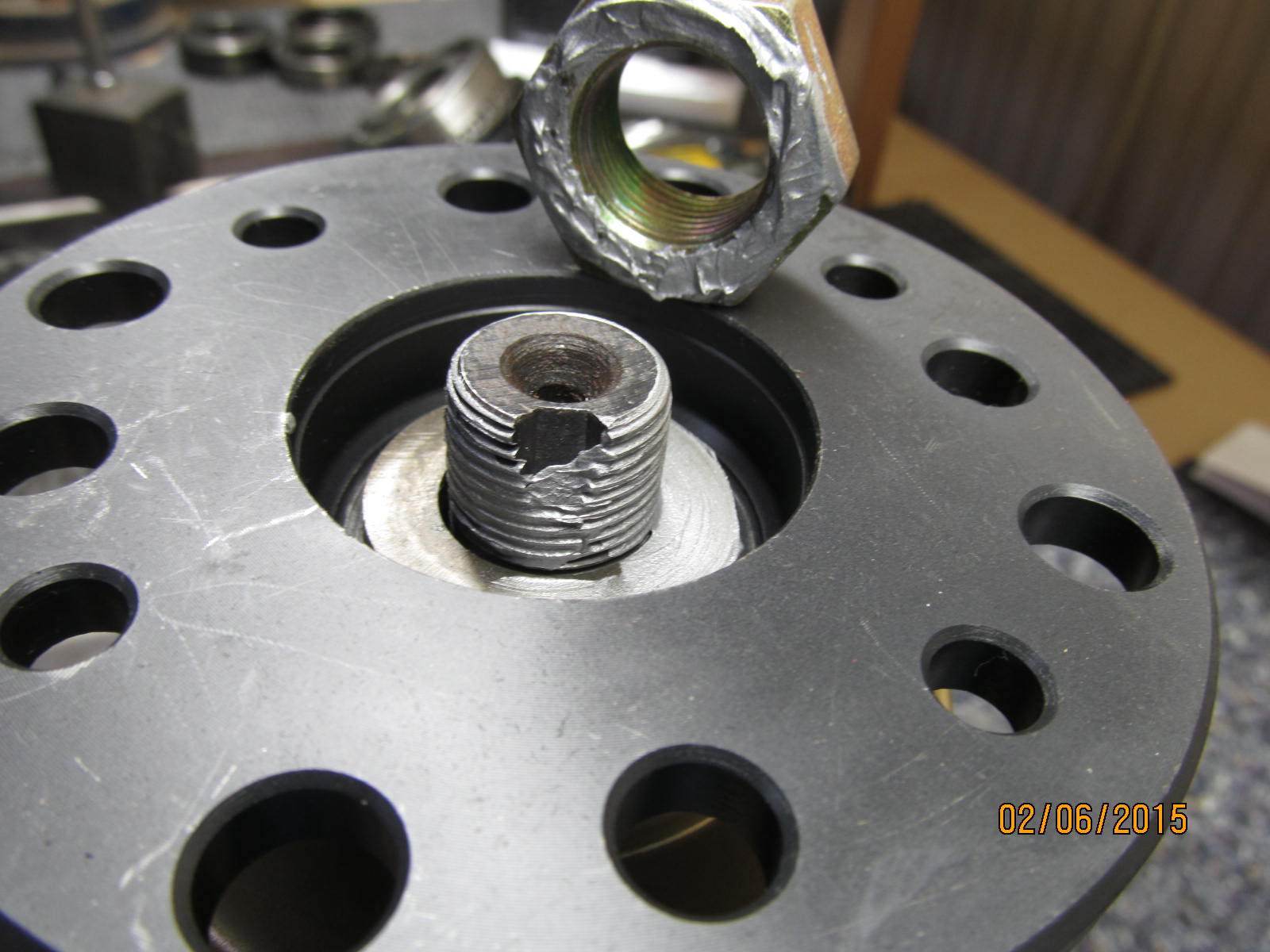
Lots of anti-seize.
|
|
|
|
|
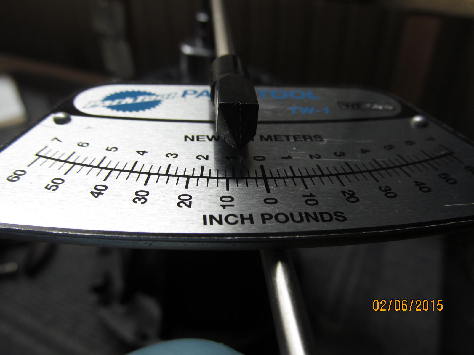
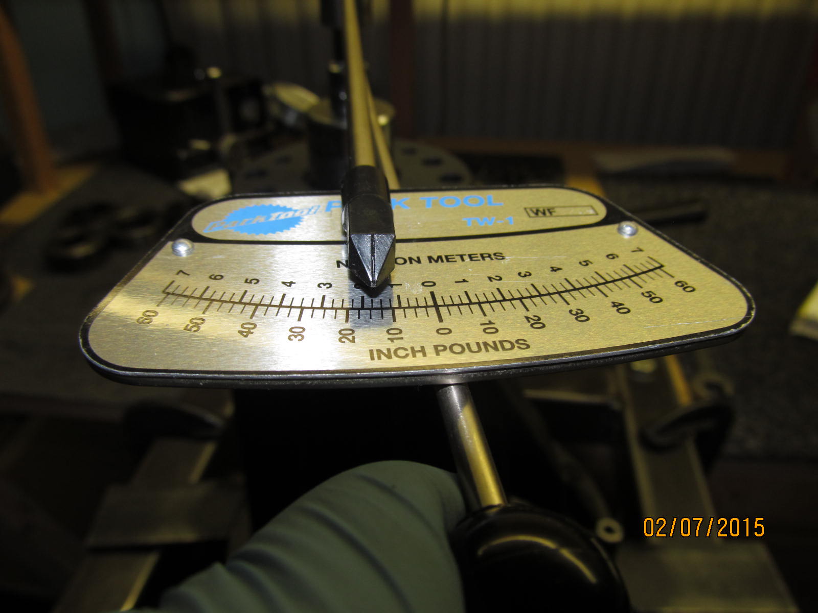
Final PPL measured at 8 in/lb start torque.
|
|
|
|
|
DING and this end is done.
|
|
|
|
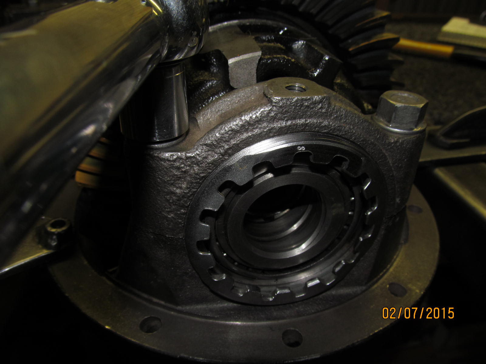
Before the ARB wheel could be clearanced, everything had to be set....backlash....and carrier bearing pre-load.
With the wheel in the final known position, I could mark it and flapper wheel it to make the sharp edges go
away....and here's the result.
|
|
|
|
|
...the other side. Now to re-assemble the ring gear end....
|
|
|
|
|
....As seen here, the wheel on the other side is a no-issue......
|
|
|
|
|
...and the problem wheel looks A-OK. Looks like it will clear like a gem.
|
|
|
|
|
Mike will not have to do any grinding I can see.
|
|
|
|
|
................
|
|
|
|
Bearing cap bolts are final checked for 75 ft/lb and all is good. Not visible in the pic but the flange lips on
the bolts is in perfect alignment to never hit the LSD case.
|
|
|
|
|
...................
|
|
|
|
|
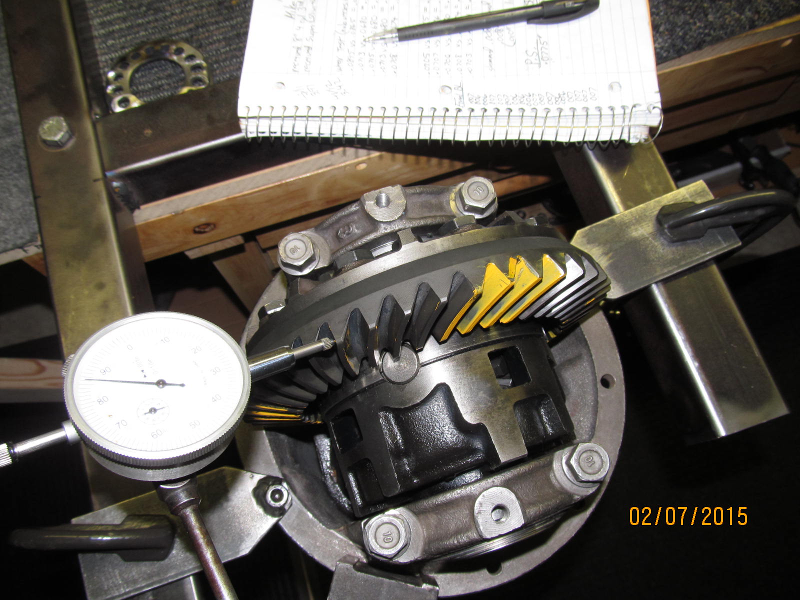
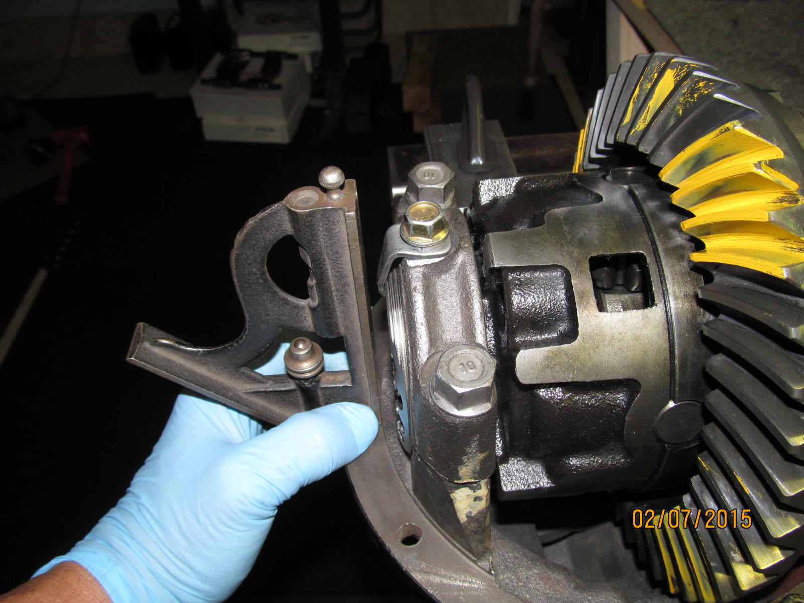
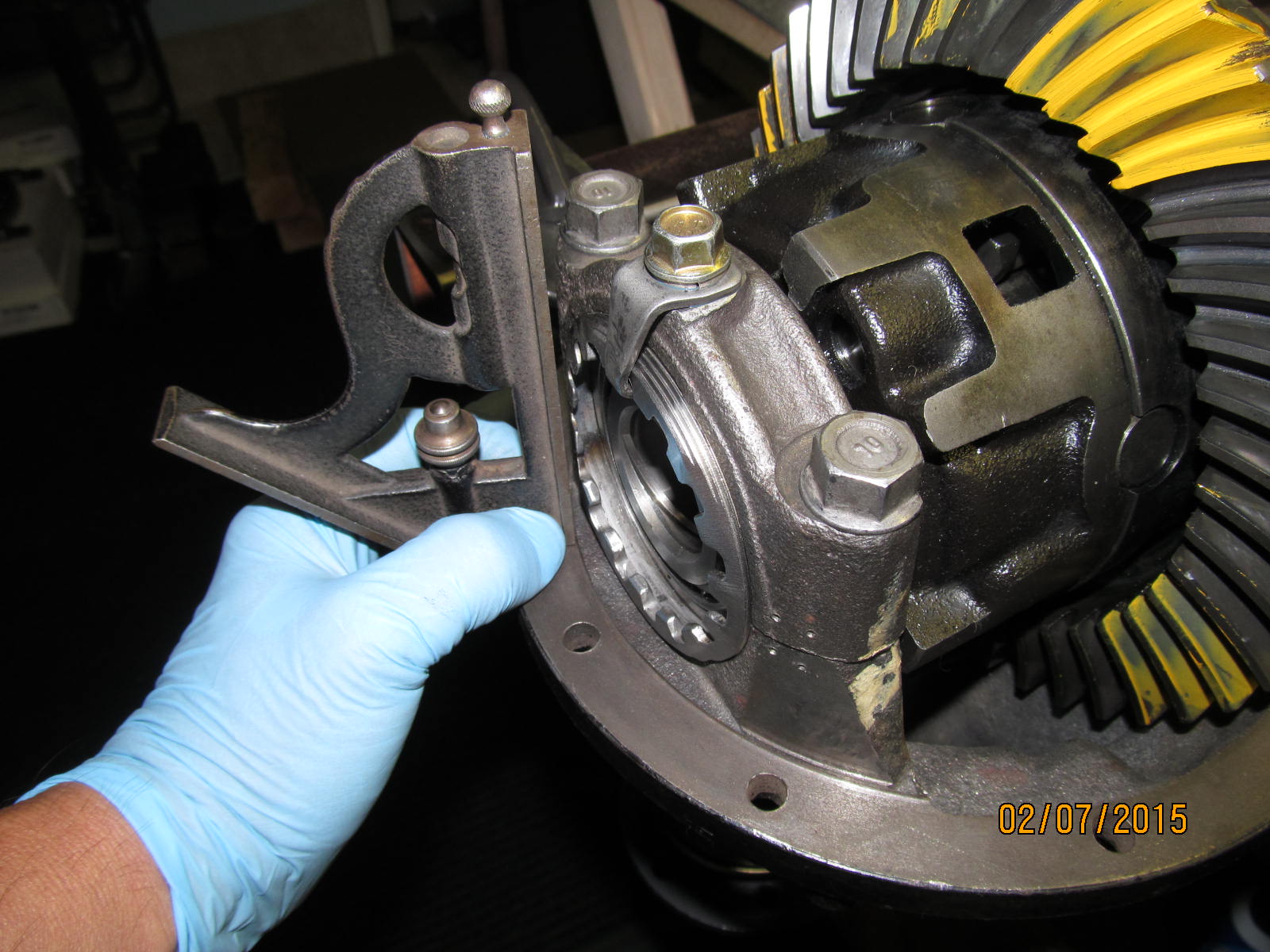
Ring gear has the proper amount of resistance to turning....but the best way to make sure is to actually measure it.
|
|
|
|
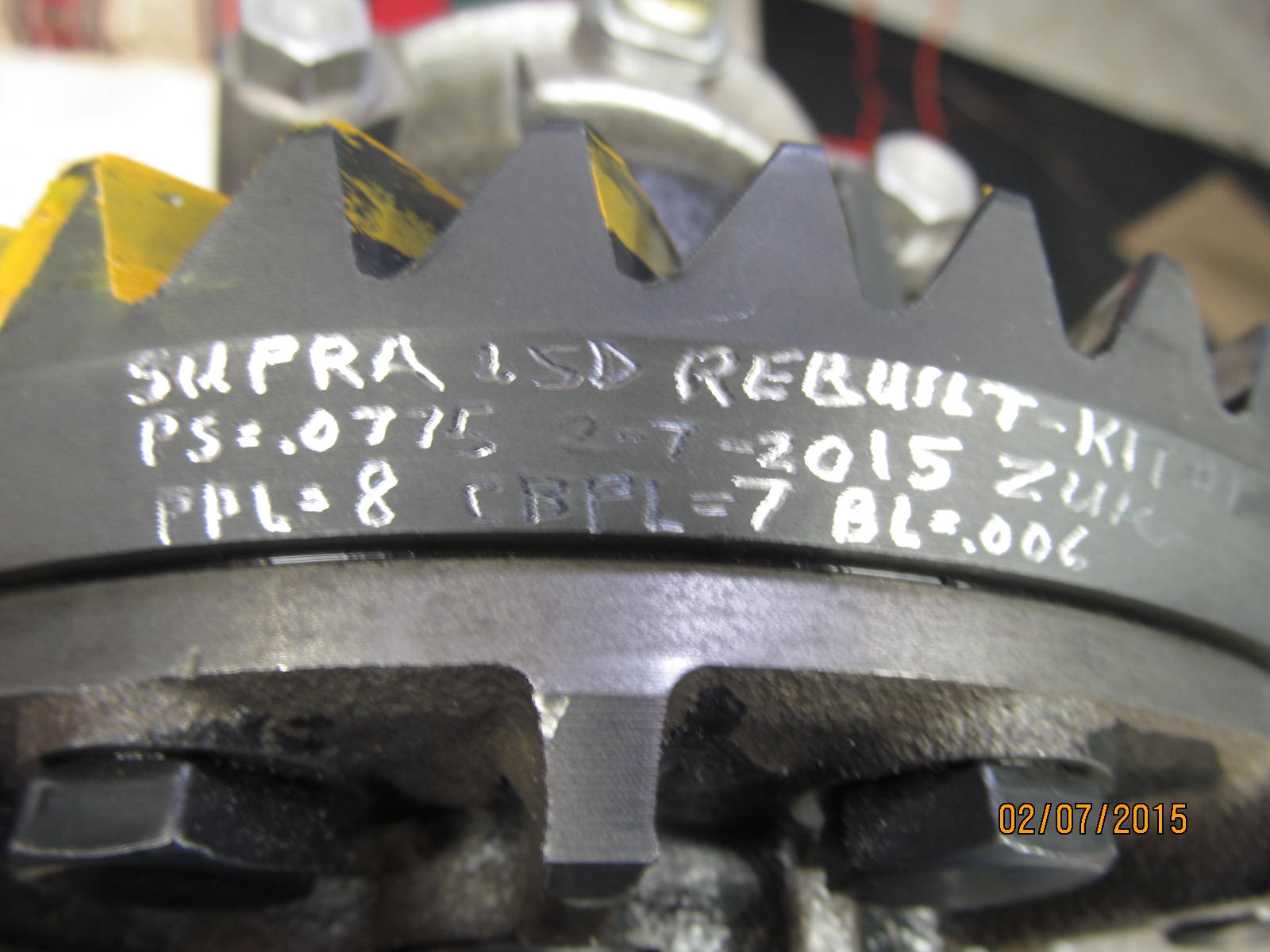
The total preload to turn BOTH the pinion bearings and carrier bearings is 15 in/lb. The measured pinion preload
alone is 8 in/lb so, doing the math, 15-8= 7 in/lb CBPL.
|
|
|
|
Backlash was measure in 18 places around the ring (it's in the notes at the bottom).....minimum backlash measured
right at .006" and the max measured at .007"...very unusual for only a .001" variance.
|
|
|
|
|
Blue locktite and 10 ft/lb.
|
|
|
|
|
|
One last clearance check.
|
|
|
|
|
.............
|
|
|
|
|
|
One final pattern check....DRIVE.
|
|
|
|
|
COAST.
|
|
|
|
|
|
Measured specs are dremeled on the ring gear.
|
|
|
|
|
Now to box it up in the tote and back to Mike. :)
|
|
|

|